Creating Kitchen layout, Hatching of Architectural elements and sectional view of an Industrial Building in AutoCad
To Create Kitchen layout, Hatching of Architectural elements and sectional view of an Industrial Building in AutoCad
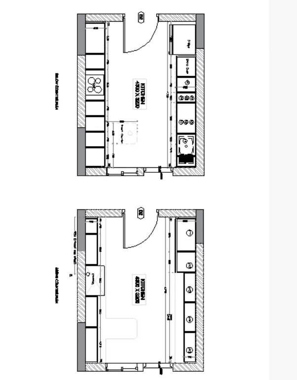
1. Aim : To Create the layouts of the Kitchen and provide hatches pattern as shown.
Commands used:
- LINE
- Offset
- Fillet
- Extend
- Trim
- DIMLINEAR
- Hatch
- DIMTEXT
- Copy
- Layer
- Block
Procedure:
BELOW COUNTER PLAN:
Step 1 :
- Create a new AutoCAD file with imperial settings.
- Command D - units type as "Decimal" (dimension - mm) and set the precision also
- Set the limits with command "LIMITS" enter zoom all.
- Command - UNITS to change the unit option as "Decimal" and set the precision
Step 2 :
- Command - line
- Specify the 1st point and draw a line along x axis length as 4230 units
- Command OFFSET
- Select through option and object and specify the offset distance for below counter outer plan
- Select Home - Layer properties and select the layers for the outer wall and all the items required.
Step 3:
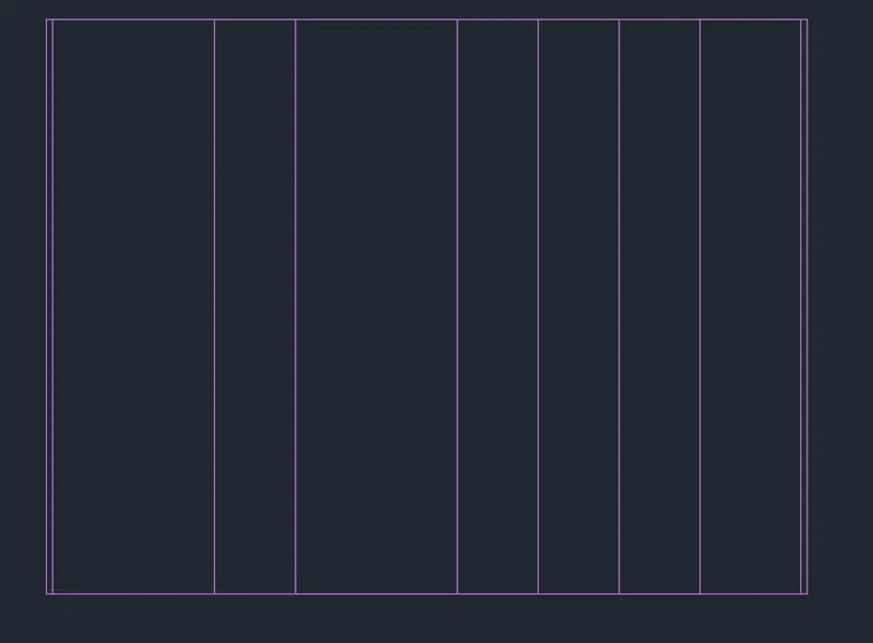
- Command OFFSET
- Select through option and object and specify the offset distance as 290 units as wall thickness for all the 4 sides
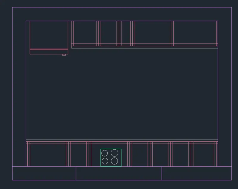
- Select through option and object and specify the offset distance for below counter outer plan at the bottom and top level
- Command Circle
- Specify the center point of the circle and draw a circle of radius for hob area.
Step 4 :
- Command TEXT
- Specify the starting point of the text, enter the height as 100 units and mention the angle as zero degree and enter the text as shown in the layout
- Command Copy
- Select the object and specify the starting point and paste it as per texts given in the layout and rename it.
- Command Hatch
- Specify the object that needs to be hatched and select the STyle as " ANSI32 " and scale as 500 units and selct the wall wherever required this style
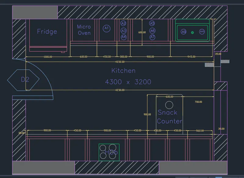
- Command - DIMLINEAR
- Mention the dimensions of each unit that is mentioned in the layout.
Above counter plan:
Step 1:
- Copy the walls from the below counter plan
- Offset of 600mm from the top of the room to draw the platform
- Enter offset distance as per the reference plan
- Command - Text
- Give the dimensions and text wherever required.
The same process is been repeated for the above counter plan, Command - Line, arc,hatch, offset and trim option
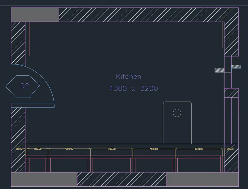
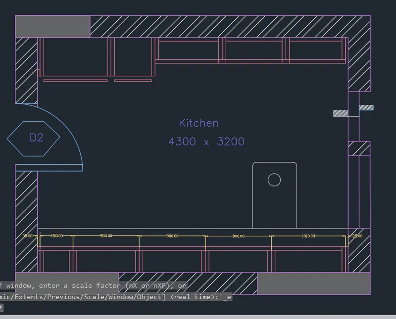
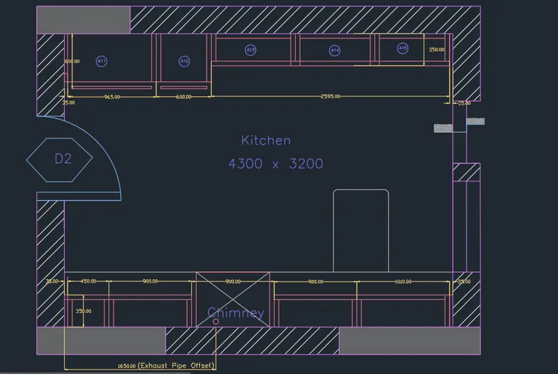
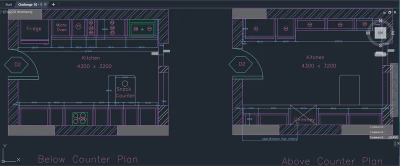
Result : The Layouts of the Kitchen has been created and hatches has been provided.
***********
2. Aim : Create the elevation of the plan apply proper hatch in the walls, doors, windows, and other architectural elements.
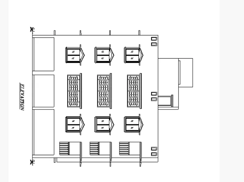
Commands used:
- LINE
- Offset
- Fillet
- Extend
- Trim
- DIMLINEAR
- Hatch
- DIMTEXT
- Copy
- Layer
- Block
Procedure :
Step 1 :
- Command - XLine
- Specify the 1st point and draw a line horizontally as per the walls available
- Command - Offset
- Select the through option and object and specify the offset distance of 230 units for wall thickness.
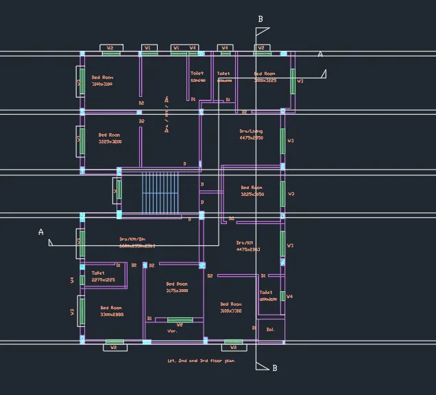
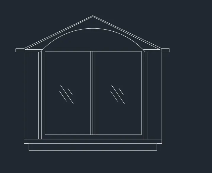
Step 2 : Window
- Command - Rectangle
- Select the dimension option create a rectangle to form a door
- Command - Offset
- Select the through option and object and specify the offset distance to for the outer rectangle
- Command - Arc
- Select the 1st point and end point and draw the arc for the door.
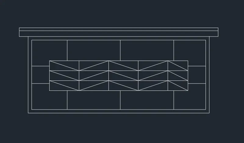
Step 3 :
- Command - Rectangle
- Select the dimension option create a rectangle to form a door
- Command - Offset
- Select the through option and object and specify the offset distance to for the outer rectangle
- Command - Line
- Select the 1st point and draw the outer view for the window
Step 4 :
- Command - Rectangle
- Select the dimension option create a rectangle to form a door
- Command - Offset
- Select the through option and object and specify the offset distance to for the outer rectangle
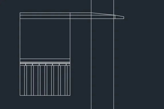
- Command - Line
- Select the 1st point and draw the projections for the window ( Lintels )
Step 5 :
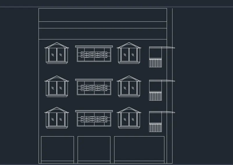
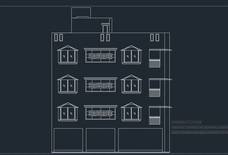
- Command - Offset
- Create basement using this command
- Offest distance for ground floor 2450 , for second and third floor 2850mm
- Offset distance for parapet wall 1000
- Offset distance for OTH 600 and 1200
- Command - Array
- Select the objects (ie) windows and press enter
- Now place the objects in all 3 floors
Step 6 :
- Command Hatch
- Specify the object that needs to be hatched and select the STyle and selct the gradient option, select the wall wherever required this style
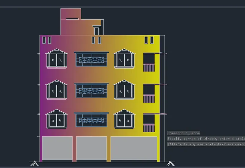
Result : The elevation of the plan with proper hatch in the walls, doors, windows, and other architectural elements has been created.
**************
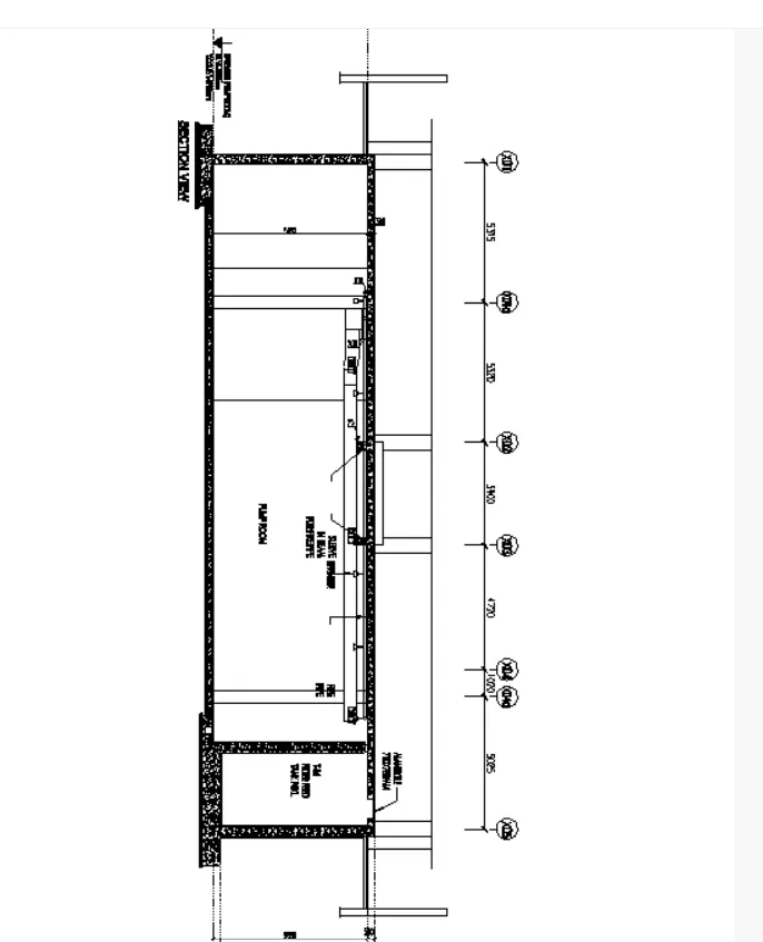
3. Aim : To Create the section view of an industrial building as shown in Figure.
Commands used:
- LINE
- Xline
- Offset
- Fillet
- Extend
- Trim
- DIMLINEAR
- Hatch
- DIMTEXT
- Copy
- Layer
Procedure:
Step 1 :
- Create a new AutoCAD file with imperial settings.
- Command D - units type as "Decimal" (dimension - mm) and set the precision also
- Set the limits with command "LIMITS" enter zoom all.
- Command - UNITS to change the unit option as "Decimal" and set the precision
Step 2 :
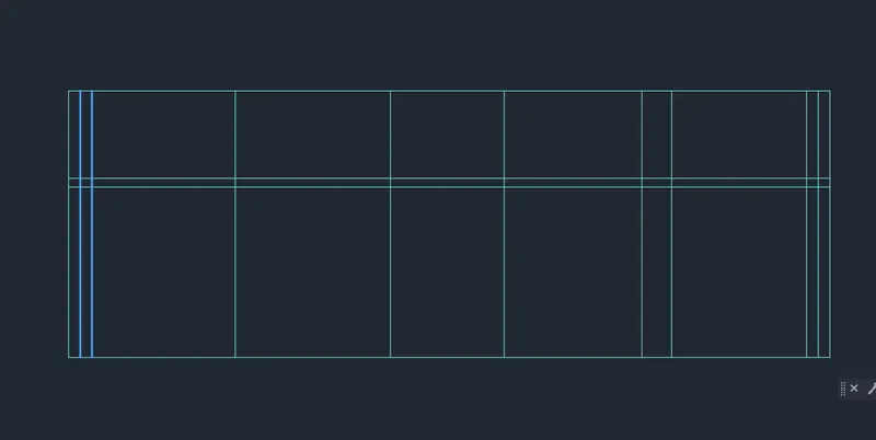
- Command - Xline
- Specify the 1st point and draw a line horizontally and vertically
- Command OFFSET
- Select through option and object and specify the offset distance for the outer wall
- Specify the offset distance of 5315 from left end
- Specify the offset distance of 5320mm
- Specify the offset distance of 3900mm
- Specify the offset distance of 4720mm
- Specify the offset distance of 1020mm
- Specify the offset distance of 5025mm
- Specify the offset distance of 5850mm from bottom end
- Select Home - Layer properties and select the layers for the outer wall and all the items required.
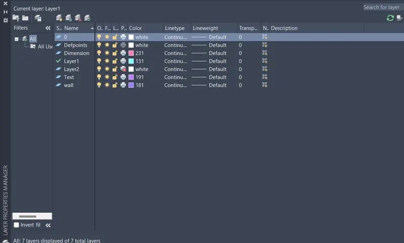
Step 3 :
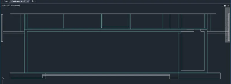
- Command - Line
- Specify the 1st point and draw a line for the filter tank
- Command - Extend
- Select the object and extend the line for the ground level and also for the basement level
Step 4 :
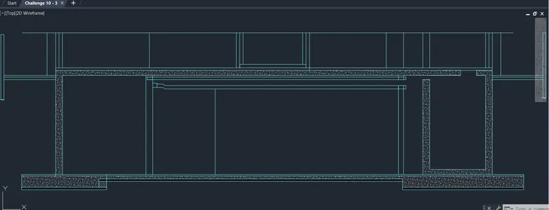
- Command Hatch
- Specify the object that needs to be hatched and select the Style as AR-CONC, select the wall wherever required this style and also specify the hatch scale for about 1 units
- Command Hatch
- Specify the object that needs to be hatched and select the Style as SOLID, select the wall wherever required this style.
Step 5 :
- Command TEXT
- Specify the starting point of the text, enter the height as 100 units and mention the angle as zero degree and enter the text as shown in the layout
- Command Copy
- Select the object and specify the starting point and paste it as per texts given in the layout and rename it.
- Command - DIMLINEAR
- Mention the dimensions of each unit that is mentioned in the layout.
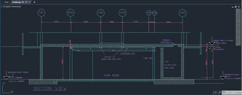
Result : The section view of an industrial building has been completed.