Structural Modelling using Etabs 2018
Structural Modelling using Etabs 2018
AIM:
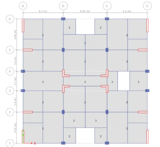
The architectural drawings for a G+7 residential building in zone 5 has been provided. The floor plan is the same for all 7 floor levels. Possible column positions have also been provided. Conceptualize a framing plan layout and then model the building in Etabs. The following architectural drawings have been provided:
- Typical floor plan – The location and thickness of the brick walls and the use of the
space (for estimating live load) can be obtained from this plan - A building section through the staircase and lift core is provided
- Parking layout in the ground floor – the column/shear wall arrangement must not
obstruct entry/exit of vehicles.
The following loadings are to be taken into account: - Brickwall made of AAC blocks
- Finishes – floor tiles of 75 mm thickness
- Live loads as per IS 875 part 2
- Water tank of 20 KL above the staircase at Mumty level
- Lift Machine room at mumty level above lift core
Run a modal response spectrum analysis and check analysis results of the etabs model for inter-storey drift requirements, vertical & planar irregularities, minimum shear wall requirements, maximum axial load ratio for column and shear walls, effective moment of inertia for beams and columns etc.
INTRODUCTION:
ETABS is the abbreviation of " Extended 3D analysis of building system". It is a product of Computers and structures, Inc. Which is recognised globally at the pioneering leader in structural engineering analysis and design software for structural and earthquake engineering.The innovative and revolutionary new ETABS is the ultimate integrated software package for the structural analysis and design of buildings. The latest Etabs offers unmatched 3D object-based modelling and visualization tools, blazingly fast linear and nonlinear analytical power, sophisticated and comprehensive design capabilities for a wide range of materials, and insightful graphic display, reports and schematic drawings that allows user to quickly and easily decipher and understand analysis and design results.
In this challenge we are going to model the g+7 storey building with the give architectural plan.
PROCEDURE:
- Initially open the given architectural plan in AutoCAD and study the plan & locate the positions of beams, column and shear walls.
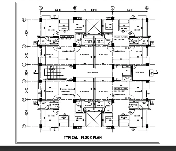
- After done the positioning then the structural plan should be implemented in the Etabs software.
- Now open the Etabs software and click on the new model option
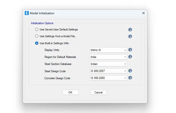
- It will appear a model initialization window, then select the Use Built-in settings with option and fill the units and codes as per the details we used.
- Then again it will appear another window-new model quick template. BY using this template select the grids and storeys and respectively its dimensions also.
- Hence the grid and storey details will appear.
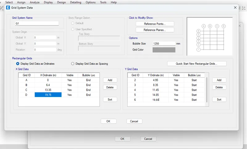
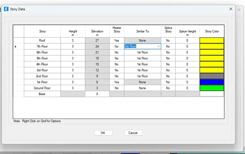
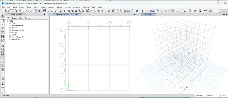
- After that, we have done the material properties. So, to input the material properties go to the Define tab and then select the materials property and then go to the add material property option.
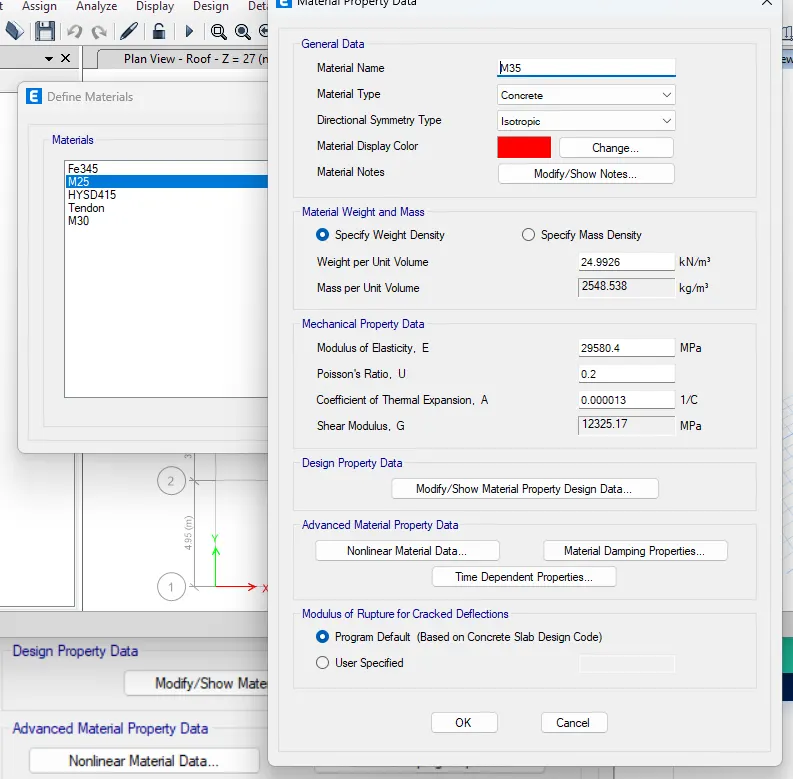
- Creating of concrete material as per the details given
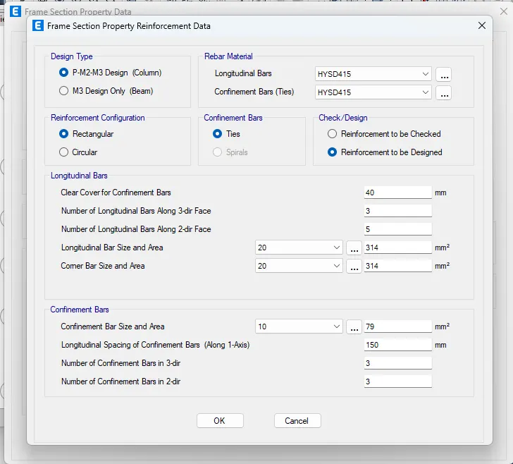
- Now we have to add the frames members to the structure. So, we go define tab --> selection properties--. frames sections.
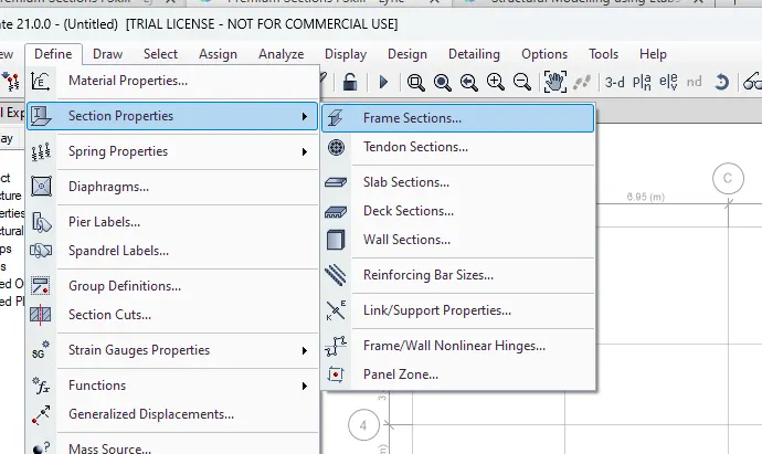
- Hence, the materials are added in the frame window which is shown in the below figure.
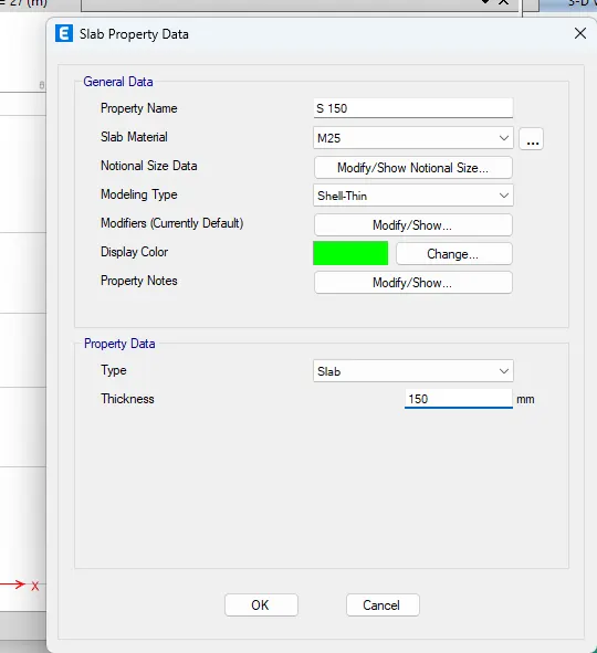
- Now, we have added the slab details. go to define tab- section property-slab sections-slab property data dialogue box opens. In that we have fill the details as per the question.
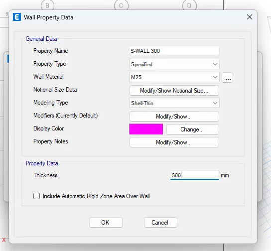
- All the properties for the frame members have added .so, we have to place the structural members, beams, columns, slabs and shear walls.
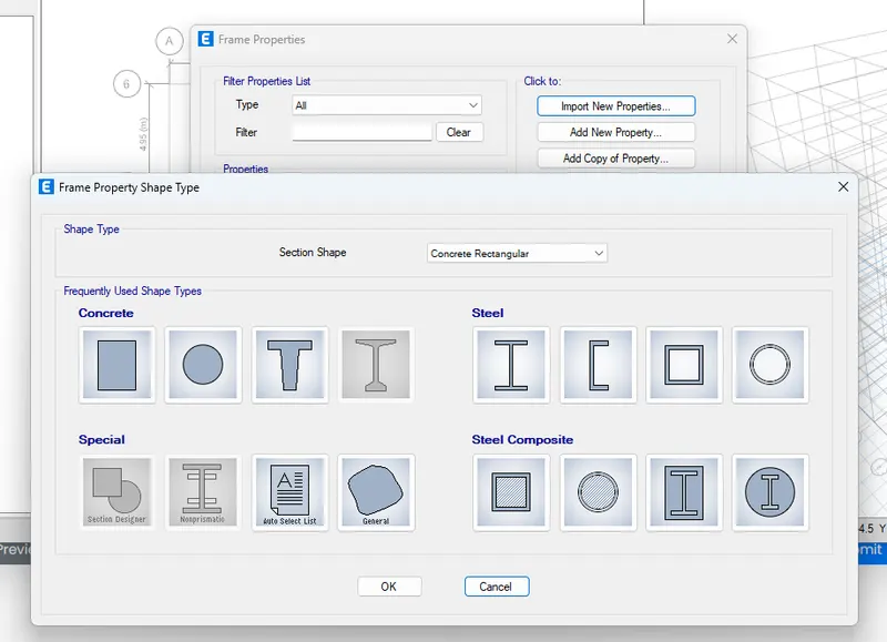
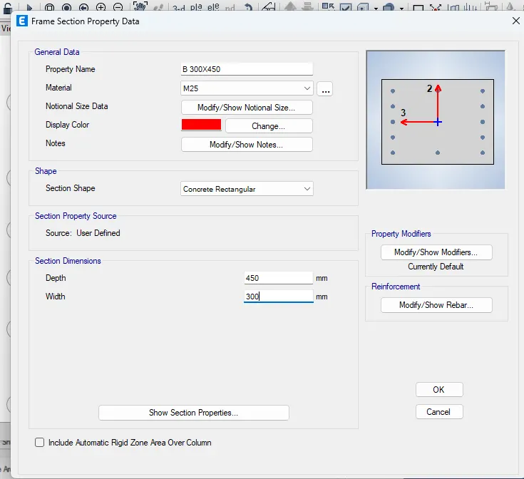
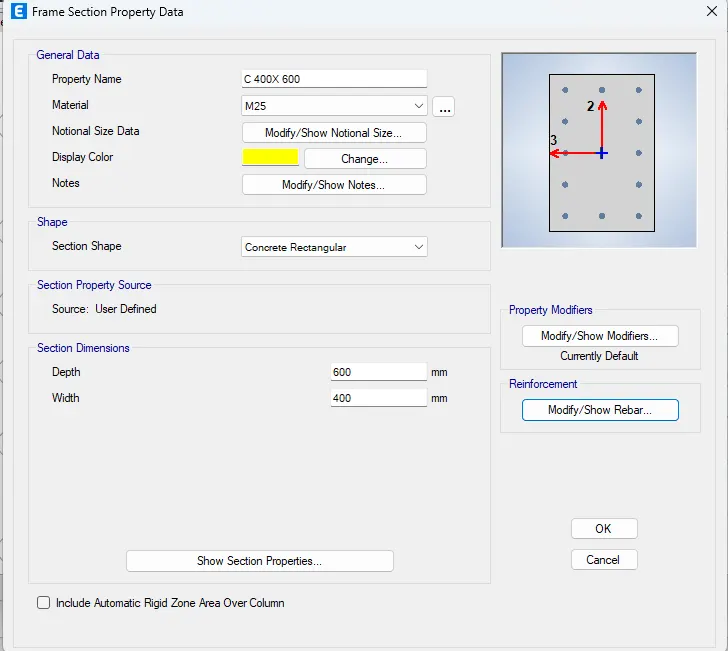
- For adding the frame members to its. there is a tool which is placed left side of the Etabs software.
- With the help of the tools all frame members are added.
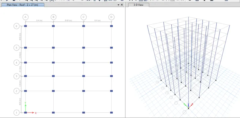
- Firstly, we have placed the columns all over the storeys by taking the quick column section tool. Select the all-column positions, it should be added automatically.
- Next, we have placed the beams by using the quick beam section tool. Make sure that all beams are selected and it in all stories.
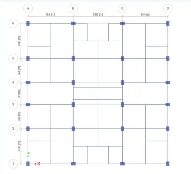
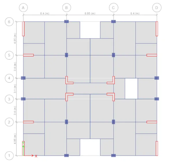
- Similarly, the slabs are also selected. and draw the shear walls as well as make sure that stair case slab is one way slab.
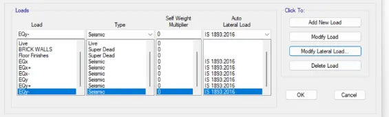
- Now, it’s time to assign the loads on the frames. For, go to define tab-load patterns- Define load patterns window will appear. Initially the dead and live are added on itself. Now we have to added the brick wall loads and earth quakes load in both directions.
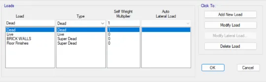
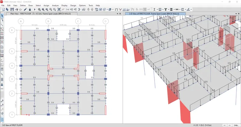
- Now we have provided the mass source value to the seismic weight.as per the required details.
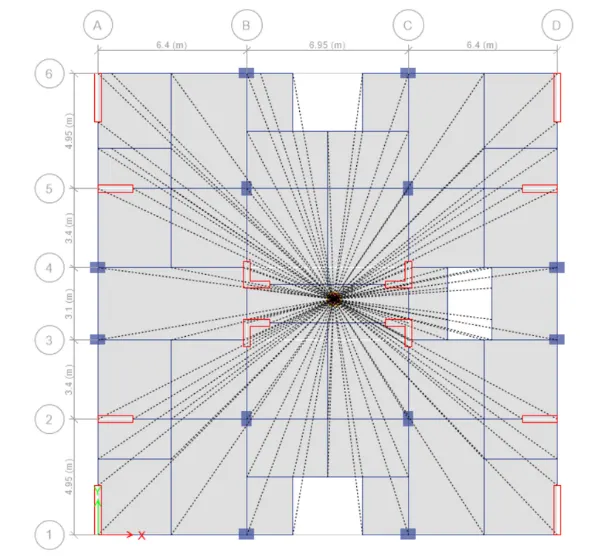
- Now we have created the diaphragm to the structure
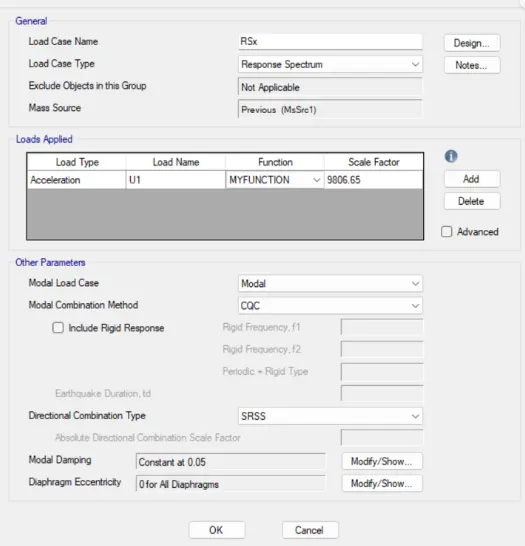
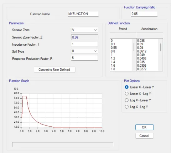
- before doing the load combinations- add the response septum loads- go to define tab- load cases- then add the response spectrum loads in both direction RSx&RSy">RSx and RSy
- After that we need to define the load combinations. For this Go to define tab-load combination and select the concrete frame design select and click ok.
- Then it will generate the automatic load combinations as per the codal provision

- Then add the load to the respectively.
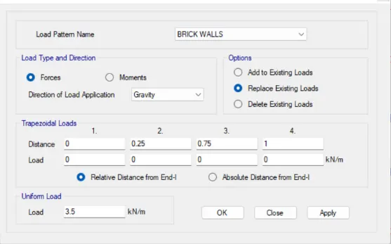
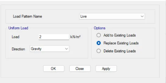
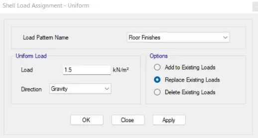
- Assigning the loads for different types of elements.
- Brick wall load-3.5knm
- Floor finish-1.5knm2
- Live load -2knm2
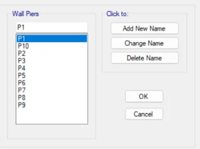
- Before run the analysis make sure that shear walls are assigned by pier labels.
- Finally go to the analyse tab-check model- It is checked for any errors and warnings
- Now the model is ready for the analyse.so we can run analysis.
- Hence run analysis has been completed.
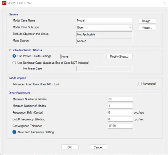
- MODAL PARTICIPATION RATIO CHECK
- after the completion of analysis. Go to the display-show tables- analysis results-structural output-modal information - modal mass participating ratio.
- Now satisfied the modal participation of translational mode- first two fundamental modes should be greater than the transitional mode (third one).
- BASE SHEAR CHECK AND SCALING.
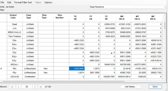
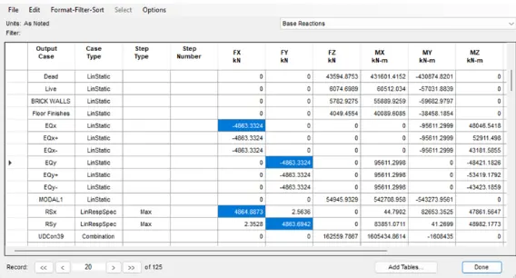
- Now, go to the base reactions. Go to the display-show tables-analysis result-structure output-base reactions.
- EQx=1159.66 kn & RSx=1163.24
- hence the scale factor is 1159.66/1163.24 = 0.9806
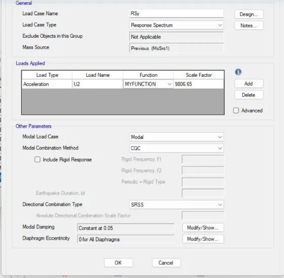
- EQy=1159.75 kn & RSy = 1160.56kn
hence the scale factor is 1159.75/1160.56 = 0.9806
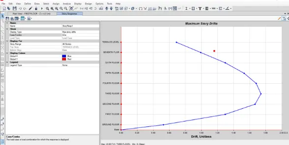
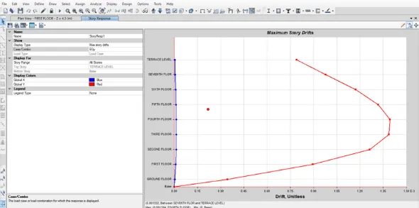
- CHECK FOR INTER-STORY DRIFT
- As per the codal provision os IS 1893: 2016 it does not exceed the 0.004, we obtained 0.0023. so hence safe..
- Now Go to define and Diaphragm the model
RESULT:
The structural model is completed with provisions of IS 1893 and IS 13920. and checked for the following
- Run a modal response spectrum analysis and checked the analysis results of the etabs model for
- Inter-storey drift requirements
- Vertical & planar irregularities
- Minimum shear wall requirements
- Maximum axial load ratio for column and shear walls
- Effective moment of inertia for beams and columns etc.
Story Drift