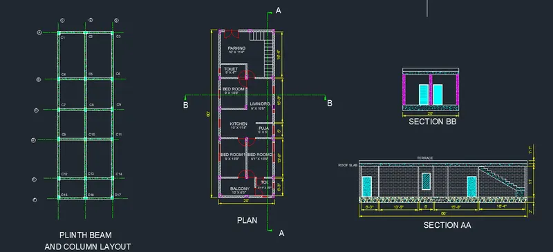
Project 1 _Creating an Architectural plan for the provided plot size and develop relevant basic structural drawings
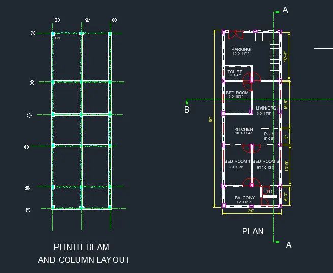
AIM : Design and Draft a layout of a residential building with the following details:
a. Plot Size: 60’x20’(18.3m x6m)
b. Orientation- Facing East
c. Develop the following: 1. Architectural Drawing (Floor Plan, Elevations, and Sections) 2. Structural Drawing (Column, Bean, Footing Plan)
INTRODUCTION : A (60' X 20')Residential Building is designed with Architectural and structural drawing by using following command
- Line
- Rectangle
- Polygon
- Circle
- Trim
- Mirror
- Offset
- Array
- Rotate
- Move
- Erase
- Dimension
- Text
- Fillet
- Layers
Procedure :
PROCEDURE:
- Open new AutoCAD drawinf
- Set dimension setting as Architectural
- Set angle measure as East and press next
- Keep ortho , Object snap >ON
- Keep snap grid >off
- Units to scale inserted content > feet & inches
- Take xline command
- Put xline horizontal and xline vertical
- Trim the negative coordinates
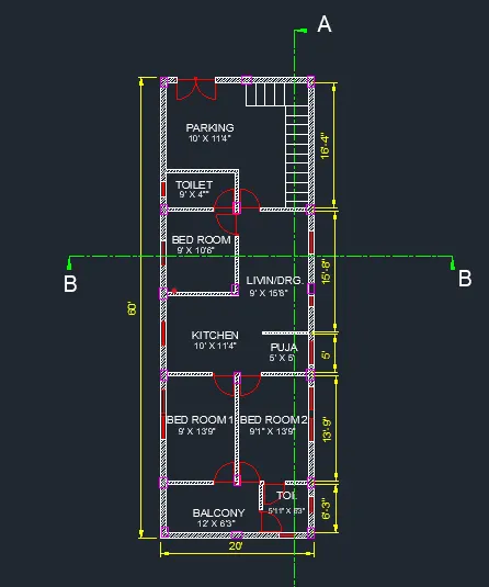
- Make outline of the House Plan by using Line command with dimensions 60' and 20' inches
- Give the offset of 9" to make external wall thickness
- Offset the horizontal line at distance of 6'3" , then make a inner wall offset of 4.5"
- Now again offset each line to the next line at a distance of 13'9" , 4.5" ,5',13'9", 4.5" , 10'7.5", 4.5", 7'3", 9".
- using dimension command measure the required dimensions.
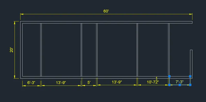
- For internal wall give offset of 4.5" inches and for external wall give offset of 9" inches
- Offset the vertical line at a disctance of 6', 9'1", then 9' including interior wall.
- Give offset to each above vertical line as per their wall thickness
- Give the another required offsets by using offset command
- Leave the spaces for doors
- Take trim command and trim the required lines
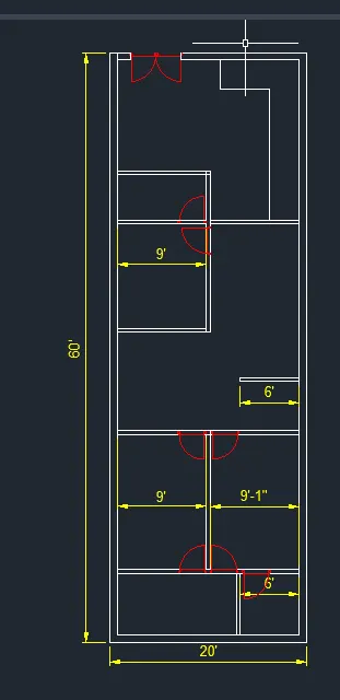
- Click on layers properties
- Click on new layers
- Give the layer name > wall
- Turn the layer > on
- Set Unlock
- Select layer colour> white
- Similarly, use this above process to provide the layers
- The layers which are assigned are shown as below
- Using line command
- Provide the window and doors as per their respective dimensions
- Using HATCH command provide hatching in the walls, after using region command
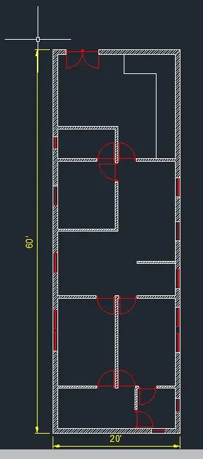
- Now provide text and other marking of sections AA and section BB
- Use Array command and make stairs,
- use layer command with continious command , with green colour. mark section AA ans section BB
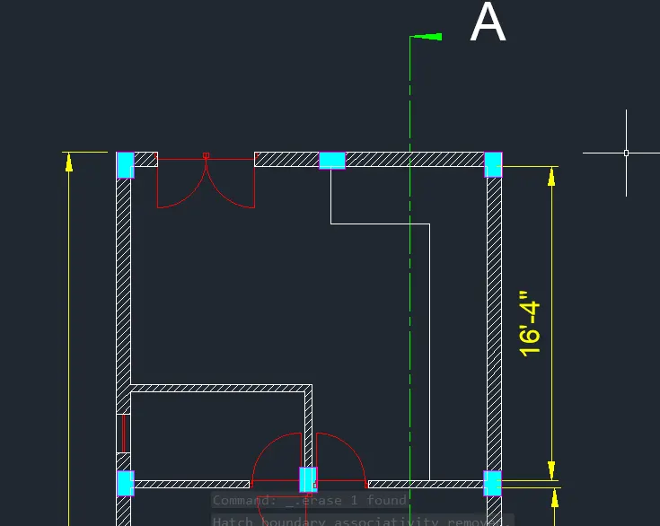
- With Rectangular command make columns throughout the floor plan
Section AA
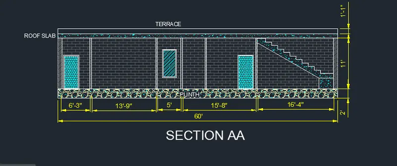
- Make the out line of House , specify the lenght of house as per the section 60' and height 11'
- Now offset the line as per the distance of walls in the plan, make doors and windows
- now using region command make the required region for the hatching
- Now hatch the Plinth are with Concrete hatching and window and doors with grading of glass and steel
- Using Dimension command, show the dimensions od the section
- Use Text command and provide all the specification of the section
- Now use the hatching in the stairs.
Section BB
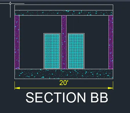
- For this section draw a line of 20' and height of 11' feet
- Make doors and walls as per dimension
- Hatch the walls and plinth area, also doors
- mark the dimensions
PLINTH and Column Beam LAYOUT
- Make the similar plan and provide the columns within the plan
- Place all the columns on the plan drawing
- Hatch the walls and columns by using Hatch command
- Now draw the continious line from layers throught the column passage
- Mark the columns as C1, C2, C3, C4 etc.
RESULT :