Structural Modelling using Etabs 2018
Aim: To conceptualize a framing plan layout and then to model the building in Etabs
Procedure:
- Open ETABS and select New Model option from the File menu
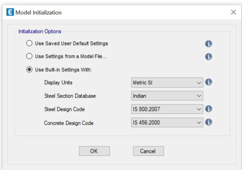
- Now set the Use Built in setings with Options
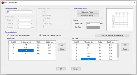
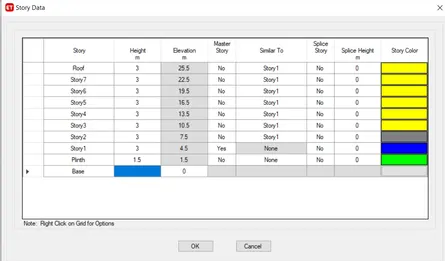
- Now set the Grid systems data and add 7 storeys with an addition of plinth
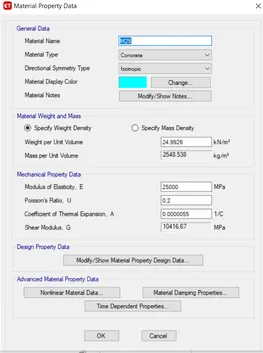
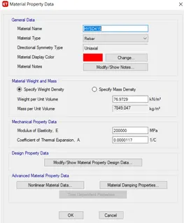
- Now select the Material properties from the Define menu and add New material as concrete M25 and Rebar HYSD 415 , 500
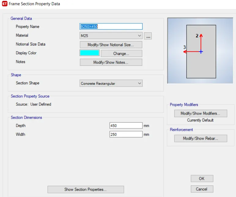
- Now select the section properties and select the frame section, now select Add new property, select the shape and add beam of required size (250*450)
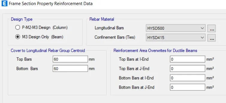
- Now select Modify/Show Rebar option and select M3 design only , and select Longitudinal bars with HYSD Grade 500 and the confinement bars(ties) with HYSD Grade 415
- Now again select the section properties and select the frame section, now select Add new property, select the shape and add beam of required size (300*500)
- Now select Modify/Show Rebar option and select M3 design only , and select Longitudinal bars with HYSD Grade 500 and the confinement bars(ties) with HYSD Grade 415
- Now select the section properties and select the frame section, now select Add new property, select the shape and add column of required size (400*400)
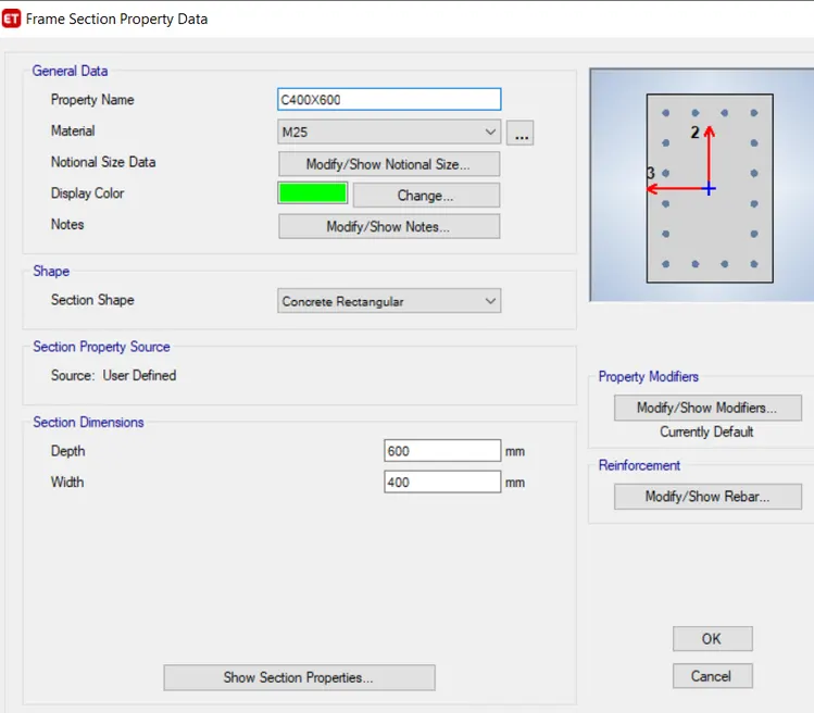
- Now again select the section properties and select the frame section, now select Add new property, select the shape and add column of required size (400*600)
- Now from the Define menu, select Section properties and select Slab section
- Select Modify/Show property, give a new slab name and mention the thickness as 125mm and slab material as M25 and click ok
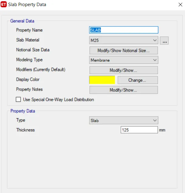
- Now define a new slab for the staircase, with thickness 200mm and slab material as M25.
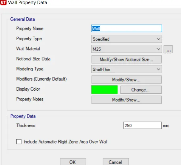
- Insert 250mm thickness in the wall property data and click ok with the wall material as M25
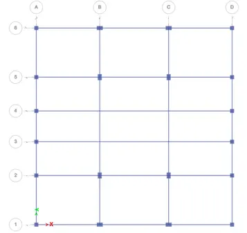
- Using Quick draw columns, draw the columns
- And now use quick draw beams, draw the beams. Now draw the secondary beams using Quick draw beams option
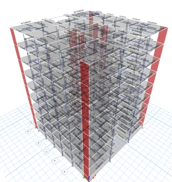
- Now add the shear walls at appropriate location as given in the plan.
- Now using Quick draw floor/wall option, draw the slabs
- Now select the base joints and select Restraints from Joint option of Assign menu, and fix the joints and click ok
- Now from the define menu, define the load patterns as Live load, dead load, brickwall load, earthquake loads.
- Now select the frame loads from the assign menu, and slect Distributed loads, and take a uniform load of 3.5 KN/m and close it
- Now from the Assign option, select the shell load and select Uniform and apply 3KN/m^2 for staircase, life etc
- Now from the Assign option, select the shell load and select Uniform and apply 2KN/m^2 for the rest of the building
- Now from the Define menu, select mass source and add the load patterns
- Now from the Select option of the Select Menu, select Object type and select the floors, and click select and then click,
- Select the shell option and select Diaphragms from it, select D1 and click on the apply button and close
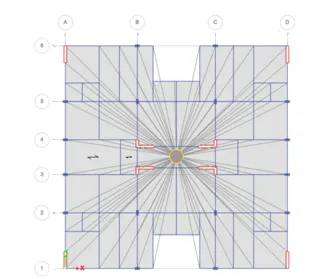
- Now from the Assign Menu, select Pier label option from the shell option
- Now from the define option, select the load combination and select Add Default Design combos
- Now select the concrete frame design and concrete shear wall design in the Add default design combinations
- Now from the Define option, select Modal cases, and give modal case names as Modal 1 and give the maximum number of modes as 20
- From the Analyze menu, select check model, and now the warning tab appears
- Now from the Define option, select Response spectrum and choose IS 1893:2016 .
- Now click on Modify / show spectrum option, and give an identical function name.
- From the Define menu, select Load cases and select Add new case
- Now from the Analysis menu, select Run analysis
- Now select the Design menu, select the concrete frame design and select Start design check
- Now select the Design menu, select the concrete slab design and select Start design check
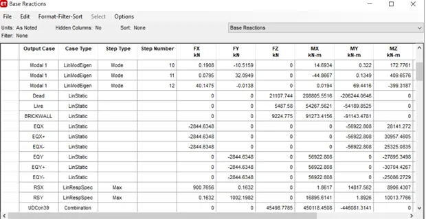
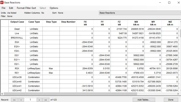
- From the Display Menu, select Show tables and select Base reactions and click ok
Calculation
- To check if the EQ is closer to RS, we use (EQ/RS)
- Now the structure is reanalysed and checked and found that EQ is almost equal to RS.
- We have to check for both EQx, RSx and EQy, RSy
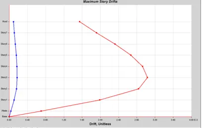
- Now again select the Display menu and select Storey Response plot and select Inter storey drift(RSx) and then for (RSy). The storey response for maximum storey drifts at X and Y directions should not be more than 4%
- Now again take the Display menu and select show tables and select Modal Participating mass ratio and click ok
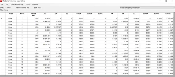
- Now from the Display menu, select Force/ Shear diagram and select Shell stresses/ force
Result: Conceptualized a framing plan layout and then modeled the building in Etabs and analysis are done