Structural Modelling using Etabs 2018
For designing a building in ETABS software,initially we have to create a building where the basic step to continue with it is to create the grids and stories.
Basing upon the architectural plan,we draw few columns and shear walls,where basing upon the column positions,we form the grids.
So basing upon the distance between them,we create the grids as shown below.
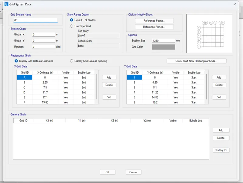
We then create the stories where we where metioned that the building comprises 7 floors along with the Cellar where we even keep the head room above the terrace for the stairway and a lift room and a water tank above the head room.
So,along with the 7 floors above the Cellar,we form the Terrace and Water Tank Levels.
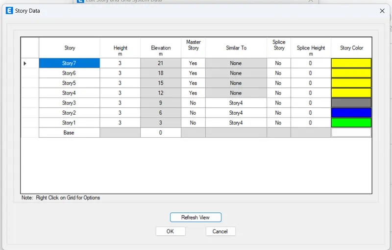
After the creation of the grids and stories,we continue with the defenition of materials where we use these materials for the creation of the materials where ultimately we use these materials for the creation of the components which will be leading to the creation of structure.
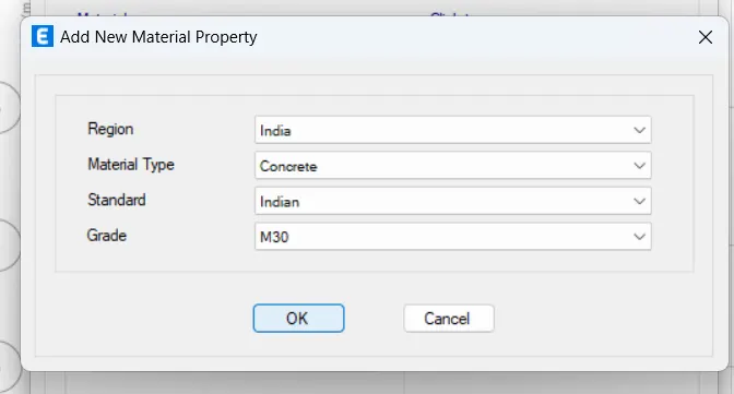
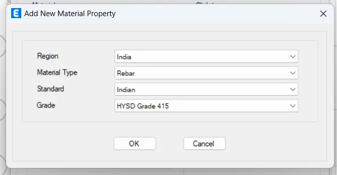
To create materials,we go to Define Tab>Material Properties.
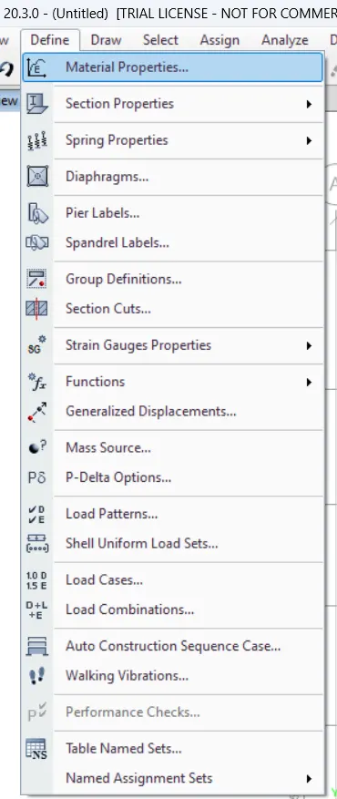
We then click on Add New Material...
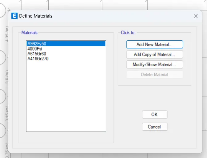
And select the relevant details as shown.
With the creation of the materials,we then go to the creation of the components.
We then go to Define Tab>Section Properties>Frame Sections...
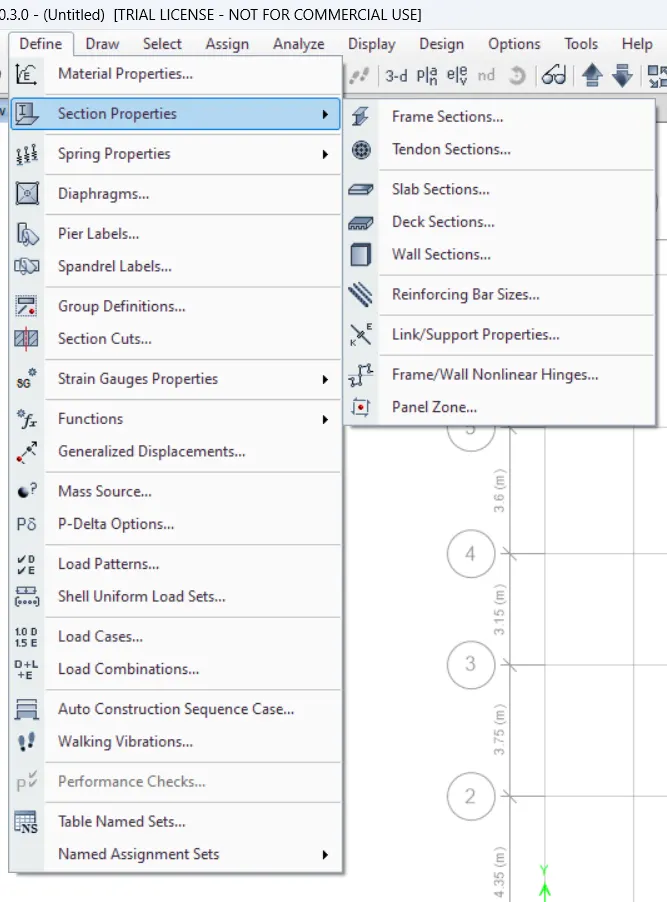
We select the Frame Sections... option for the creation of the frame components i.e.,columns and beams.
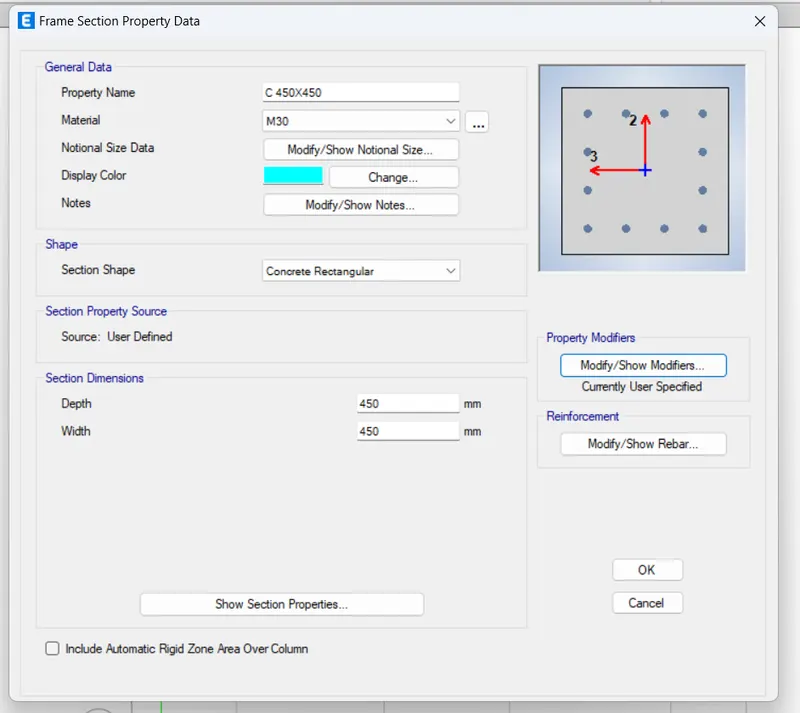
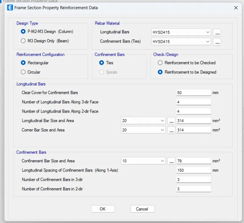
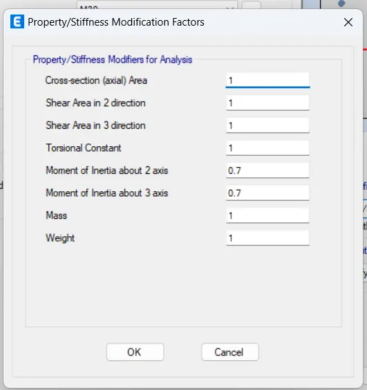
We create the column as shown where we take the Moment of Interia about 2 and 3 axis as 0.70!
Where for the column and beam creation,we select the Concrete Rectangular option.
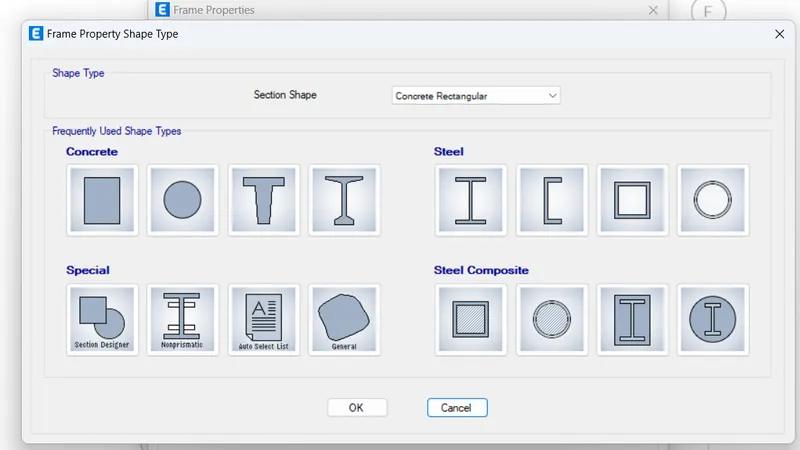
In the similar manner,we create the primary beam aswell as the secondary beam.
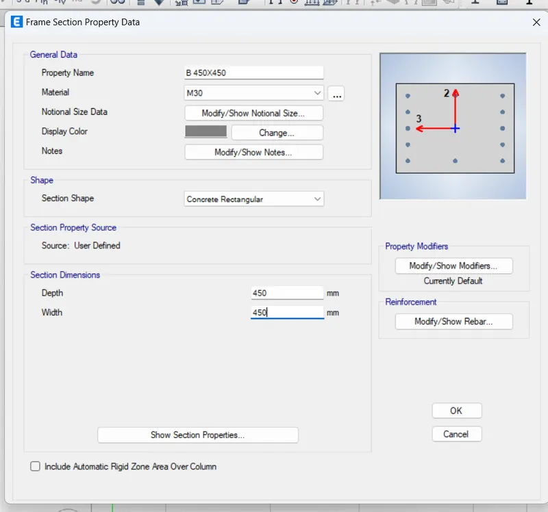
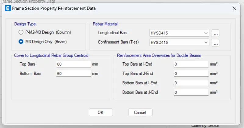
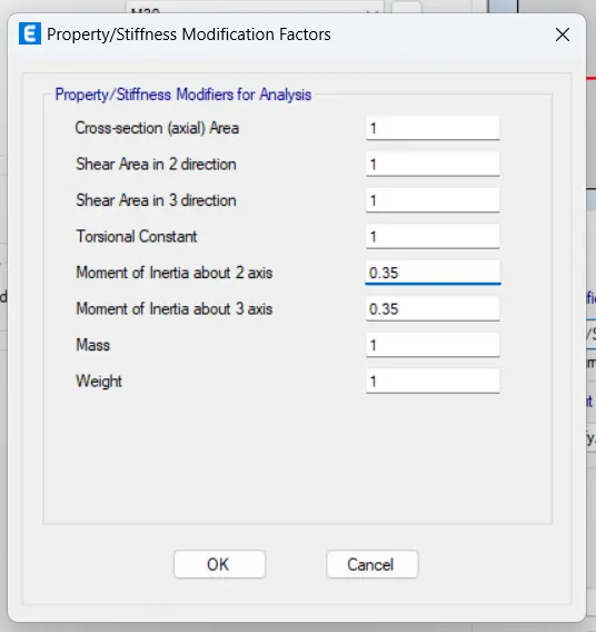
We create the beams as shown where we take the Moment of Interia about 2 and 3 axis as 0.35!
In the same manner,we create the slab and shear wall.
We then go to Define Tab>Section Properties>Slab Sections...
Where we select the option of Slab Sections... for the creation of the slab.
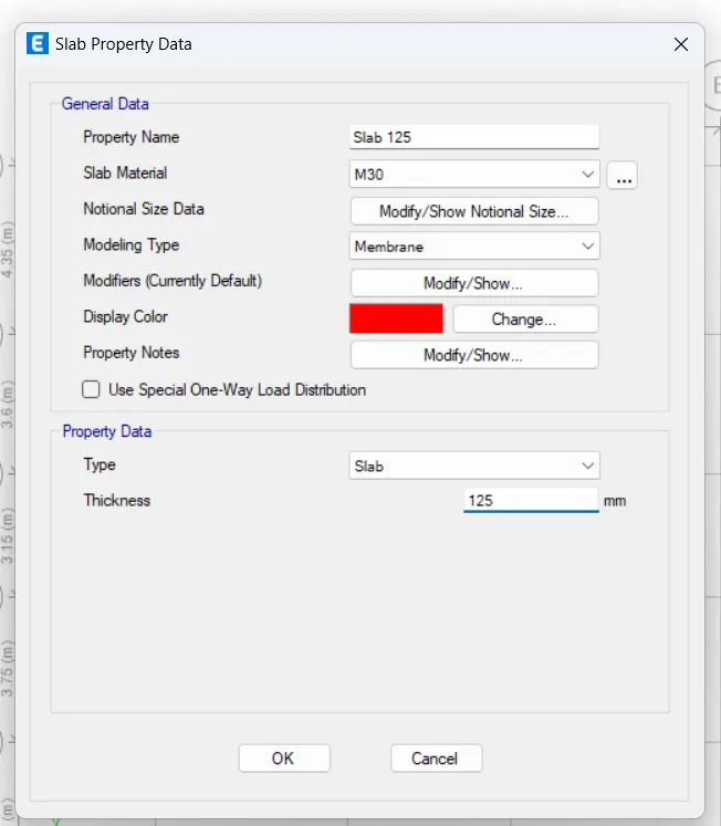
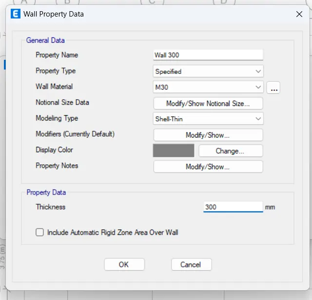
We then go to Define Tab>Section Properties>Wall Sections...
Where we select the option of Wall Sections... for the creation of the shear wall.
We then draw the required components to form the structure as shown.
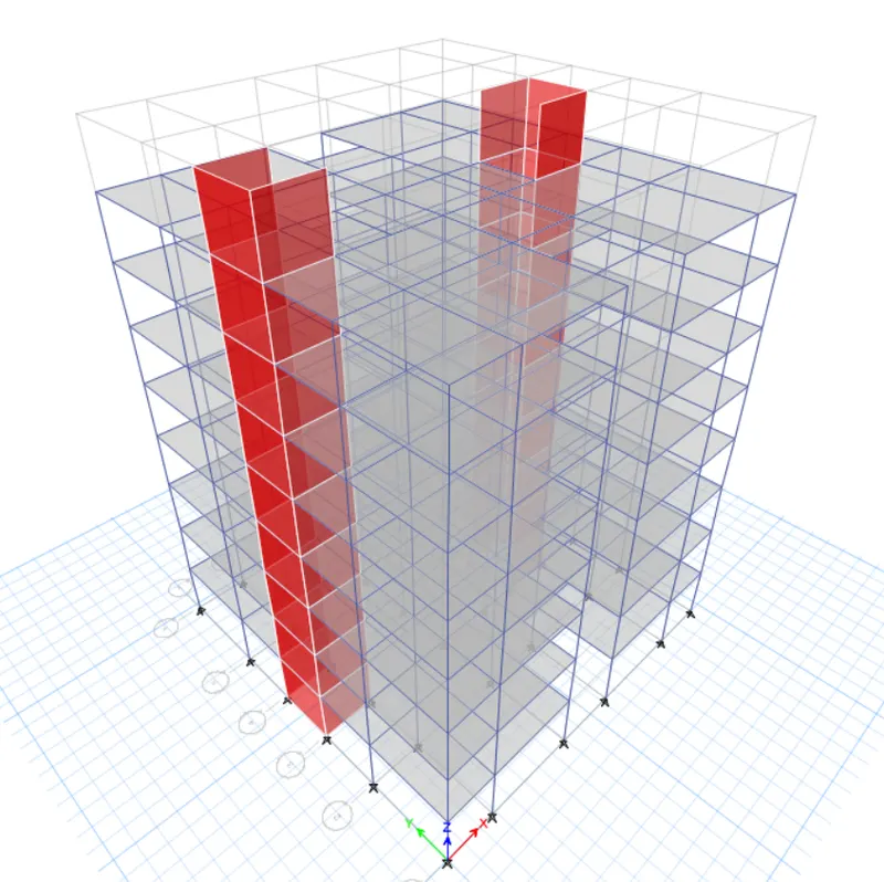
So the structure includes the components as,
- Column Size=450 X 450 mm
- Primary Beam Size=450 X 450 mm
- Secondary Beam Size=300 X 450 mm
- Slab Thickness=125 mm
- Shear Wall Thickness=300 mm
Once the structure is formed we go with the loads.
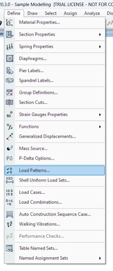
Initially,we have to create the loads,where we go to Define Tab>Load Patterns...
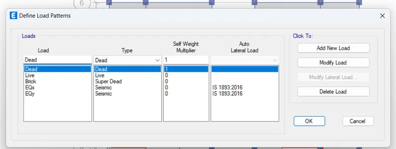
Where we add the Live Load,Dead Load,Brick Load and the Earthquake Loads as shown.
After the definition of the basic required loads,we have to create the load for the earthquake,we we go to Define Tab>Mass Source...
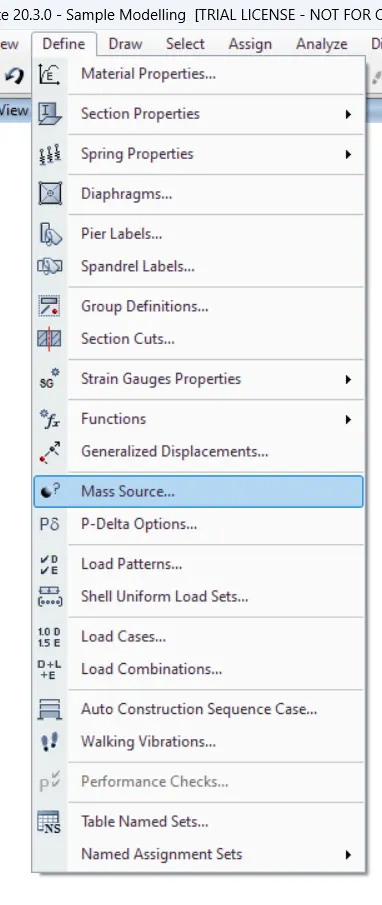
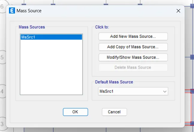
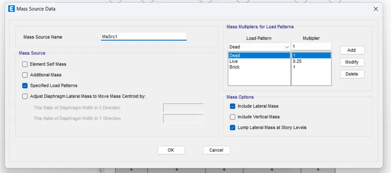
And select the inlcuded loads which act during earthquake.
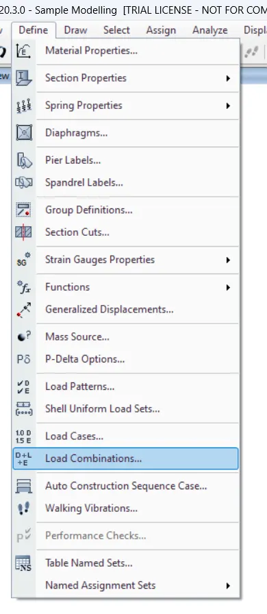
We then create the load combinations.where we go to Define Tab>Load Combinations...
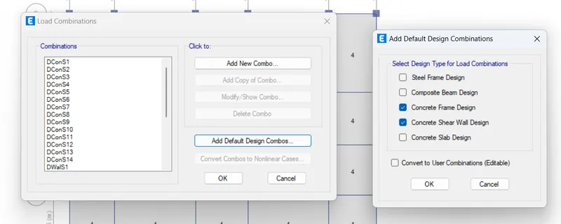
Here,we select the Concrete Frame Design and Concrete Shear Wall Design as we even use the shear walls in the structure.
We then assign the loads,where before the assignment of the loads,we do select the components as per the requirement.
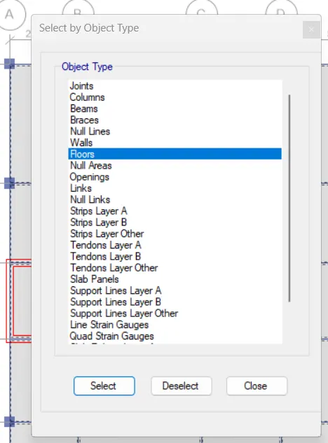
We go to Select Tab>Select>Object Type...
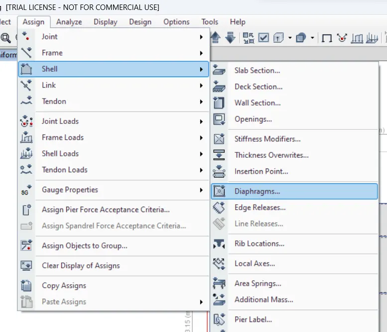
We then go to Assign Tab>Shell>Diaphragms...
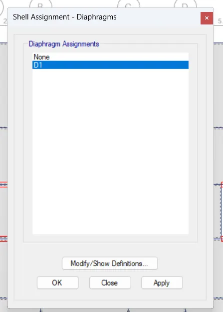
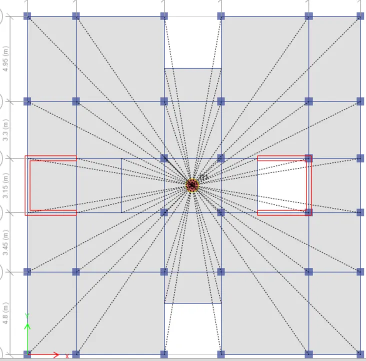
And select the respective Diaphragm.
We then assign the loads to the beams available,where we go to Select Tab>Select>Object Type... and select the Beams option where we then go to Assign Tab>Frame Loads>Distributed...
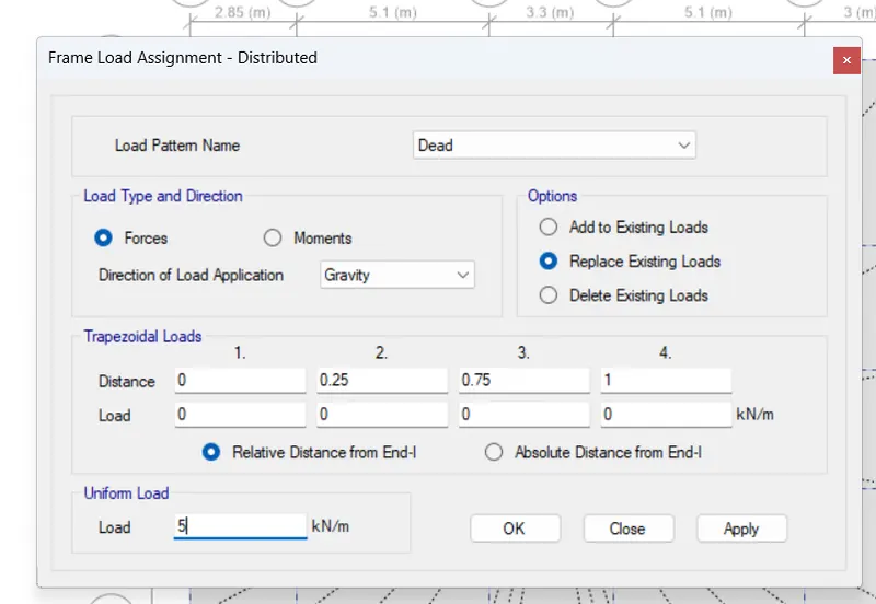
Where we assign the brick load to the beams.
And in the similar manner,we do to the same for the Slab.
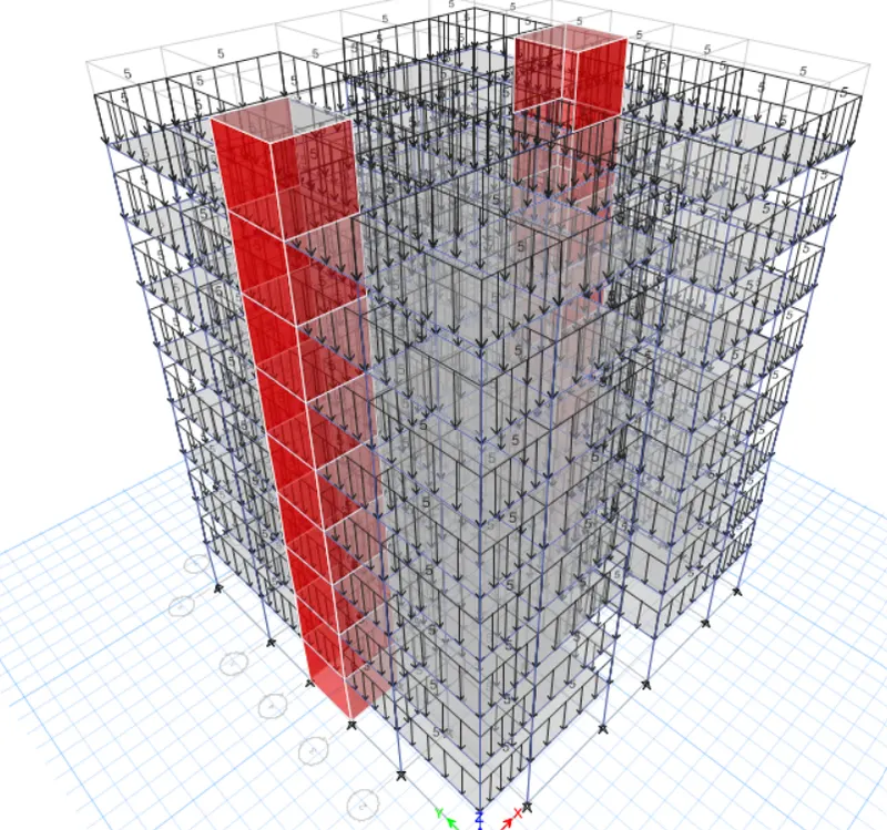
Where the loads we add are the,
- Brick Load=5 KN/sq m
- Live Load=2.5 KN/sq m
- Floor Finish Load=1.5 KN/sq m
- Water Tank Load=200 KN
We then run the analysis of the structure.
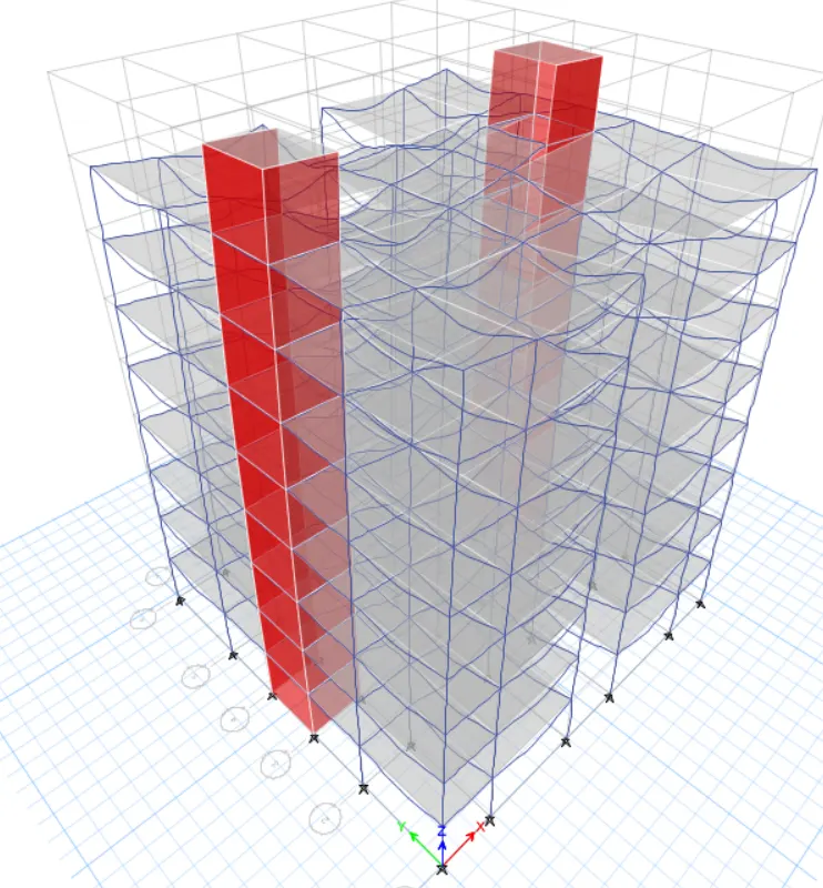
Inter Story Drift
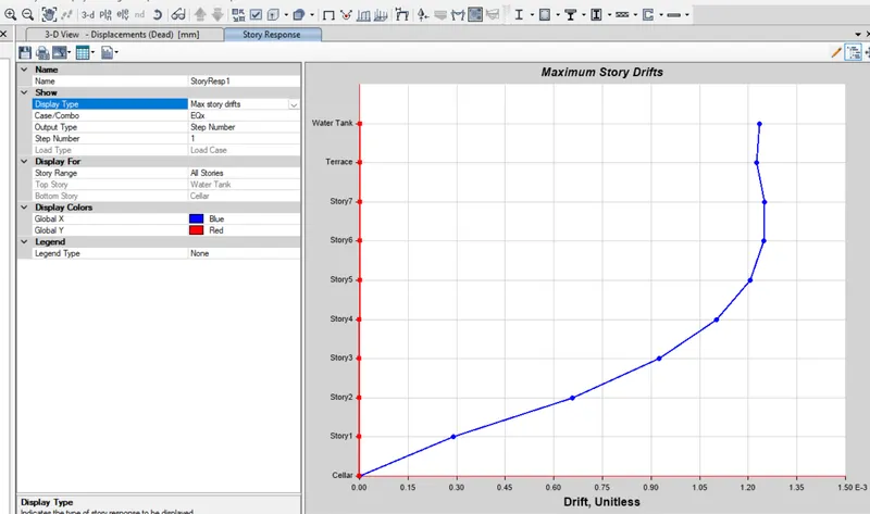
After the analysis of the structure we go for the Display Tab>Story Response Plots...
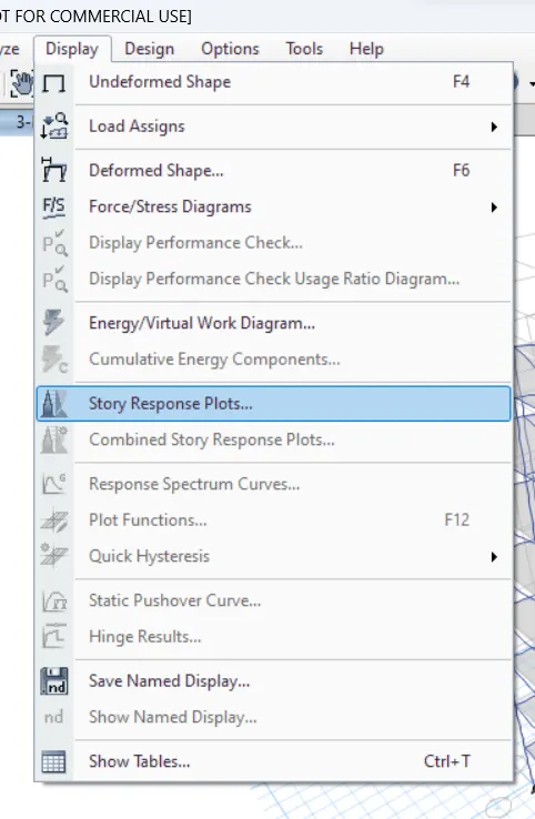
Where we select the option of Max Story Drifts and EQx load type.
Where we can find the value of the building as 0.00125<0.004!
Hence,the building is safe as per this.
Time Period
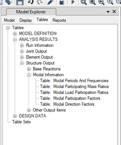
For us to get the various time periods,we then go to Model Explorer Tab>Tables>Analysis Results>Structure Output>Modal Information>Modal Periods and Frequencies.
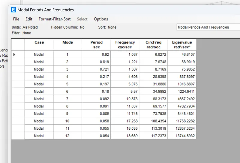
And we can find that the first and the second are near by and we can't find any much variation between those.
And even the third value is less than the second and the first value.
So,the building is safe.
Vertical and Planar Irregularities
As per the elevation,we can find few vertical irregularities in the building.
Firstly,we can find the tank on the head room of the stair case where its present near to one edge of the building making in unstable.
Secondly,the stair case present in at one edge of the building but the lift room is not present on the opposite edge but it is present in the middle making it strucuturally not symmetrical.
As per the plan,we can find few planar irregularities in the building.
Firstly,we can find the plan symmetrical in the horizontal direction but it's not symmetrical along the vertical direction where we can find the study room on one side as an extra.
Shear Wall Requirement
As per the codal provisions,we do require a minimum shear wall area of the 2% of the total build up area,where here we are very near to it but due to the architectural conditions and the parking faculities to be provided we are unable to satisfy the as on requirement of it.
Structural System
As we can find that the most of the base shear is being taken by the shear wall alone,we can't conclude that the structural system as the dual system.