Structural Modelling using Etabs 2018
AIM
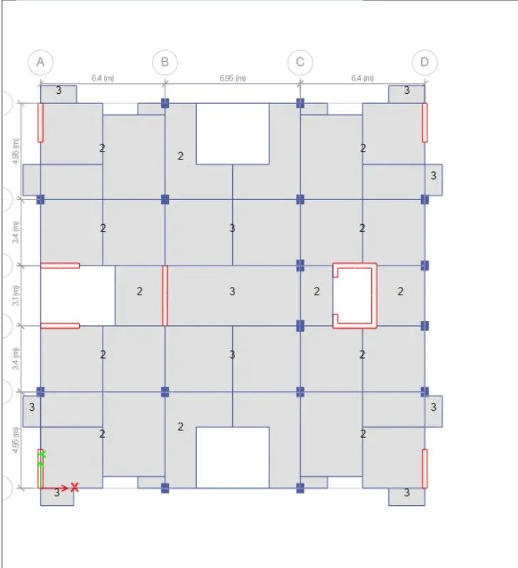
The architectural drawings for a G+7 residential building in zone 5 has been provided. The floor plan is the same for all 7 floor levels. Possible column positions have also been provided. Conceptualize a framing plan layout and then model the building in Etabs. The following architectural drawings have been provided:
- Typical floor plan – The location and thickness of the brick walls and the use of the
space (for estimating live load) can be obtained from this plan - A building section through the staircase and lift core is provided
- Parking layout in the ground floor – the column/shear wall arrangement must not
obstruct entry/exit of vehicles.
The following loadings are to be taken into account: - Brick Wall made of AAC blocks
- Finishes – floor tiles of 75 mm thickness
- Live loads as per IS 875 part 2
- Water tank of 20 KL above the staircase at Mumty level
- Lift Machine room at mumty level above lift core
INTRODUCTION
ETABS is an engineering software that is used for multi-story building analysis and design. Modeling tools and templates, code-based load prescriptions, analysis methods and solution techniques, all coordinate with the grid-like geometry unique to this class of structure.
Here we are modeling and analyze a G+7 residential building in zone 5 using ETABS
PROCEDURE
Step 1:Open ETABS software
Open a new model
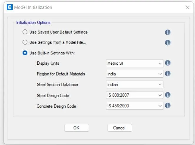
Step 2:Select Custom grid spacing
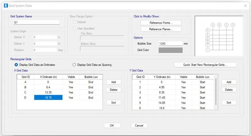
Select ‘edit grid data’
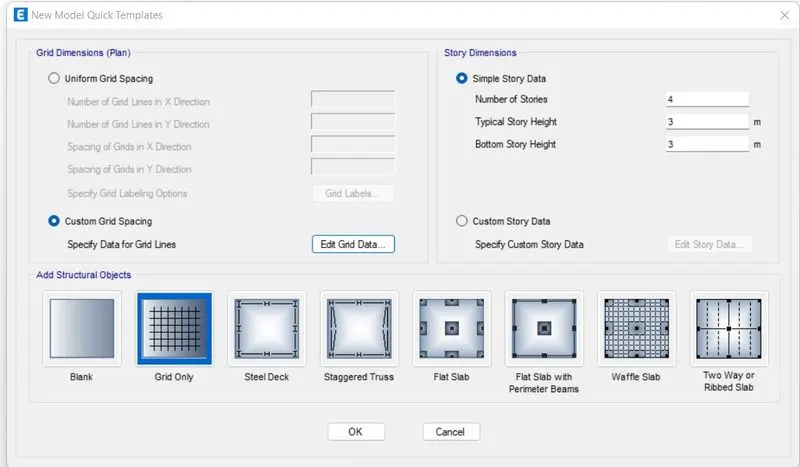
Step 3:Select story data
Select edit story data
Step 4:Select story 3-right click -select add story-keep existing story height
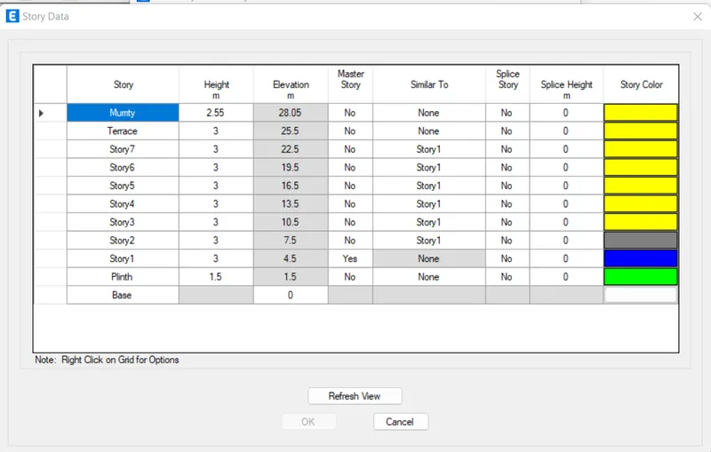
Step 5:Select story 1 make it master story
Make all other stories similar to story 1
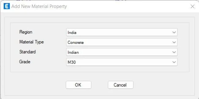
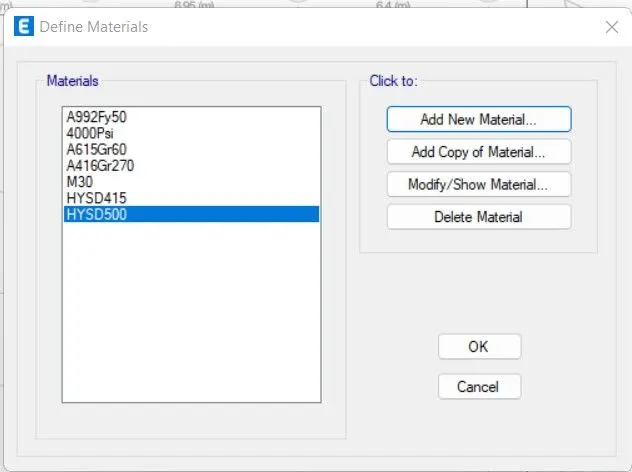
Step 6:From define tab select material property
Add M30 concrete and HYSD415 and HYSD500 rebar
Step 7:From define tab select section properties
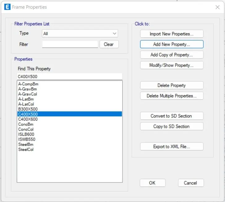
Then select Frame sections -Add new sections
Add columns and beam
Step 8:From define tab select section properties
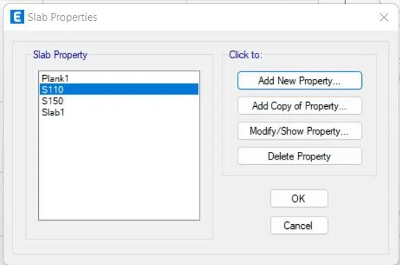
Select slab sections
Add new property
Add slab properties
Step 9:Select quick draw columns
Select all stories
Select the column size
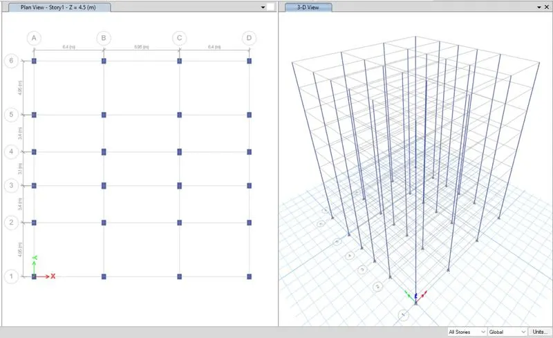
Step 10:Select quick draw beams
Select all stories
Select the beam size
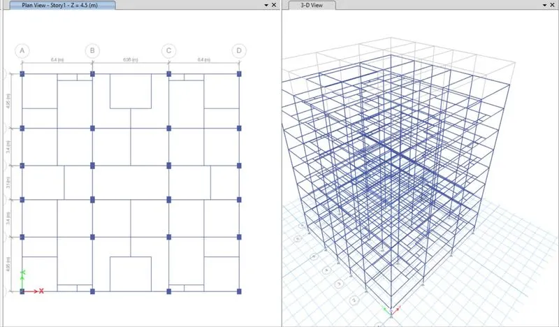
Step 11:Draw shear walls
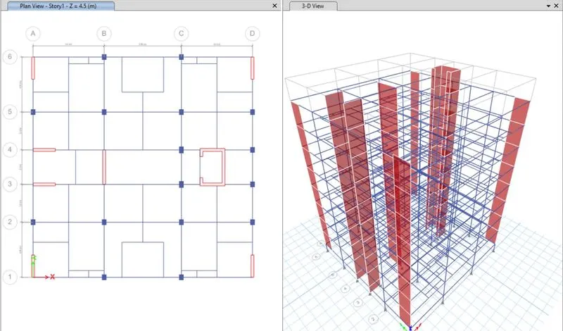
Step 12:Draw floors and cantilever slabs
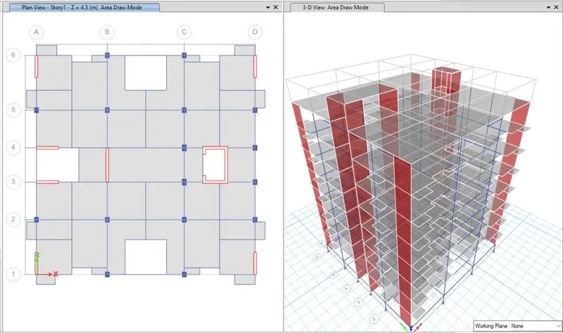
Step 13:Select base level and assign joints as fixed
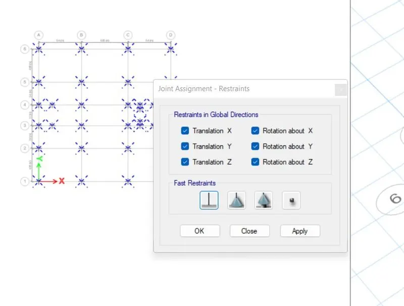
Step 14:Select define
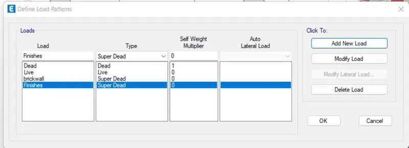
Select load patterns
Add load patterns
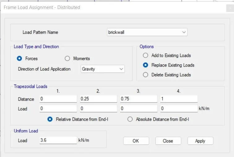
Step 15:Select the beam with brick wall and assign the load
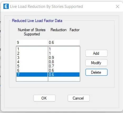
Step 16:Select Design
Live load reduction factor
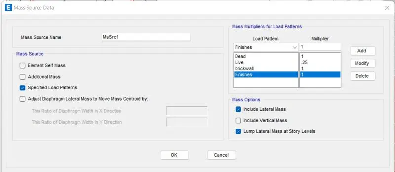
Step 17:Define-Select mass source
Click on modify/Show mass source
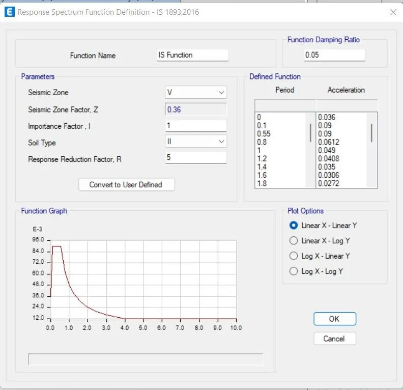
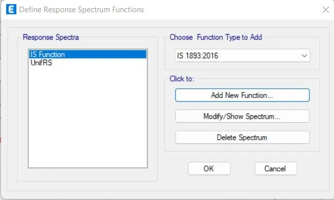
Step18:Define-function-Response spectrum
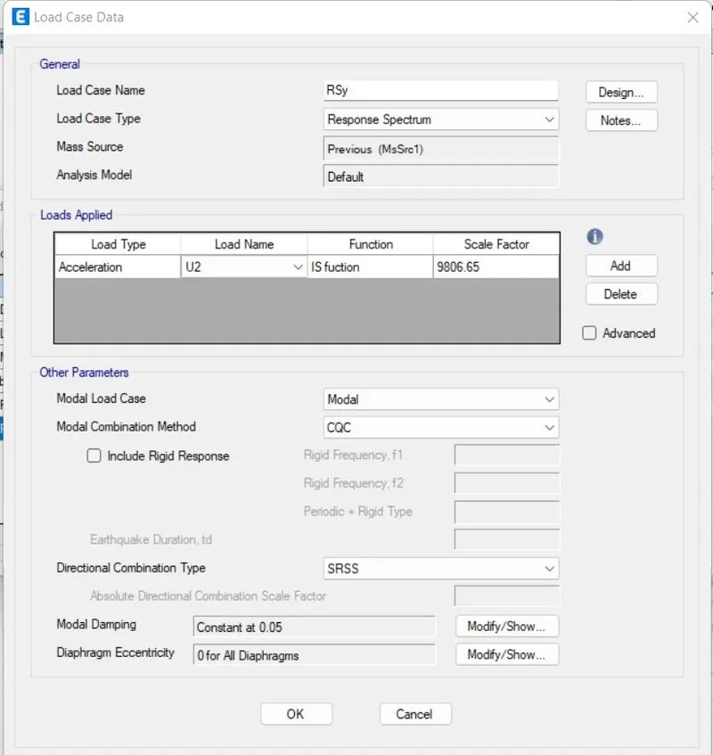
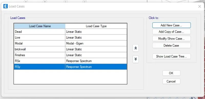
Step 19:Define-load cases-Add new load cases
Step 21:Add load combinations
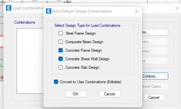
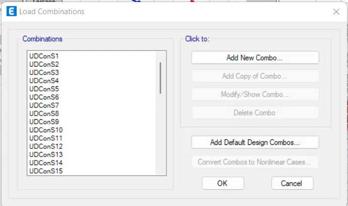
Step 20:Select ‘Run analysis’
RESULT
Display-Show tables
Structure output-model information
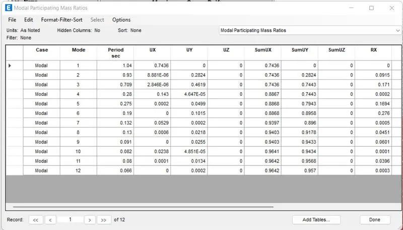
Select -modal participating mass ratios
Select -Display-Story response
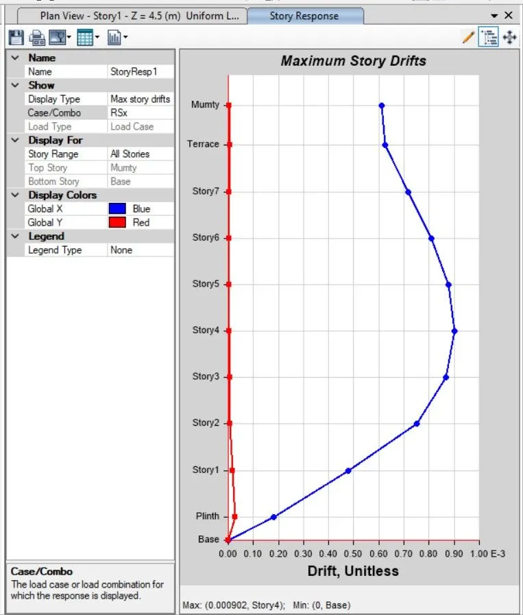
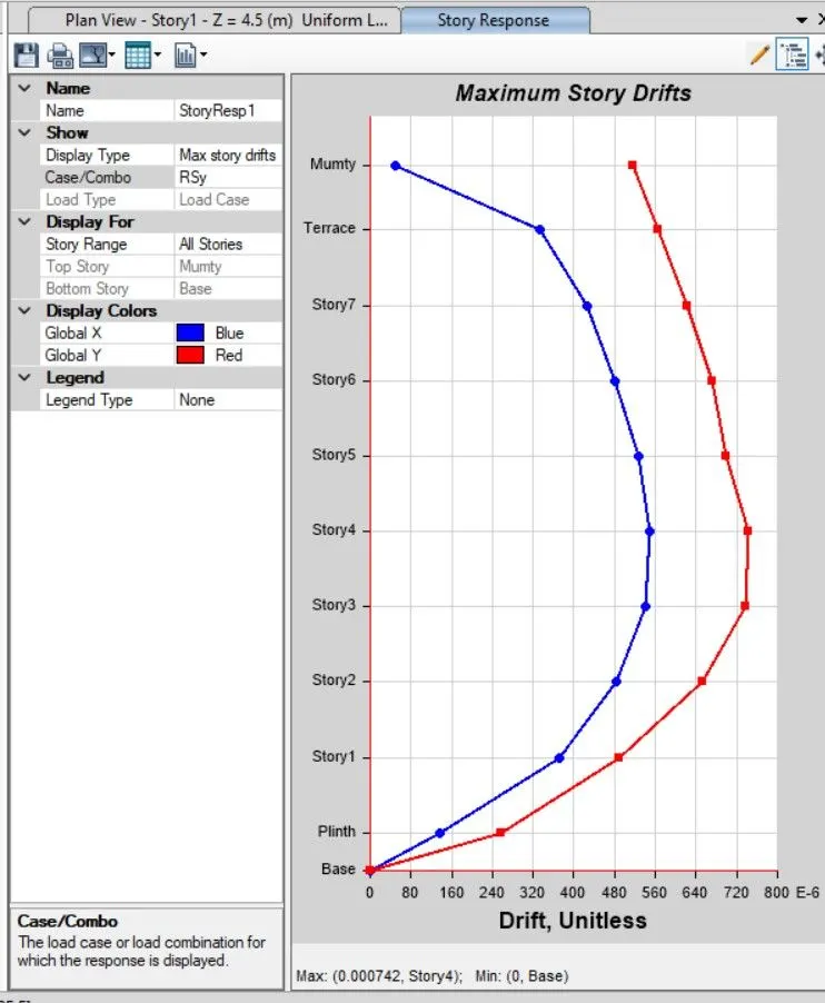
Modal mass participation for first 3 modes donates at least 65%- Achieved only for X-axis
Mode 1 and mode 2 differ by 10% - Achieved
Principal modes be greater than torsional mode -Achieved
Inter story drift limited to 0.004 -Achieved
Axial stress in column and shear wall - Achieved