Structural Modelling using Etabs 2018
The architectural drawings for a G+7 residential building in zone 5 has been provided. The floor plan is the same for all 7 floor levels. Possible column positions have also been provided. Conceptualize a framing plan layout and then model the building in Etabs. The following architectural drawings have been provided:
- Typical floor plan – The location and thickness of the brick walls and the use of the
space (for estimating live load) can be obtained from this plan - A building section through the staircase and lift core is provided
- Parking layout in the ground floor – the column/shear wall arrangement must not
obstruct entry/exit of vehicles.
The following loadings are to be taken into account: - Brickwall made of AAC blocks
- Finishes – floor tiles of 75 mm thickness
- Live loads as per IS 875 part 2
- Water tank of 20 KL above the staircase at Mumty level
- Lift Machine room at mumty level above lift core
The structural model must comply with provisions of IS 1893 and IS 13920.
Run a modal response spectrum analysis and check analysis results of the etabs model for inter-storey drift requirements, vertical & planar irregularities, minimum shear wall requirements,maximum axial load ratio for column and shear walls, effective moment of inertia for beams
and columns etc.
Aim:
To conceptualize a frame plan layout and then modeling in Etabs for the given architecture plan. The structure must comply with IS 1893 and IS 13920. Then check the analysis result in ETABS.
Introduction:
Data required for ETABS analysis
• Pinned Support, Base + 9 Story (Ground to terrace) + 1 Mumty
Assuming Column 450mm x 600mm, Beam 400mm x 500mm, Slab 150mm thick, Shear wall 300mm thick
• Live load 2.5 kN/m2, Floor finish 1.5 kN/m2, Wall load 5 kN/m, Water tank 20K
litre over mumty equivalent to 200 KN overall load.
Conceptual design considerations before analysis
• Re-entrant and cutout check & modification (Compromise)
• Vertical irregularity (soft story)
• Planar irregularity (Looks symmetrical)
• 2% shear wall area with respect to building area (8 m2)
• Stiffness modifier for Column, Beam & Shear wall (0.35 for beam, 0.7 for vertical)
Procedure:
First we need to create a new model from thr given Etabs mdoel. we need to open the Etabs first and then click on the new to create a new model.
Once you open the new model we can see new window for the grid and the story data.
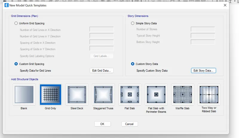
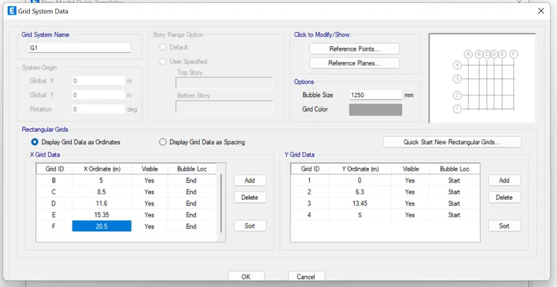
The first thing in the new model to add the grid data.
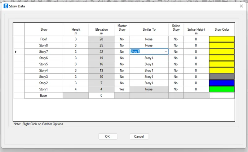
Now we give the story data with respect to the plan given.
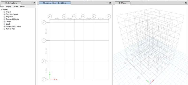
Now we can see the grid has been layout for us in ETABS.
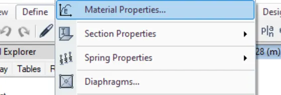
Now we need to define the material properties for that click on define in home tab and click on define.
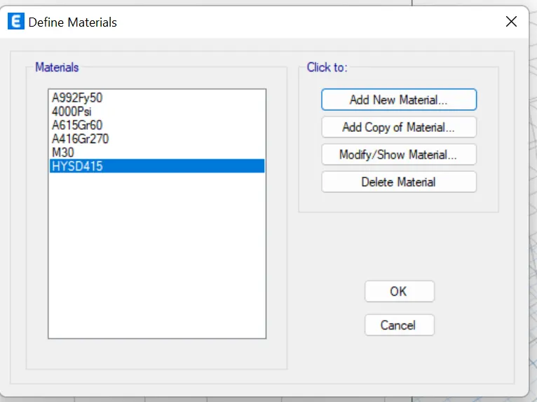
Now click on add material to add the new material.
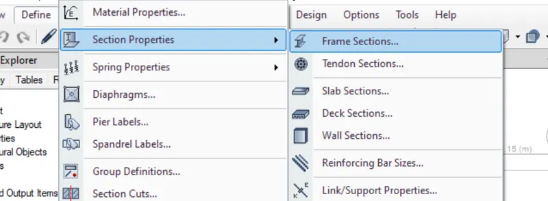
Now we need to define the beams click on define then section properties and then frames.
Now we cqan add the material data by giving the data.
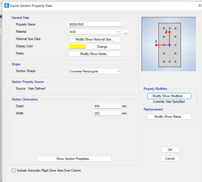
Now change the modyfier stiffness.
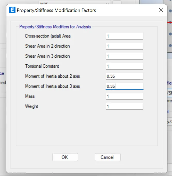
Now we can give the rebar data.
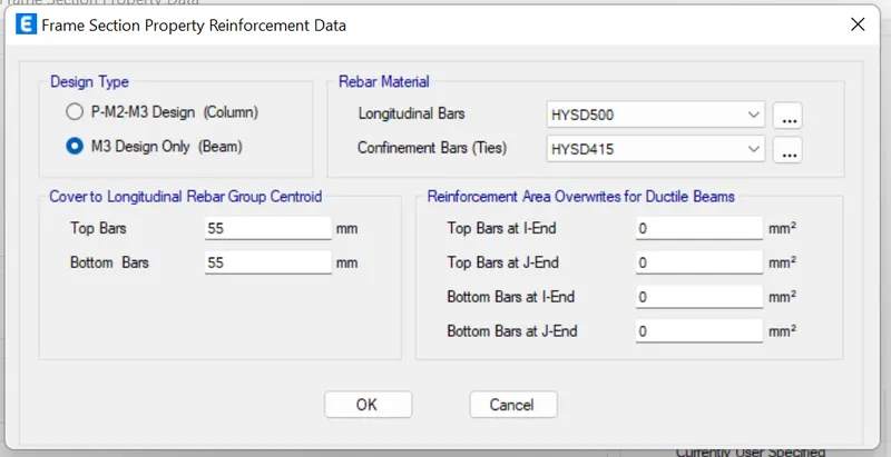
Now we got the data for the columan as the same way we add the data for the column.
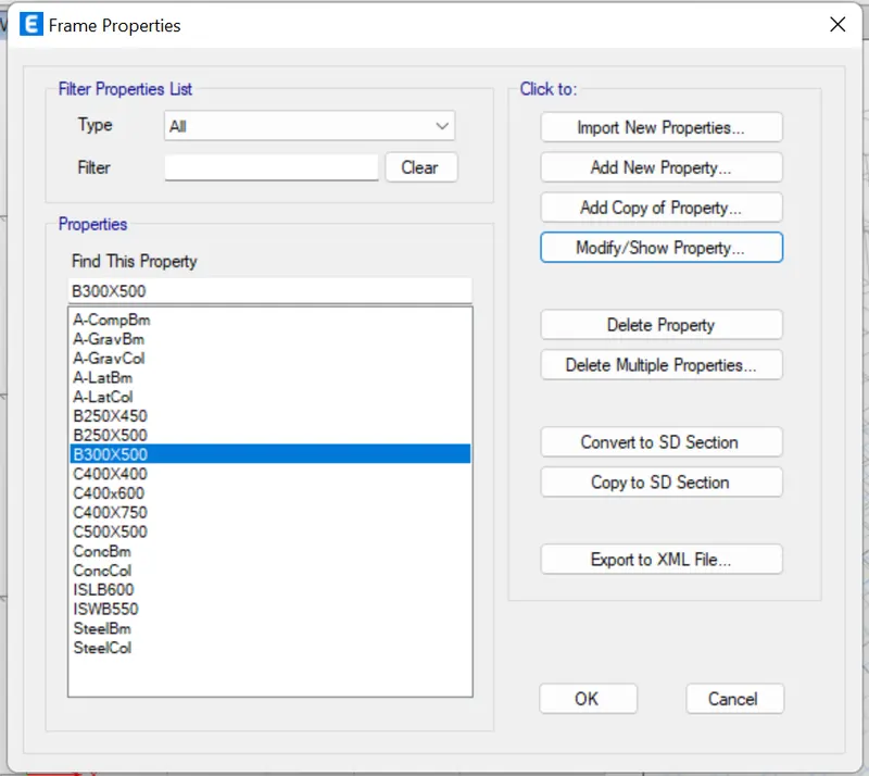
Now to add the material properties for the slab.
we need to click on the define then properties then click on slab then add the data.
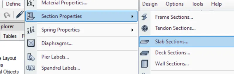
Now we need to click on the add new material properties.
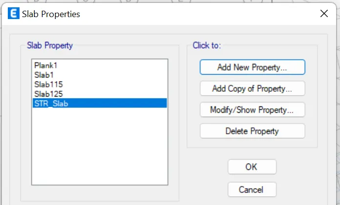
now we can give the material properties.
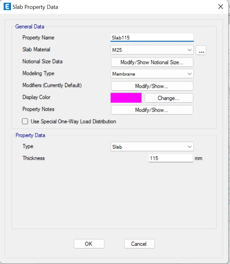
Now we need to add the material properties for the shear wall.
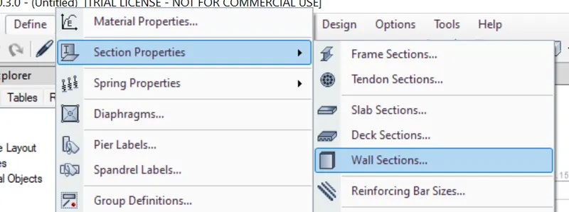
Now click on the define then click on the sectional properties and then click on the wall.
Now select wall 1 and then click on modify properties to see the details.
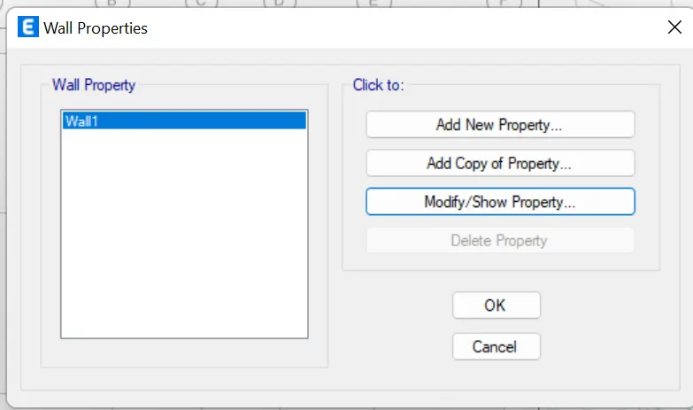
Now we can add the material data in the properties.
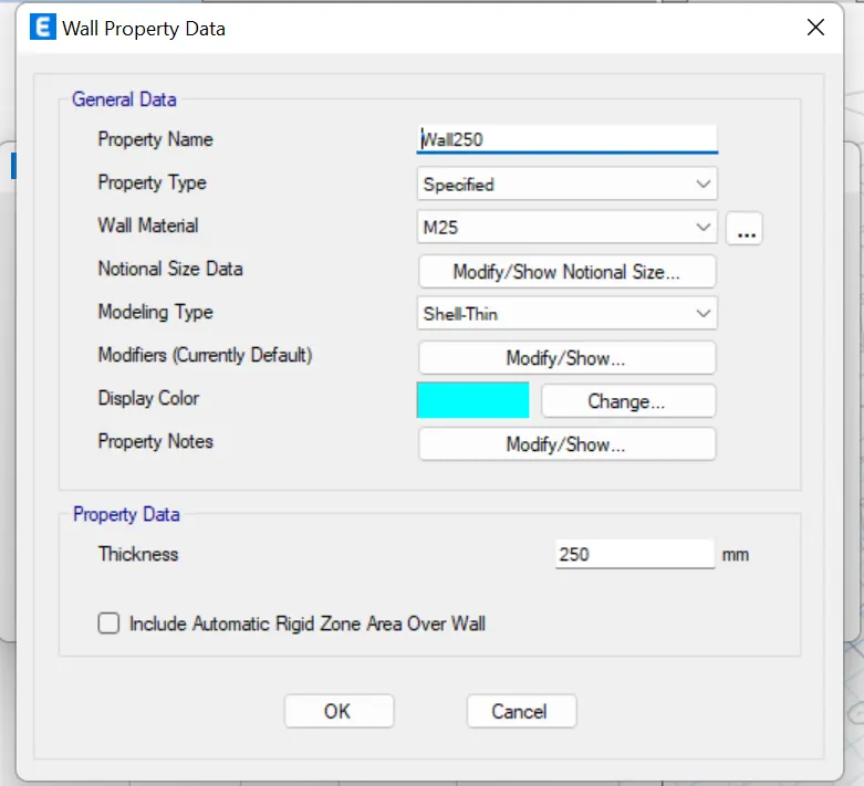
Now we have all the material properties. we can start adding the beam,columnas and floors and the shear wall.
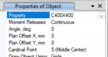
Now click on the quick add of the column then select the column property as required.
now once you select the quick draw we can now selecet the properties required in the properties browser in the left down of the screen.
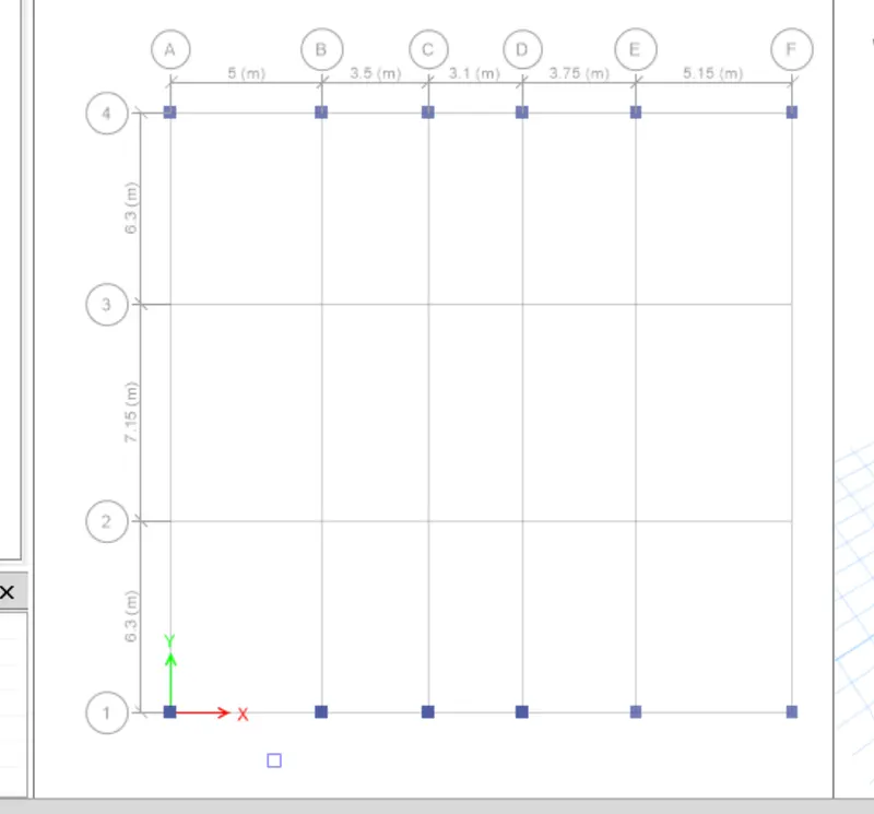
Then click on the grid intersection so that column will be added to the all stories.
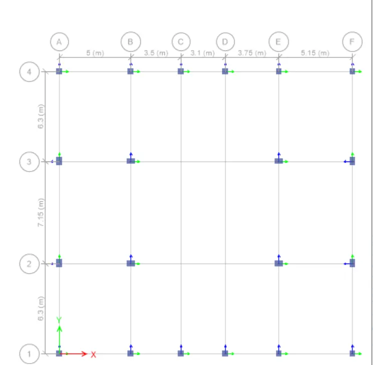
Now we will change the column properties and add them in the middle grids.
Now we can add the beams by using the quick draw beam option.
Then select the properties of the beam.
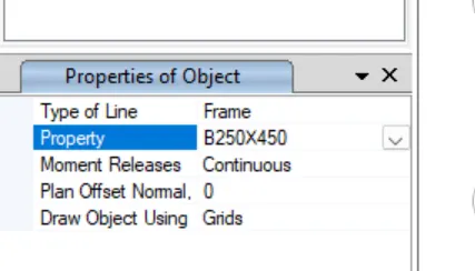
now click on the gris to add the beams.
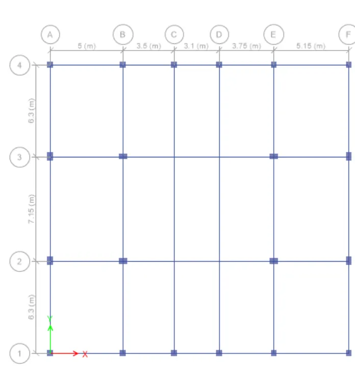
now to move the centeral beams as per the design.
we need to select the central beams and click ctrl+m
A small window will be poped up give the valuew in which direction you want it to be moved.
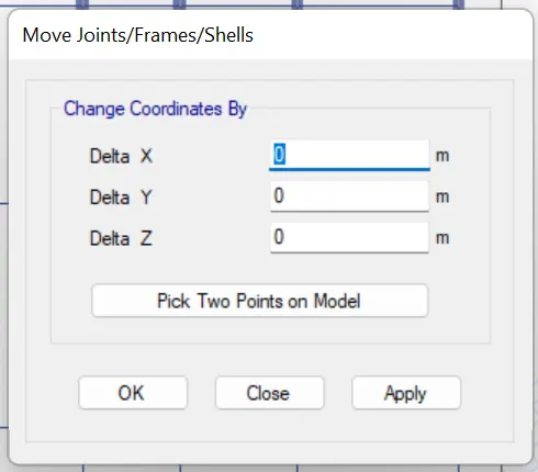
now we can see the moment in the frame.
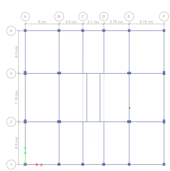
now we need to add the secondary beams in the plan.
we nee to click ctrl+r so that we can replicate the beams into secondary beams.
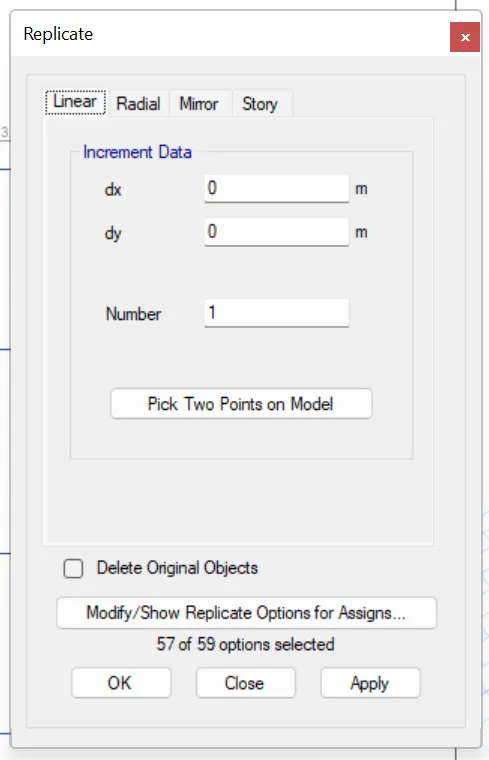
now give the values and press appliy and ok so that we can see the beam replicated.
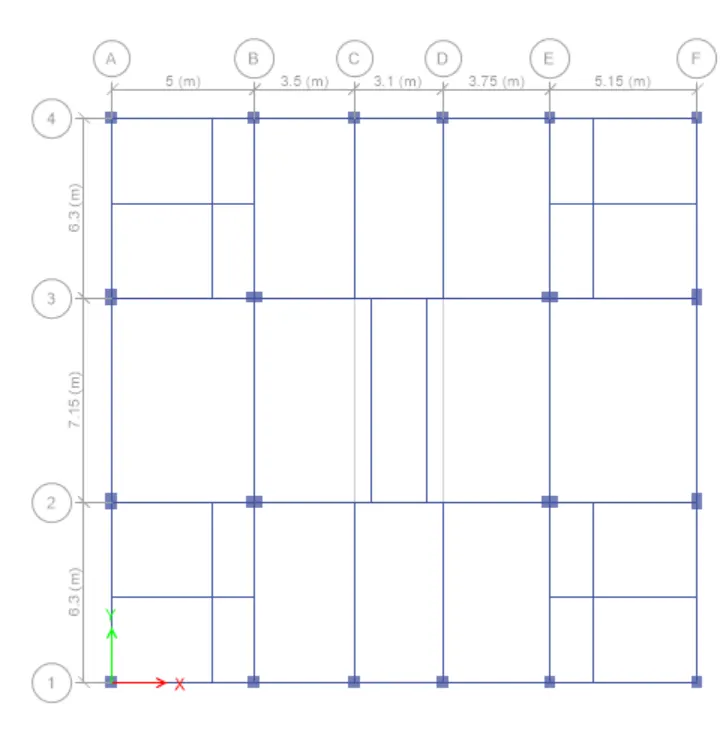
now to breaks the extra beams.
Frist select the beams and then click on the edit then edit frame and then click on the divide the frames.
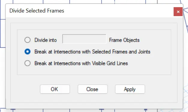
Now click on aplly and then ok.
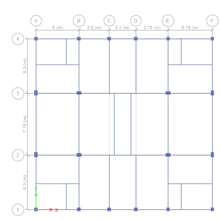
now we have all the intermediate frames.
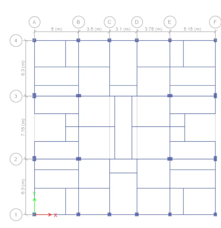
Now to add the shear walls fist we can add them in the corner for that we need to click on the
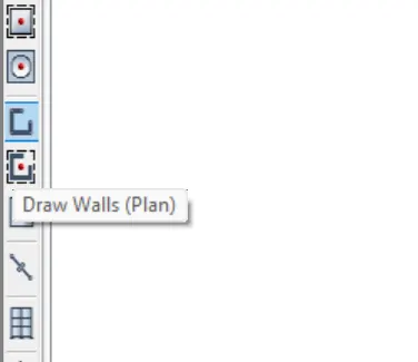
now click on draw plan in the left of the window screen.
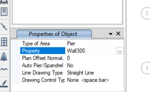
now select the wall properties in the properties browser.
now select the postiona and click on the screen.
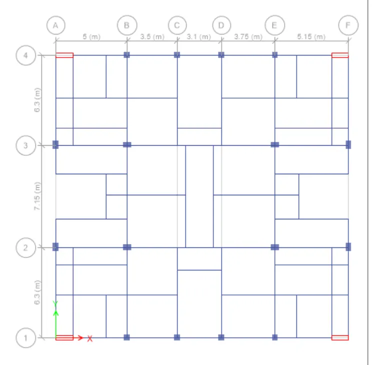
now we place the shear walls in the center as well.
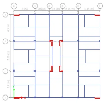
As we can see all the shear wall has been added to plan now.
we need to add the floor.
now select the quick draw slab in the left side of the screen.
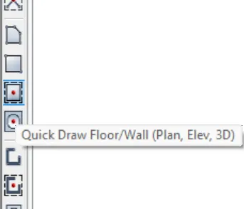
Now select the slab properties from the properties browser.
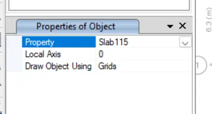
now select the frames i to add the slab and we can see the slab has been added.
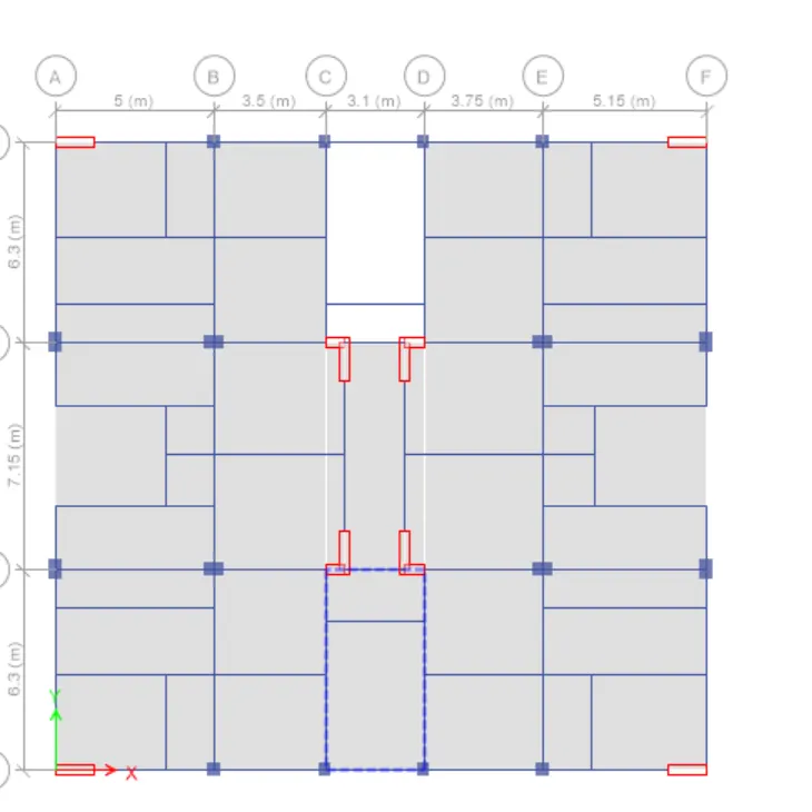
In the staircase point we use different type of slab.
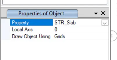
now add the slab again by clicking on it.
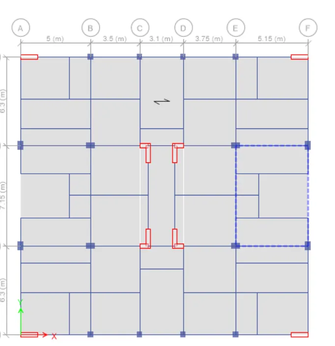
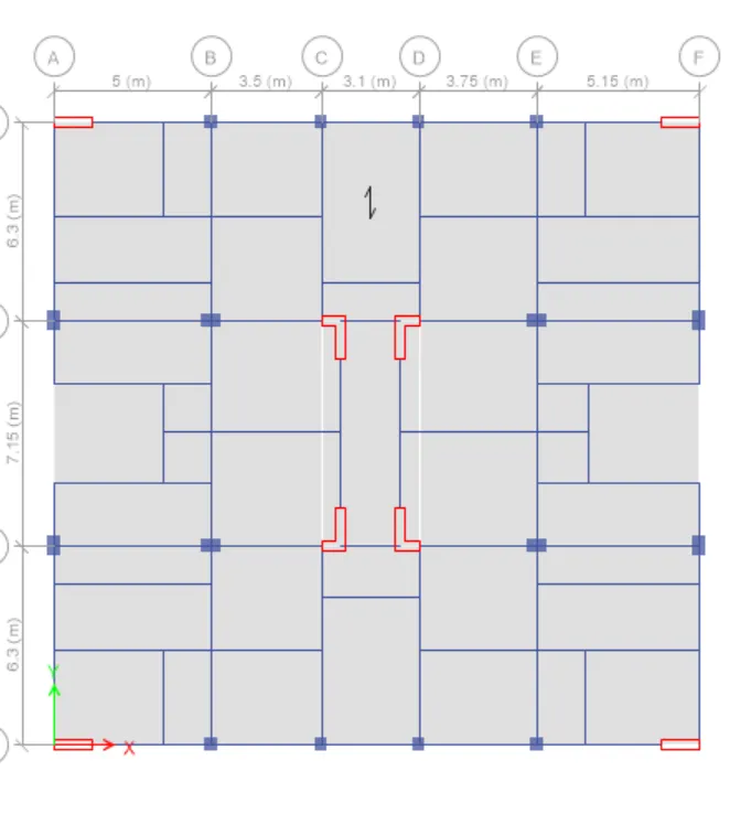
As of now we have the frames of the plan.
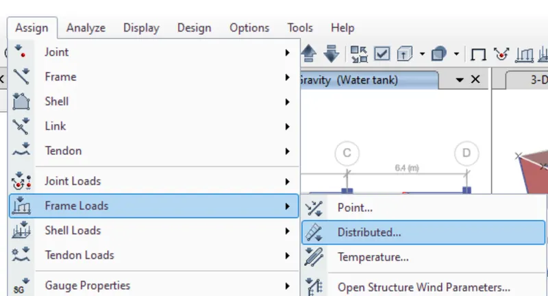
once the shear walls are placed now give the load. click on the assaign, frame load, distribute.
Now select the frame beams and the give the load values.
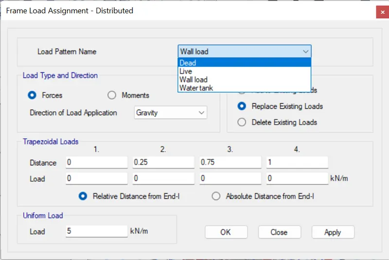
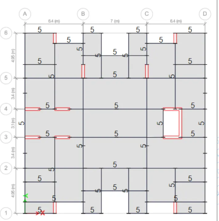
Then click on apply and then click on OK. we can see the load applied
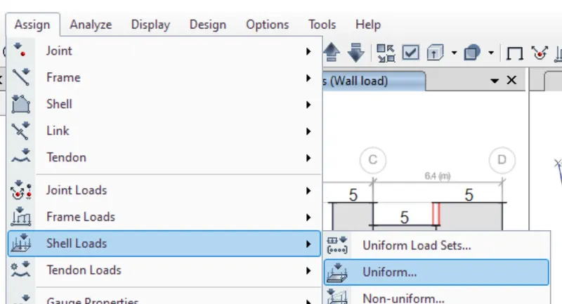
As the same way now we are going to apply the shell loads and thi is for the floor and the live loads.
click on the assaign then click on the shell loads then click on the uniform distribution.
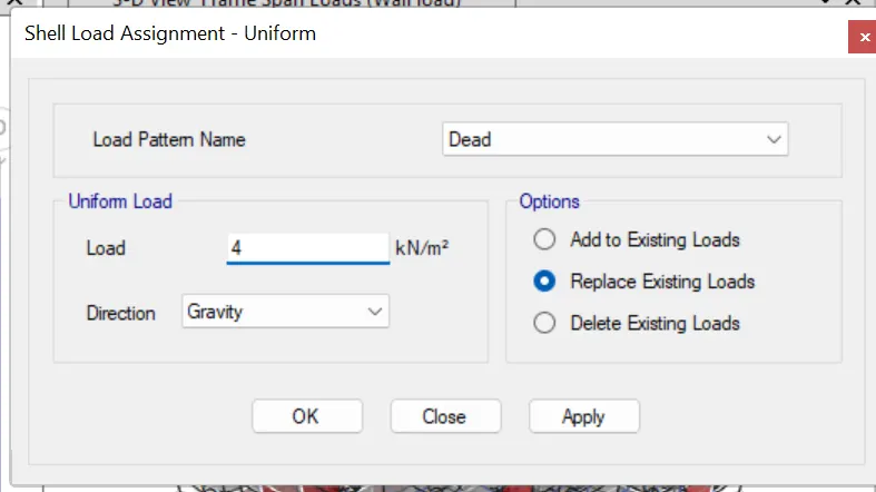
Now click and select the floor give the load amount and then click on the apply and ok.
now we add the wall load as well.Now we can see the floor load and the wall load.
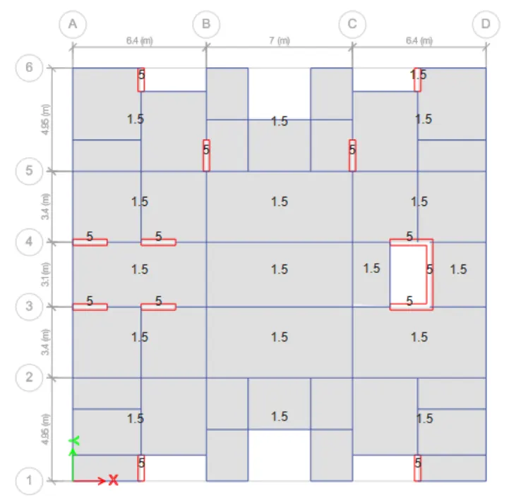
now we have all the loads in the design now we need to assaign a diaphrame to the structure.
Now click on assaign, shell, diaphrame.
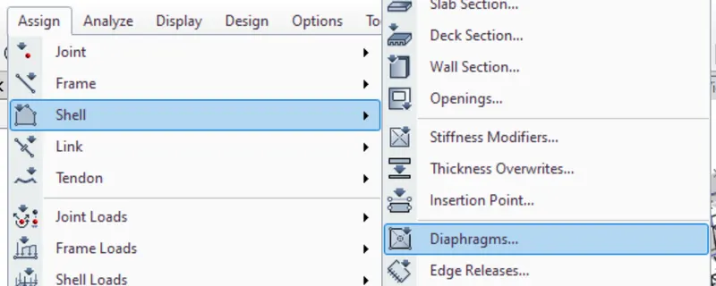
Now select the d1.
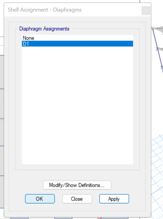
Now click on apply and then OK.
we can see the diaphrame has been assaigned to the model.
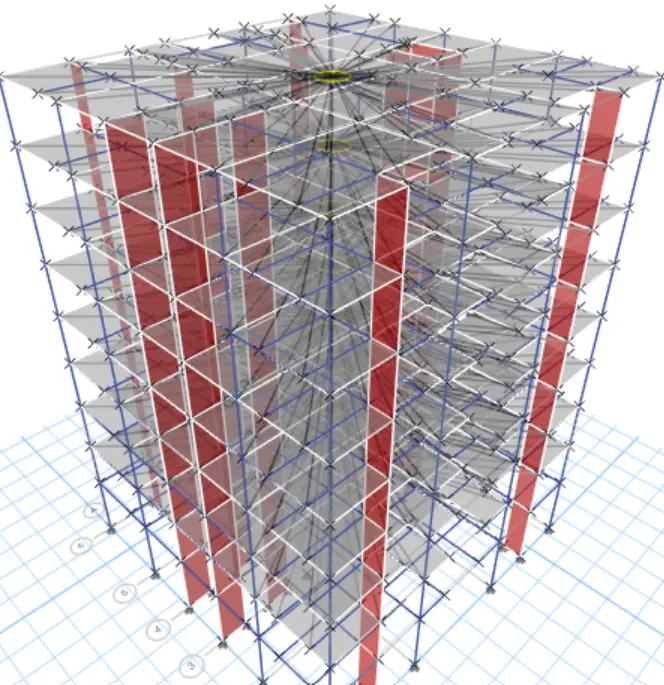
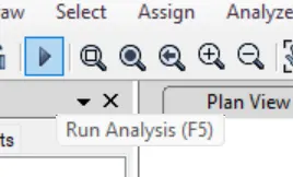
Now run the analysis to check the model.
To run the analysis click on the play button on top of the model.
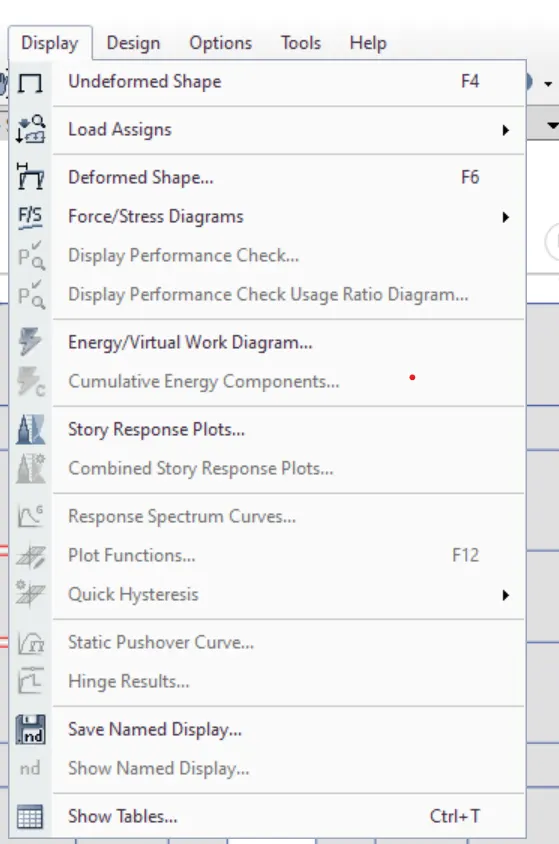
once analysis is donenoe we can check the model. To check the model click on the display and then show table
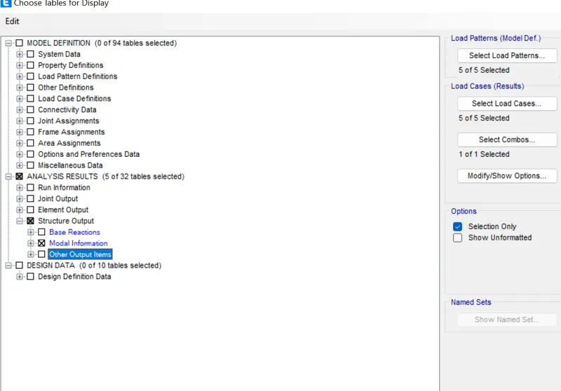
now click and select the table in which you want to see the information.
Checks after analysis:
Modal mass participation for first 3 modes dominates at least 65% (Achieved for X-axis only)
Mode-1 and Mode-2 differs by 10% (Achieved)
Principal modes be greater than Torsional mode (Achieved)
Inter story drift ratio limited to 0.004 (Achieved)
Axial stress in Column and Shear wall (Achieved)
Base shear share between shear wall & Columns (Not dual system)