Structural Modelling using Etabs 2018
Solution:
Aim:
- To conceptualize a framing plan layout and then model the given G+7 building situated in zone 5 in Etabs.
- To develop the structural model that comply with provisions of IS 1893 and IS 13920.
- To run the modal response spectrum analysis and to check analysis results of the etabs model for inter-storey drift requirements, vertical & planar irregularities, minimum shear wall requirements,maximum axial load ratio for column and shear walls, effective moment of inertia for beams
and columns etc.
Procedure:
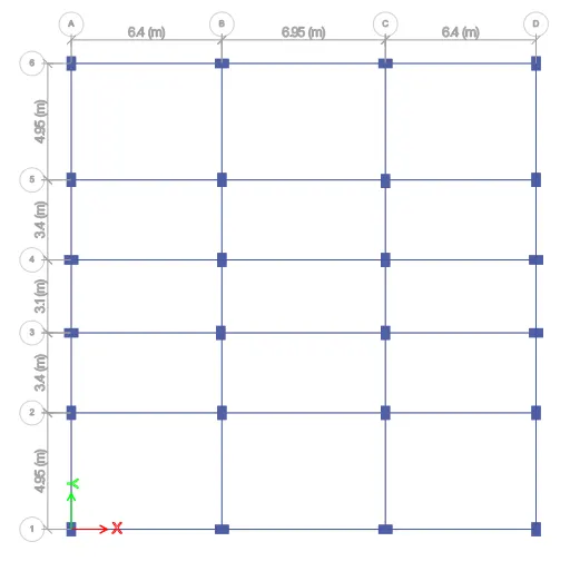
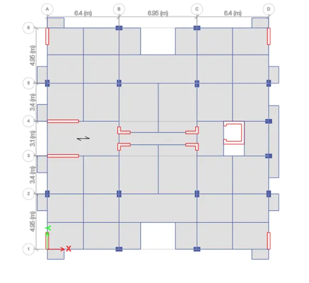
- Initially open the given AutoCAD file and locate the positions of columns beams and possible loaction of shear wall.
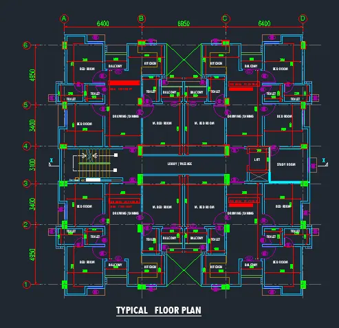
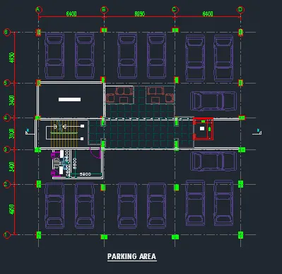
- Now, open the Etabs file and provide the grids and storey information as required and given.
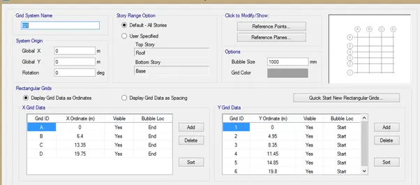
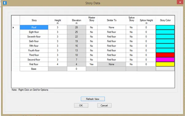
- Next we need to define the material property for concrete and reinforcement.
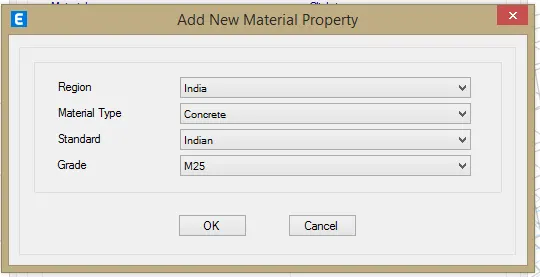
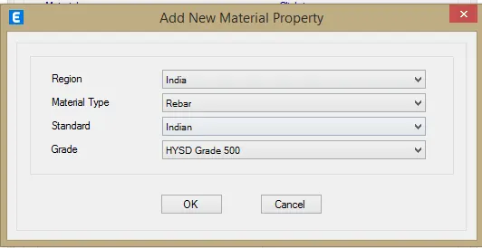
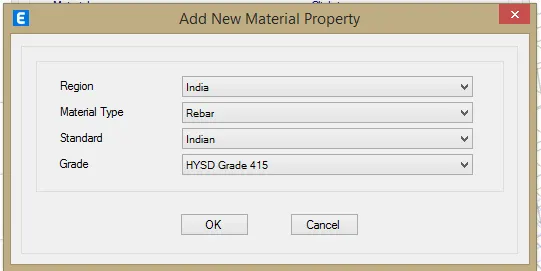
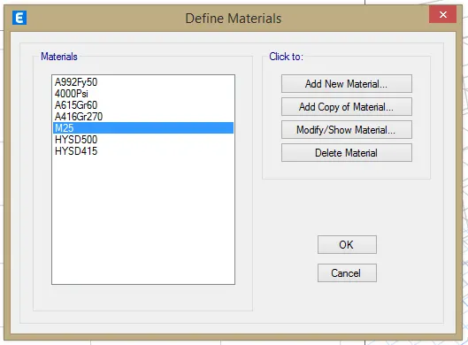
- Then, define the section property for column, beam and wall.
- For this, go to define tab -> section property --> frame section --> Beam 300X450mm and column 400X600mm.
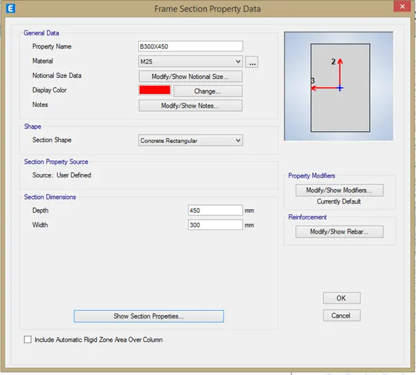
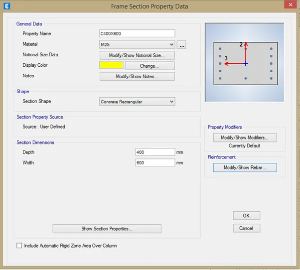
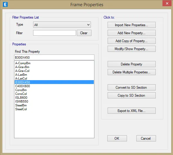
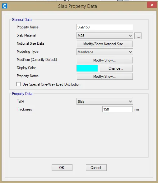
- Now, define the slab properties. Define --> section properties --> slab sections --> Slab150 and slab 125.
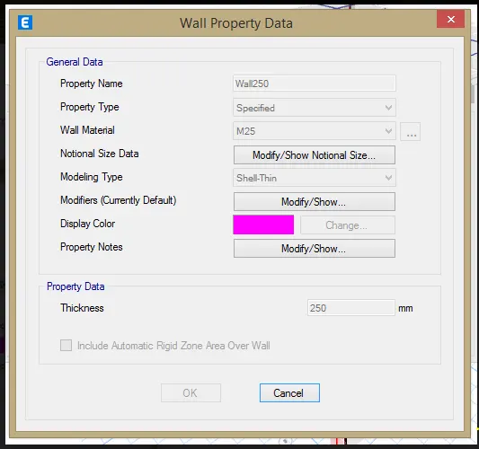
- Next thing that we need to define is the wall properties.
- Go to Define --> section properties --> wall sections --> wall250.
- Hence we have now defined the material as well as section properties, so now we need to place the components in the suitable positions.
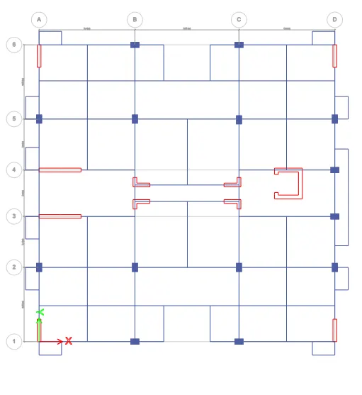
- So, for this go to quick draw columns and place the columns at suitable positions(C400x600).
- Similarly place the beams(B300x450) and shear walls at suitable locations without obstructing the parking area.
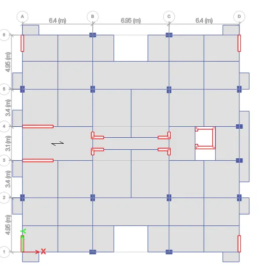
- After this we need to place the slabs , for staircase slab we use slab150 and for remaining area we use slab125.
- Now make the staircase slab as one way slab.
- Next, we need to provide loads before carrying out the analysis.
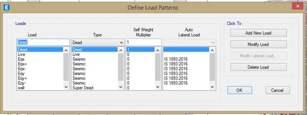
- Define --> load patterns.(Include wall and load floor finishes as super dead loads)
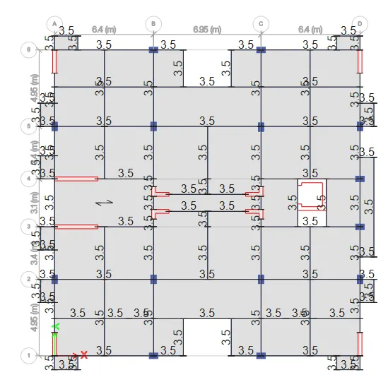
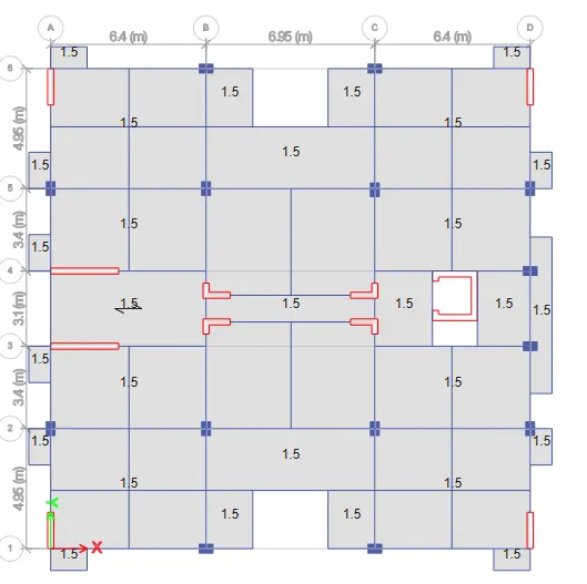
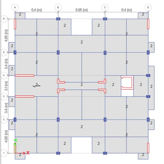
- After defining assign the load cases.
- Brickwall load is asssigned as 3.5kN/m.
- Floor finishes - 1.5 `(kN)/m^2`
- Live load - 2 `(kN)/m^2` and 5 `(kN)/m^2`for terrace as it contains mumty and lift unit.
- Also provide the liveload reduction factor as per IS875 part II.Design --> Live load reduction factor.
- Next we need to define the mass source.
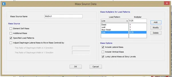
- After defining mass source, next we have to define the modal case. Keep the max no. of modes as 20.
- Next we need to define the response spectrum function. Define--> Response spectrum --> Func. name: RS function -->ok
- Then go to load case --> add new case --> RSx (U1)--> load case type - Response spectrum-->Then fill load applied details.similarly add another load case as RSy (U2).
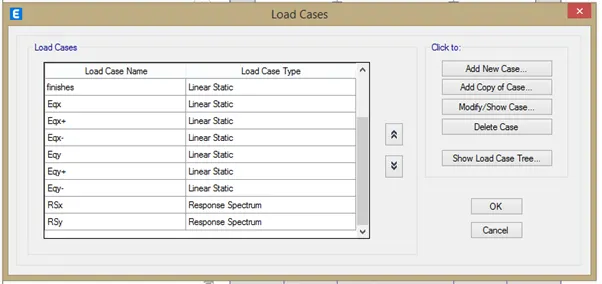
- Now, Assign --> shell --> diaphragms --> D1 --> Apply.
- Then assign pier labels.
- Now, go to define --> load combinations --> add default load combinations --> choose concrete frame design and concrete shear wall design --> convert to user combination.
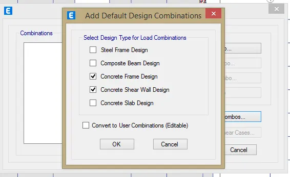
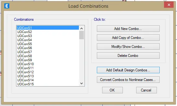
- All the inputs have been provided, now we can check the model. Analyze --> check modal.
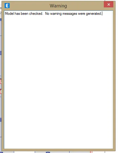
- Now, we can run the analysis.
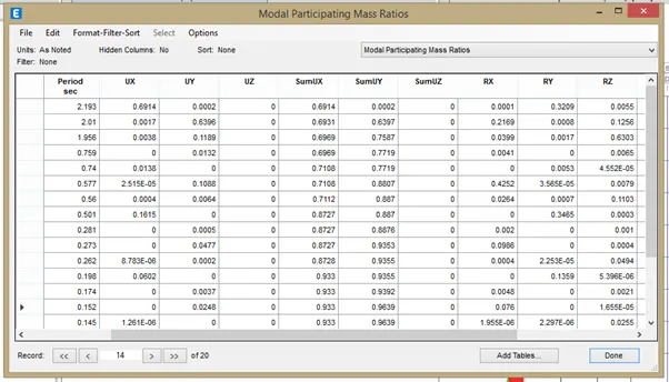
- Once, the analysis is over, go to display --> show tables -->analysis result --> structure output --> modal information --> modal mass participating ratio.
- Mode 1 - 69.14% ; Mode 2 - 63.96% ; Mode 3 - 63.03%
- Hence, the mass participation of translational mode (first two fundamental modes) is greater than torsional mode(third mode).
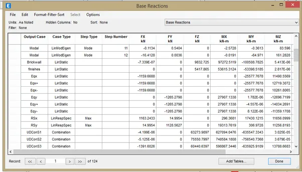
- Now, in display choose base reactions. Go to display --> show tables -->analysis result --> structure output --> base reactions.
- Eqx obtained is 1159.66kN and RSx = 1163.24kN. Hence, the scale factor = 1159.66/1163.24=0.9969.
- Similarly, Eqy = 1265.27kN anf RSy = 1128.56kN. Scale factor = 1265.271128.56=1.12.
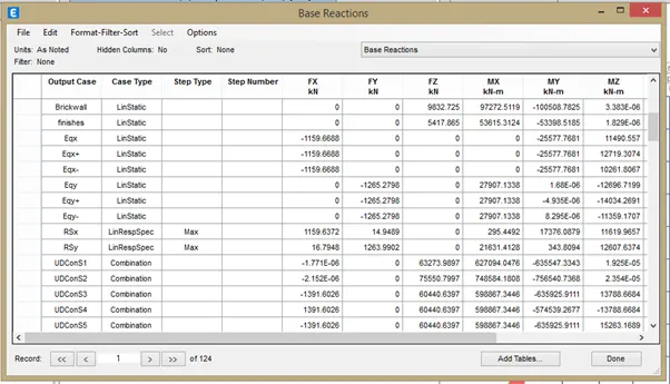
- So, now, keep these values as scale factor.
- Now, both Eq and RS values are made same using the scale factor hence, the Eqx and Eqy can be removed from the load case and combinations.
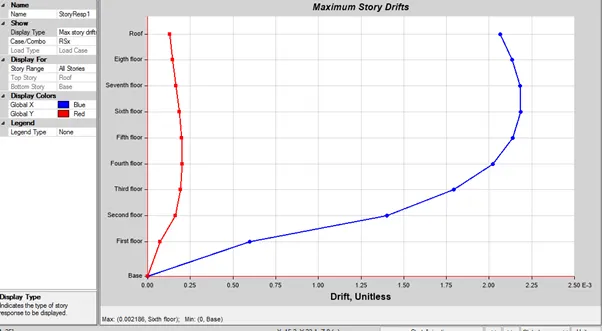
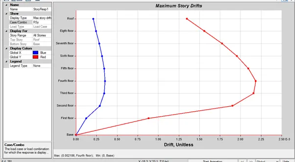
- Now, we need to check the interstory drift. For this display --> story reponse plot -->maximum stry drift
- Here, for both RSx and RSy the max story drift is within 0.004 as given in IS1893-2016
- Now, the axial force diagram is given by display --> force/stress diagram --> frame/pier/spandrel/link forces.
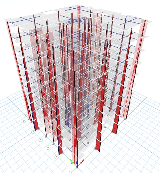
- Hence the completed modal of the G+7 building is as given below:
Result:
- The structural modal of the G+7 building has been developed that complies with IS1896 and IS13920.
- After framing the layout, analysis has been carried out.
- Necessary checks have been carried out and also verified the values with the code.