Structural dynamics
Q No.1:-
Ans:-
Static Analysis:-
- In static analysis we analysis static load means a force that has constant size, position and direction on or within a structure.
- Study of static load help determine the maximum allowable load to be applied to the structure.
- In static analysis we use equation of equilibrium for a structure under static loading is:f=ku, where u is the displacement.
- Load is not variable with time and neglected due to slow applying of load.
- Motion of the structure can be disregarded.
- Static analysis doesn't considered inertia force along with static force.
- The displacement obtained by static analysis is more.
- Static forces does not change in size, position or in direction.
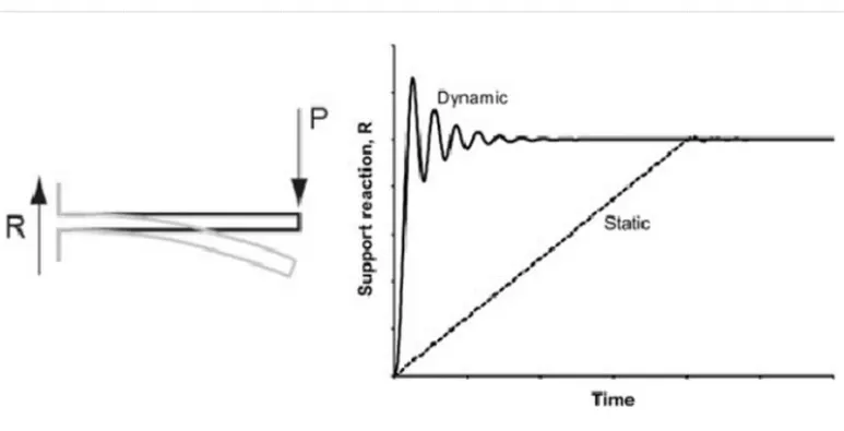
Dynamic Analysis:-
- In Dynamic analysis we analysis dynamic load means a force on a structure that change size, position or direction.
- Study of dynamic load help determine the stresses at the different points of the structure due to changing conditions over time.
- In dynamic analysis two additional force must be accounted.
- Inertial Force -F=m*a(where "m" is mass, "a" is acceleration)
- Damping Force -F=c*v(where "c" is Damping force coefficient, "V" is velocity)
- Unlike static loading's which remain constant or act in such a manner so that there is no substantial variation in structural response with time, dynamic loading's vary substantially with time, thus the structural response needs to be calculated at every time instant.
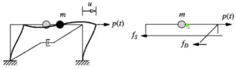
- The equation of equilibrium for a structure under dynamic loadingis:mu¨(t)+cu˙(t)+ku(t)=p(t). Where, u¨ is the acceleration (the double derivative of the displacement) and u˙ is the velocity (the single derivative of the displacement).
- Load is variable with time due to fast applying of load and vibrations.
- Motion cannot be disregarded.
- Dynamic analysis considered inertia force along with dynamic force.
- The displacement obtained by dynamic analysis are less.
- Whereas in dynamic forces changes in either size, position or in direction.
Structural analysis deals with the change in behavior of a physical member under the applied loads. The nature of response of the system is completely dependent on the way the load is applied to the component. If the load applied slowly, the inertial effect defined on the basis of Newton's first law of motion will be neglected and this is called as a static analysis. In static analysis, a single output value of solution is obtained for the system in the form of displacement, reaction forces etc. In a broader sense, static forces are considered as constant loads acting on the structure. A simple example of static load is a block of iron laying on a surface, a stationary truck etc.
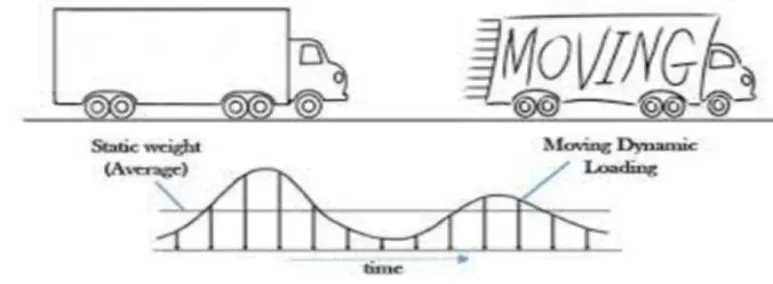
Representation of static and dynamic loads
Dynamic means time varying, and as the name suggests, the applied loads vary with time and thus induce time varying responses (displacements, velocities, accelerations, reaction forces, stresses etc). One of the most notable difference in dynamic analysis is the explicit consideration of inertial forces developed in the structure when it is excited by the time varying loads. Due to its time-varying characteristics, dynamic analysis is more realistic in nature to the actual occurring event but it also makes the modelling more computationally demanding. Some of the examples of dynamic loads are hammer striking on iron block, a moving truck on a bride etc.
Q NO.2:-
Ans:-
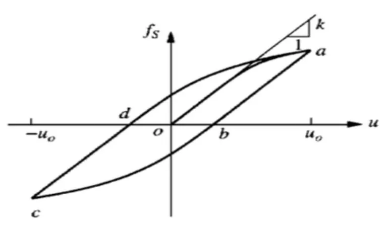
Figure:2.1
Force-Displacement graph for Elastic behavior.
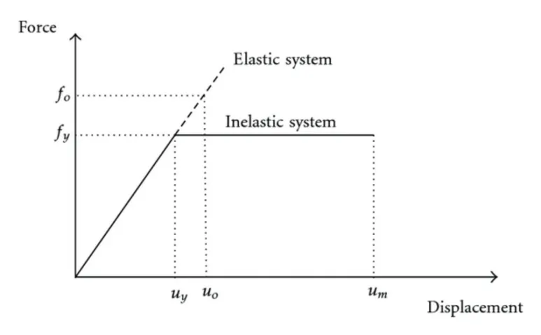
Figure:2.2
- Elasticity, ability of a deformed material body to return to its original shape and size when the force causing the deformation are removed.
- For a linear elastic system the relationship between the lateral force fs and resulting deformation u is linear that is, fs=ku; where k is the lateral stiffness of the system; its unit are force/length.
- In linear deformation k is constant.
- This deformation would be linear at similar displacement. But would become non linear at larger deformations.
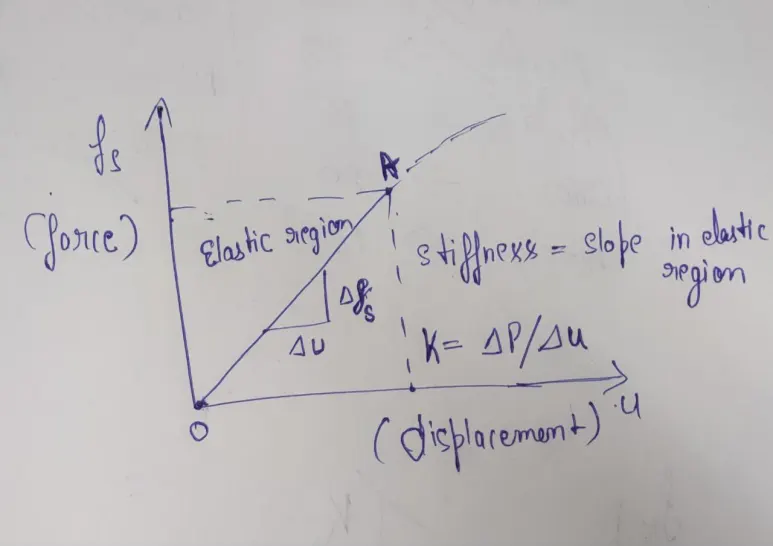
Figure:2.3
Force-Displacement Graph for Inelastic behavior.
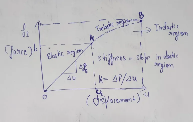
Figure:2.4
- In region AB is inelastic region in that region we apply the load to the substance will deform permanently "it will not regain it's original shape".
- Inelastic behavior is the property of the material when the material can't retain it's previous shape after a certain deformation. In the aforementioned graph inelastic behavior has been shown in the upper shape of the curve upto point "a". Figure 2.1.
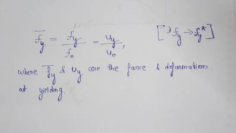
Figure:2.5
If the normalized yield strength of a system is less than unity, the system will yield and deform into the inelastic range e.g., fy0.5 implies that the yield strength of the system is one half of the minimum strength required for the system to remain elastic during the ground Motion.
Force-Displacement Graph for Plastic Behavior:
- Plastic Deformation: The material does not return to its original shape when the force is removed.
- For stresses beyond the elastic limit, a material exhibits plastic behavior.
- This means the material deforms irreversibly and does not return to its original shape and size, even when the load is removed.
- When stress is gradually increased beyond the elastic limit, the material undergoes plastic deformation.
- Plastic behavior occurs when the material completely lost it's ductility. In the above mentioned graph plastic behavior occurs during unloading after point "a" Figure:2.1.
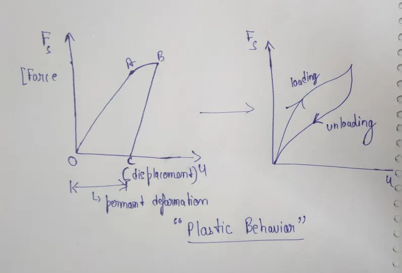
Figure:2.6
Force-Displacement Graph for Non-Linear Inelastic behavior:
- Force displacement relationship becomes non-linear and inelastic at large deformations.
- Force fs corresponding to deformation is not single valued and depends on history of deformations and whether deformations is increasing or decreasing. Thus resisting force can be expressed as fs=fs(u,v).
Ans:-
The single degree of freedom system can be viewed as a combination of 3 pure independent system.
- The stiffness component
- The damping component
- The mass component
- The term stiffness is used in earthquake engineering to designate how well a building will endure large lateral displacements imposed by ground shaking.
- Stiffness is a measure of how much force is required to displace abuilding by a certain amount. The frame without damping or mass.
- The external force fs on the stiffness component is related to displacement u by fs=ku.
- If the system is linearly elastic.
- Damping is the dissipation of vibratory energy in solid mediums and structures over time and distance.
- Similar to the absorption of sound in air, damping occurs whenever there is any type of friction that diminishes movement and disperses the energy.
- The frame with its damping property but no stiffness or mass.
- The external force on the damping component is related to velocity by Fd=cv
- The vertical irregularities in structures are stiffness irregularity, Mass irregular, Vertical geometric irregularity, Discontinuity in capacity. A. Centre of Mass.
- The center of mass is a position defined as the average position of all the parts of the system, weighted according to their masses.
- The roof mass without the stiffness or damping of the frame.
- The external force f1 on the mass component is related to acceleration by fi=mu".
- mu¨+ fd + fs = p(t) that is mu¨ + cu˙ + ku = p(t)
Q No.4
Ans:-
Natural period:- The time taken for undamped system to complete one cycle of free vibration is called as the natural period of vibration and it is denoted by the formula Tn = 2π/ωn and the unit is seconds.
Natural frequency:- The natural frequency is defined as the number of cycles i.e. one full cycle of free vibration completed in one second. It is denoted in radians/sec.
The relation between and natural period and natural frequency is that frequency is inversely propotional to the period of vibration.
fn=1/Tn.
Q NO.5.
Ans:-
Response spectrum: It is a concept of characterizing the ground motionn and their effects on structures of different time period Tn. A plot of the peak value of a response activity (u,v,a) as a funtion of natural vibration period Tn of the system is called the repsonse spectra. The peak response of all linear single degree of freedom systems can be computed by response spectra plot. Three types of plot are generally plotted with u and Tn as deformation response spectra and a similar plot is done with u* as relative velocity specgtrum and with u** as accelerationn response spectrum. Each pot is done with fixed damping ratio and several such plots with different damping ratio are created for the range of damping values encountered in the structures.
Deformation response spectrum:
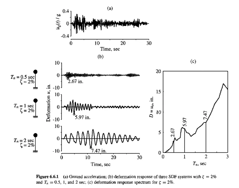
The above image contains the plot with deformation with respect to time. The 1st plot (a) represents the ground acceleration recorded during a earthquake. The second plot (b) represents the plots of deformation response of three independent SDF systems. In each plots of b has been done with fixed damping ratio as 2% and variation in natural time period as 0.5s, 1s, 2s and the corresponding deformations are obtained with respect to time. Finally a plot of recorded dimensions and Tn is done to record the peak responses. So based on the time period of vibration the deformation of the system can be obtained which can be multiplied with stiffness to obtained which can be multiplied with stiffness to obtain equivalent static force which can be further used for the analysis of the structure.
Pseudo acceleration response spectrum: Pseudo acceleration for an single degree of freedom system with natural frequency is related to its peak deformation D=U0, due to earthquake ground motion:A = (ωn^2) * D = ((2π/Tn)^2) * D. The here represents relative deformation and not total deformation hence, the acceleration obtained is relative so it is called as pseudo acceleration. The quantity A has units of acceleration and it is related with base shear Vbo.Vbo = fso = mA (or) Vbo = (A/g)*ω. In this formula A/g is base shear coefficient which is acceleration divided by gravitational force. So multiplying this with total mass of the structure provides total base shear or equivalent static force which can be used for analysis of the structure.
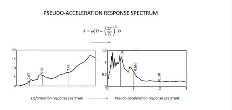
The above image represents the graphical difference between deformation spectra and pseudo acceleration spectra. Pseudo-acceleration can be calculated by multiplying deformation with natural circular frequency of vibration at any instant of time.