Creating Architectural and Structural model with 3D rendering using REVIT
Q No.1 Ans:- From the given options of type of structure for designing I have selected the Office Building.
Q No.2 Ans:-
The geographical and location details for my project modelling, based on assumptions of multi-unit residential apartment.
Selected identify the modelling requirements from NBC.
- As above mentioned by the building comes under the residential category and it can be situated in center of the city.
- The project is located in the highway nearest.
- The road width of this project is 60 Feet.
- The height, area limitation and safety measure are followed by the NBC 2023.
- The height of the project is 42.
- This project height in meter is 12.8m and the road width is 18.2m the height of the building should not exceed 1.5 times the width of the road.
- In case of building height is not exceed, so it is suitable for construction.
Q No.3 Ans:-
AIM:-
To using the structural model, include the following components based on the type of structure like wall, windows doors foundations, beams etc.
PROCEDURE:-
Step -I
- Open Revit software and create a new structural and architectural template and save them.
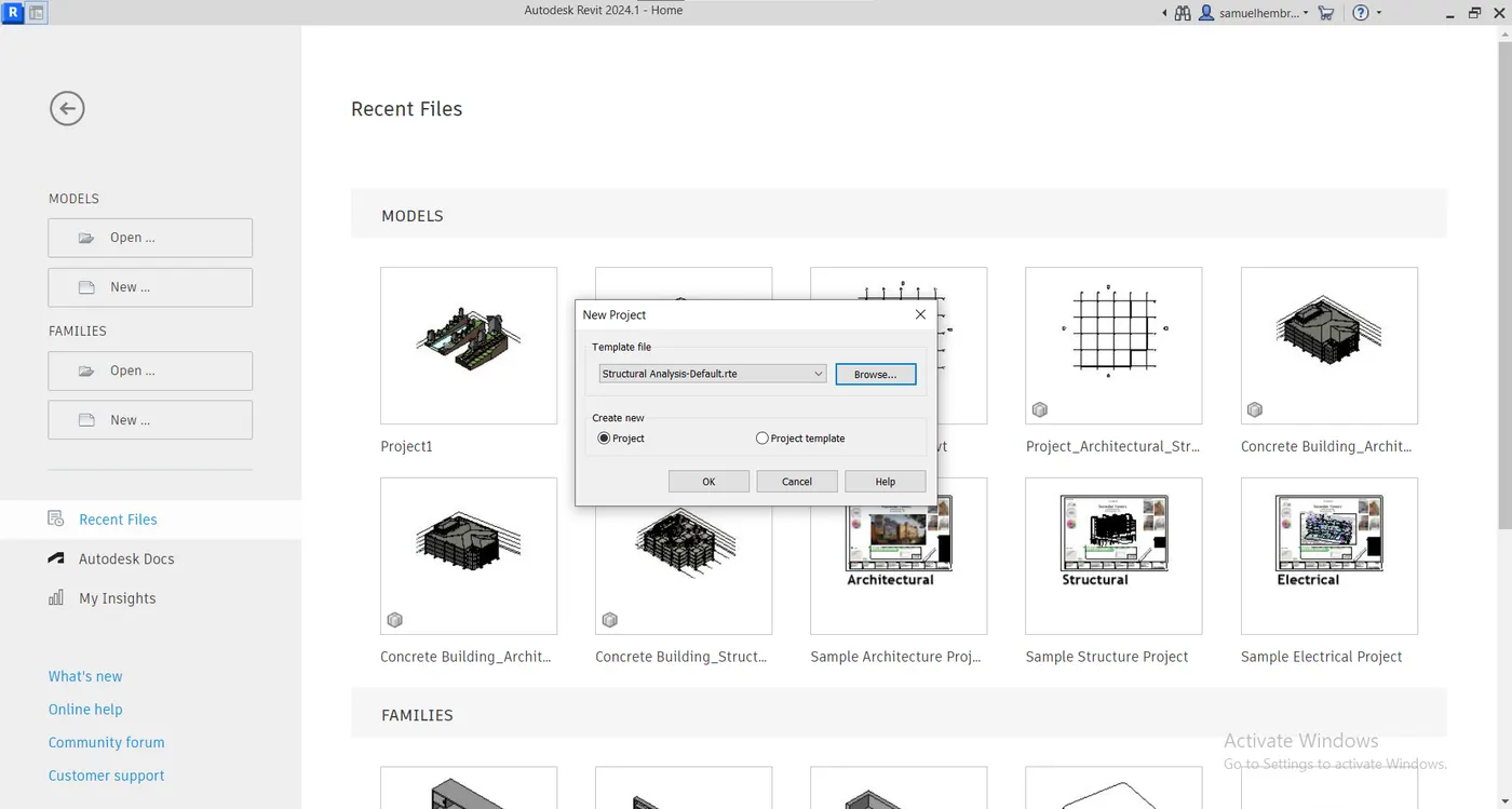
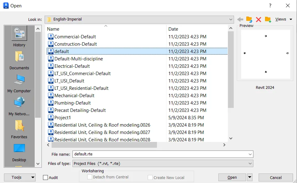
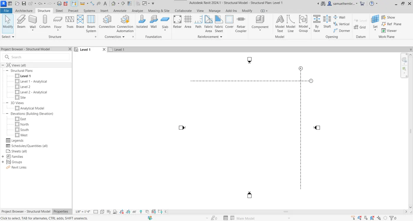
Step -II
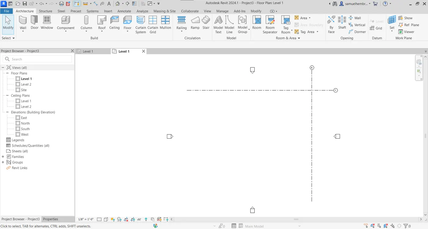
- Go to structural template and architectural template draw one horizontal and one vertical grid.
- Provide numeric name to horizontal grids and alpha numeric name to vertical grids.
- Go to Structure -> Datum -> Grid.
- Do the same for the Architectural template.
- Go to Architecture -> Datum -> Grid.
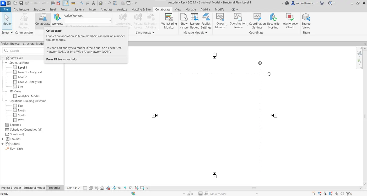
Step -III (For collaboration and Synchronization in Architectural Model)
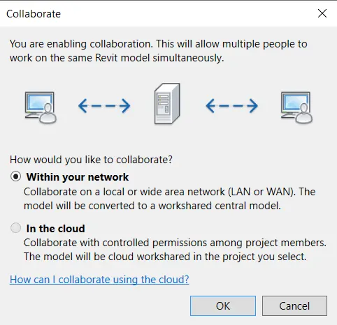
- Go to Collaborate -> Manage Collaboration -> Collaborate.
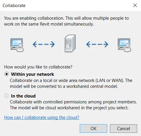
- The collaborate tab will open and press "OK" with "within your network" selected and save the project.
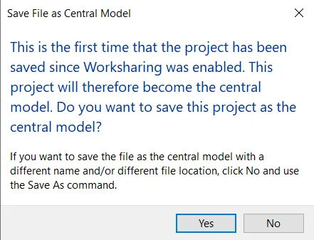
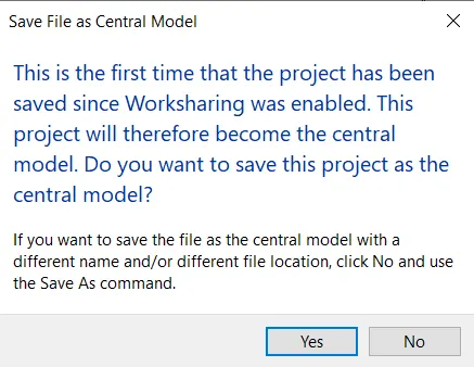
- Save the file as a Central Model.
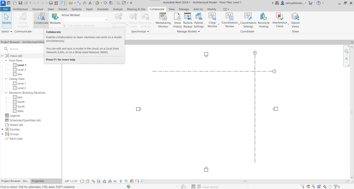
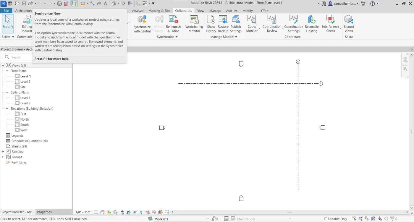
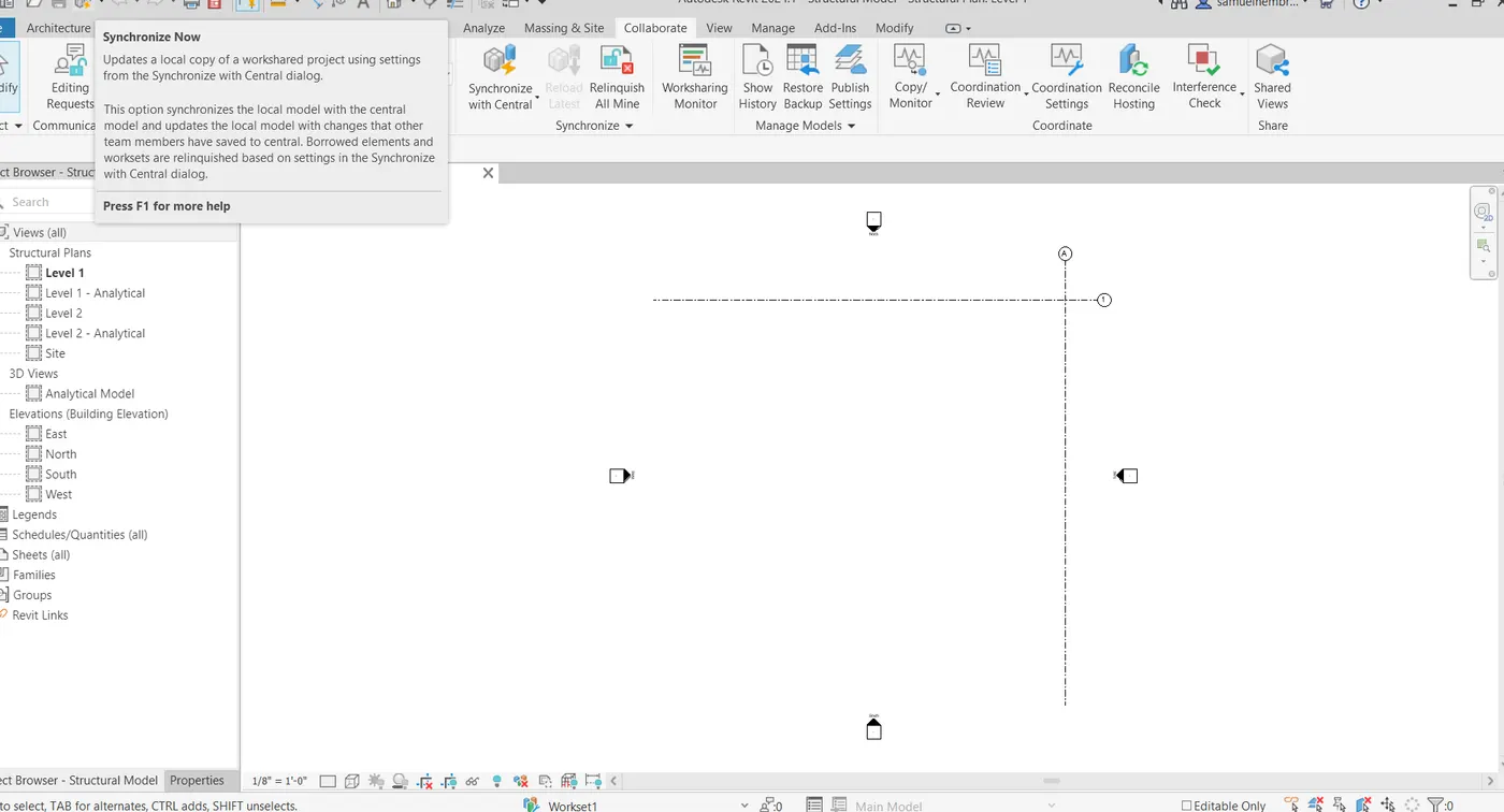
- Use the "Synchronize Now" icon next to save button for synchronizing the file.
Step -IV:-
- Repeat step III for the Structural Model too.
Step - V:-
Step -VI:-
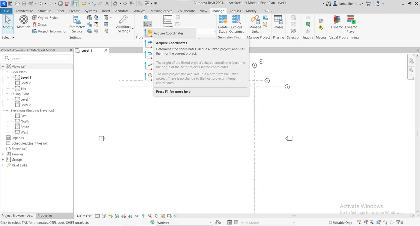
Step -VII:-
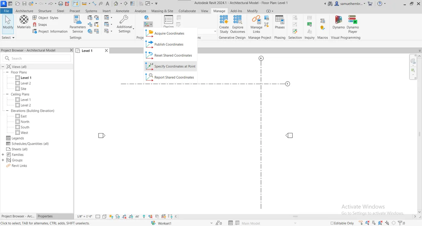
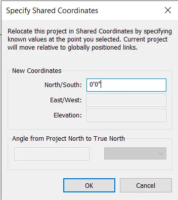
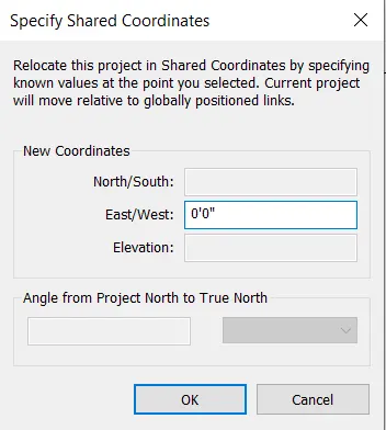
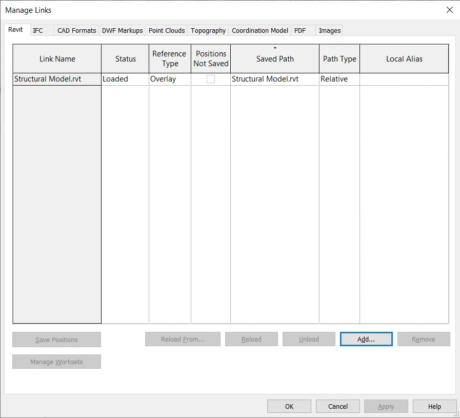
- Relocate the project by following the below path given.
- Manage -> Project Location -> Relocate Project.
- Using cursor select intersecting points of architectural and structural grids, so that they overlap each other.
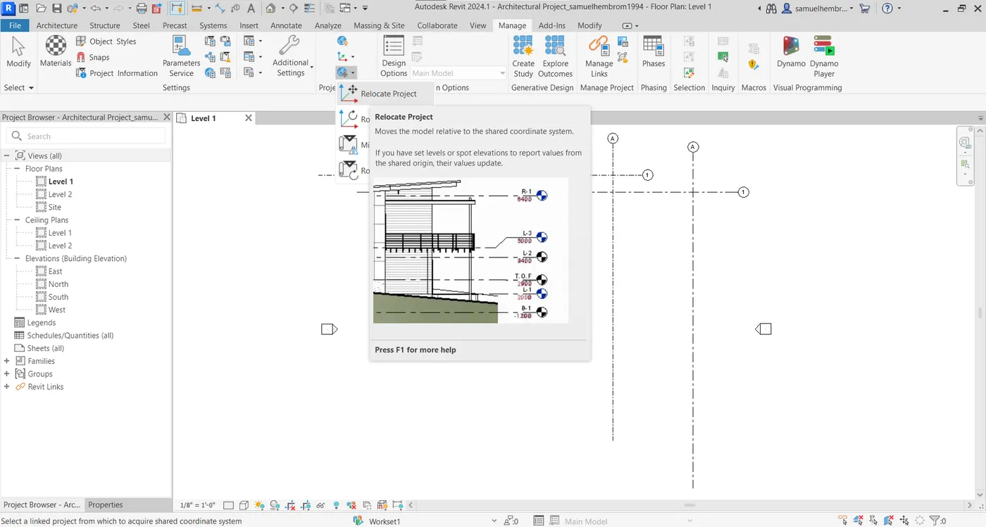
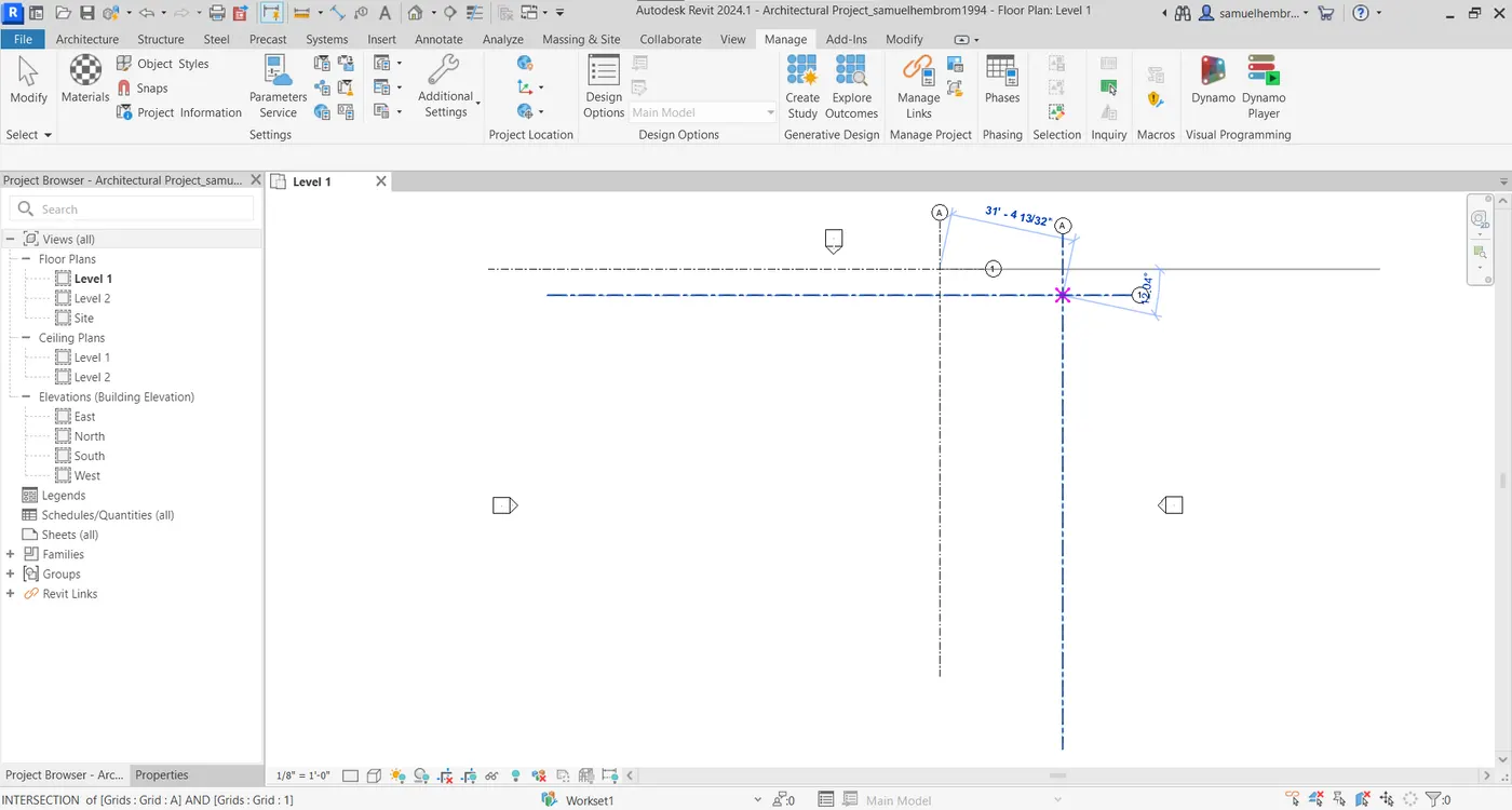
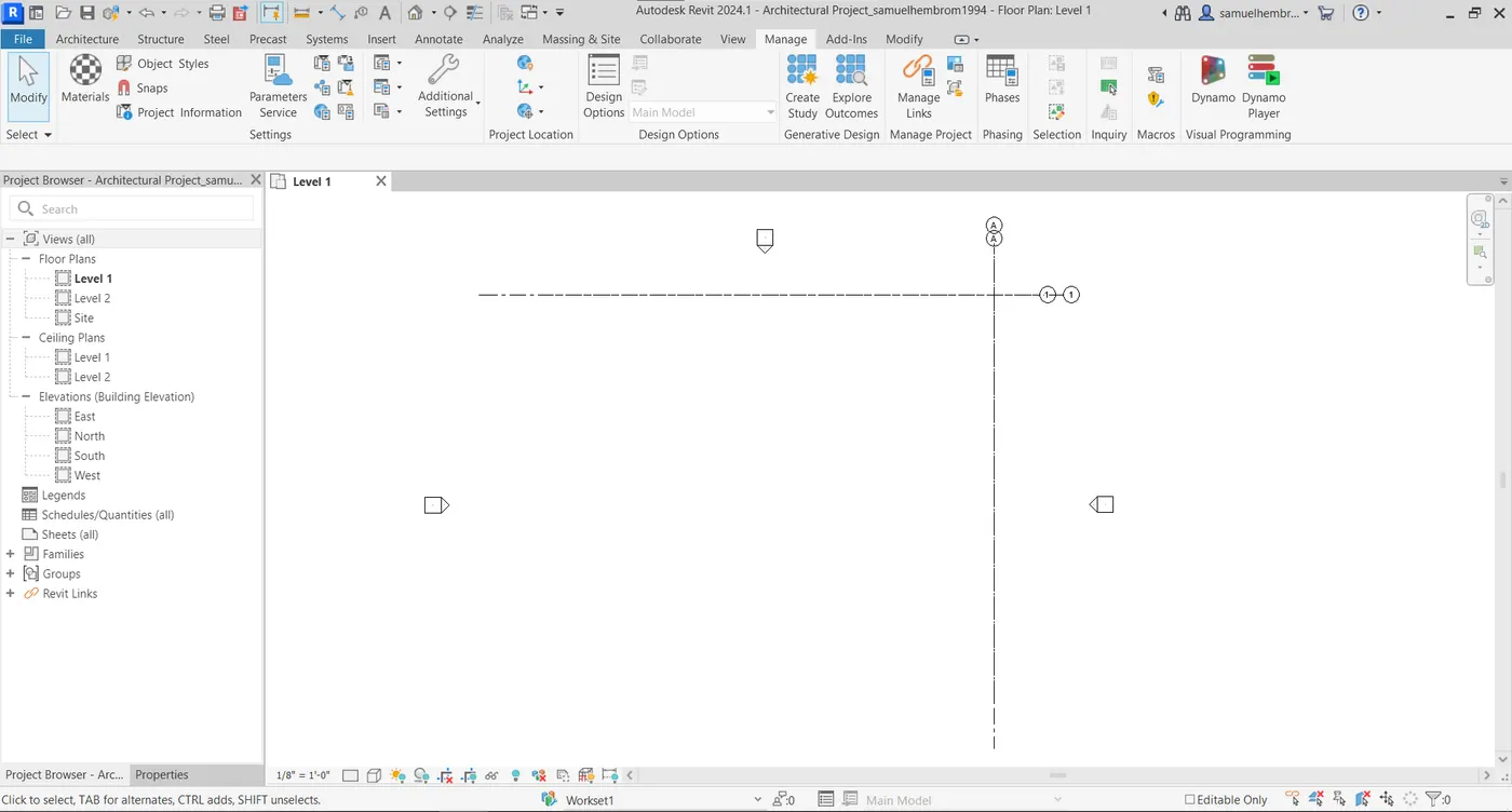
Step -VIII:-
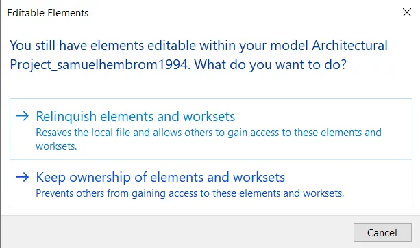
- Before closing the Architectural tab, I have kept ownership of elements and work sets.
- Open linked structural file for creating structural elements.
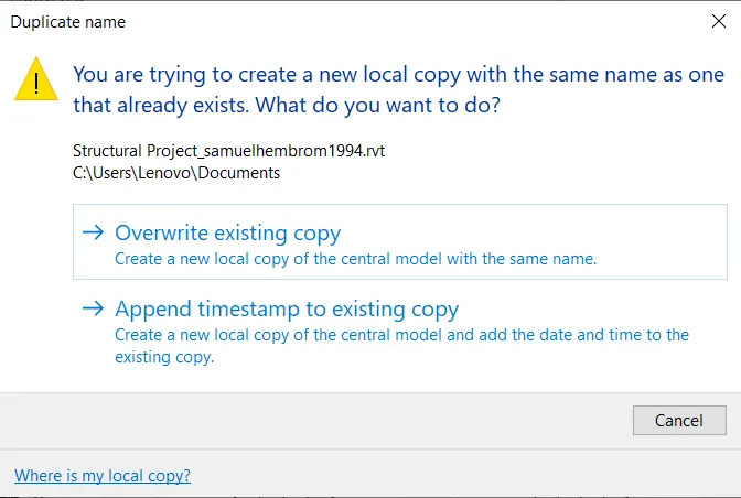
- "Duplicate Name" tab will appear in which I have selected "Overwrite existing copy" option.
Step - IX(For Creating Grids):-
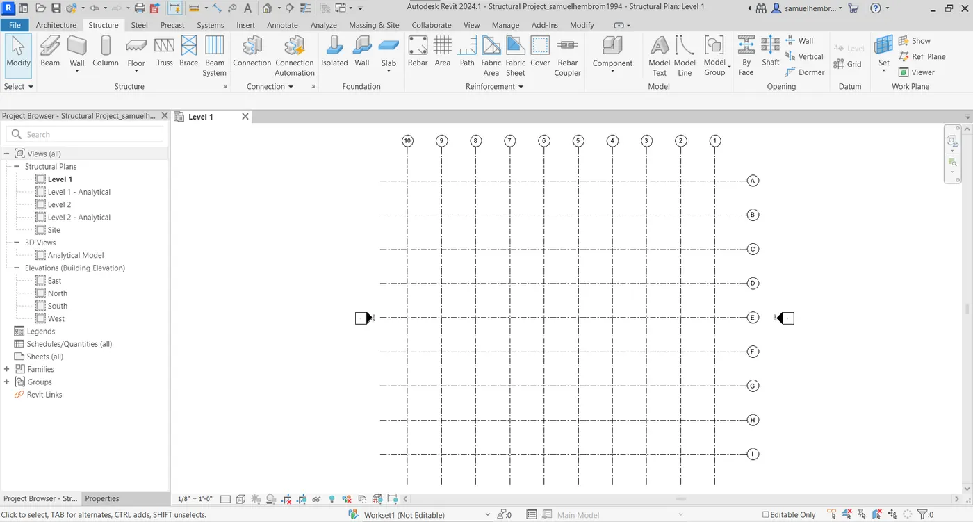
- Go to Structure -> Datum -> Grid.
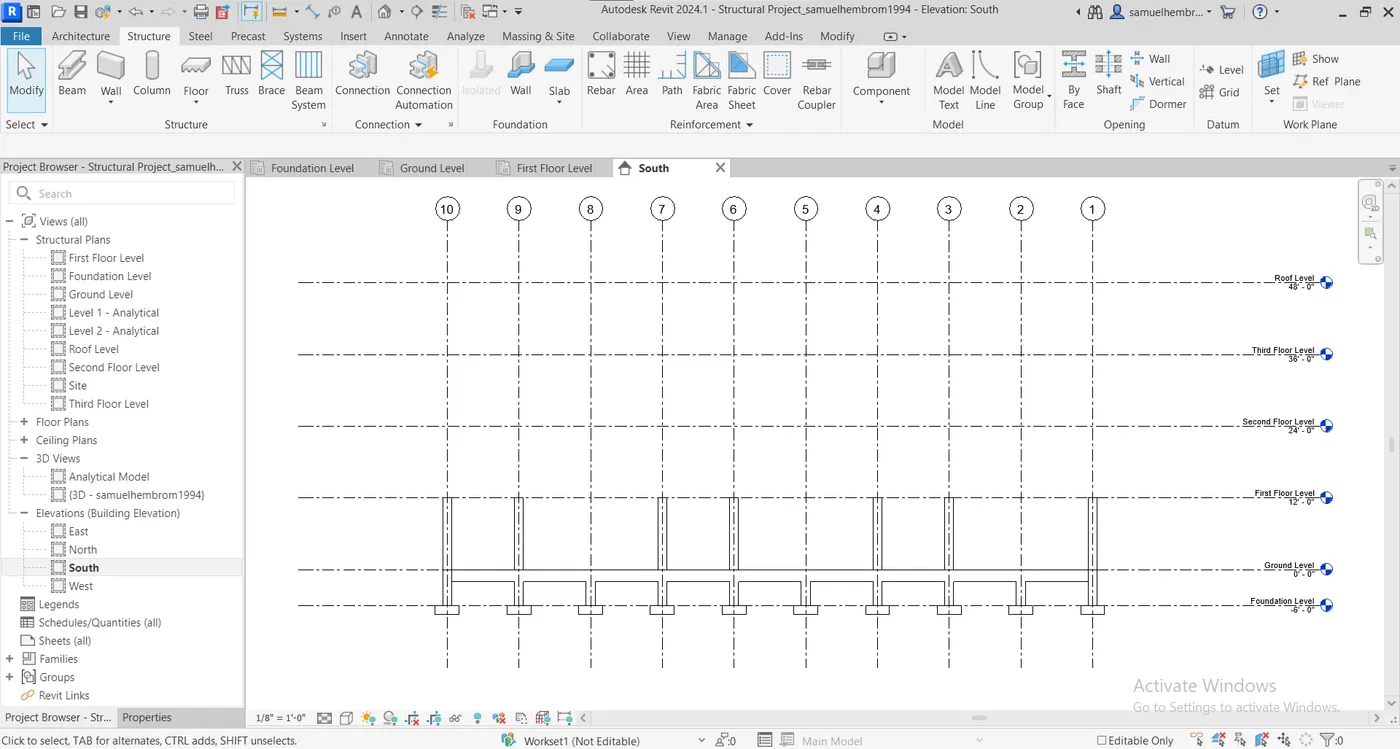
- Draw Vertical and horizontal grids and name them according to general naming convention at a distance of 12' from each other. Also draw the grid lines at foundation level.
- Name horizontal grids alpha numerically and vertical grids numerically.
Step - X(For Creating Levels):-
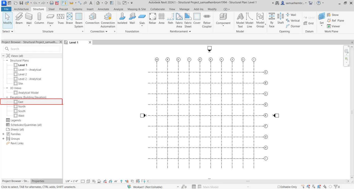
- Go to Project Browser and select North from Elevation (Building Elevation) section.
- Go to Structure -> Datum -> Level.
- Draw levels having Ground Floor level at 0'0" from ground and above levels up to Roof level at 12' apart from each other and Foundation level at 6' apart from ground level.
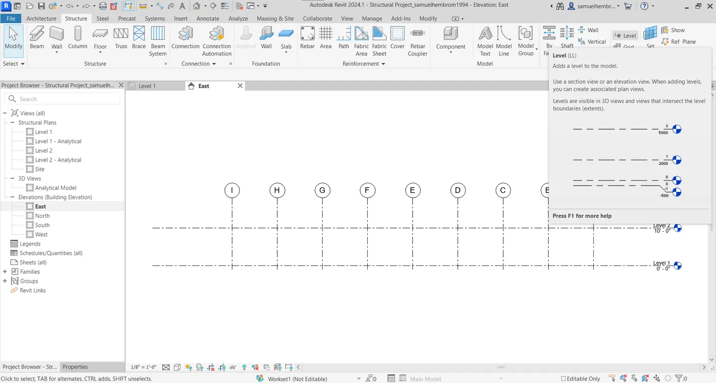
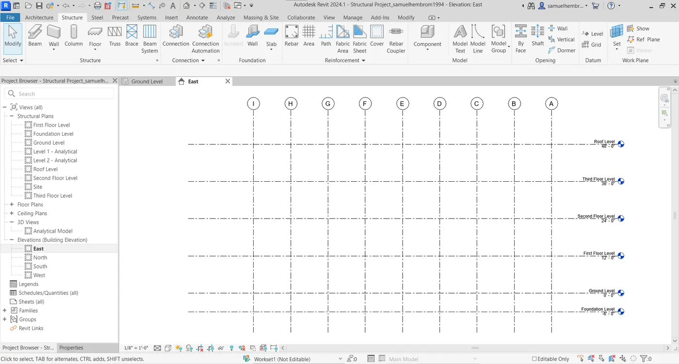
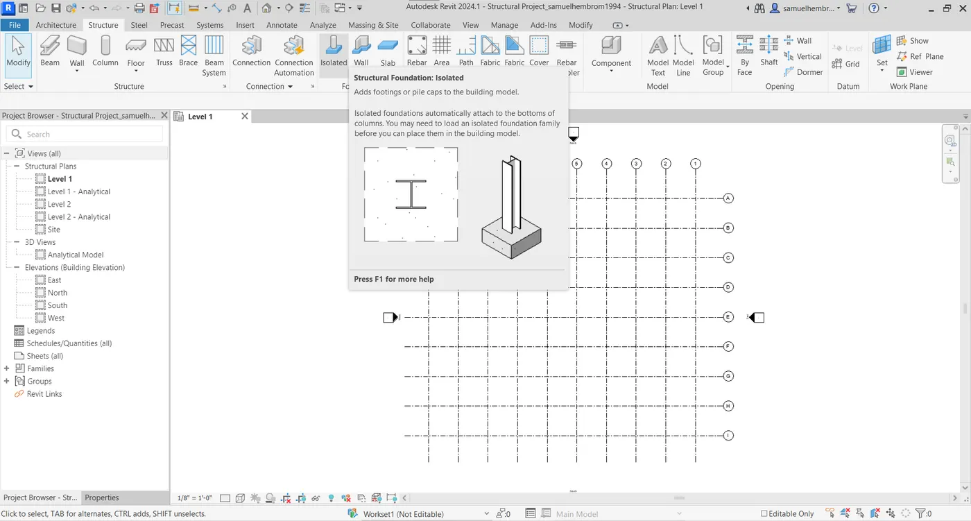
Step - XI(For Creating Columns):-
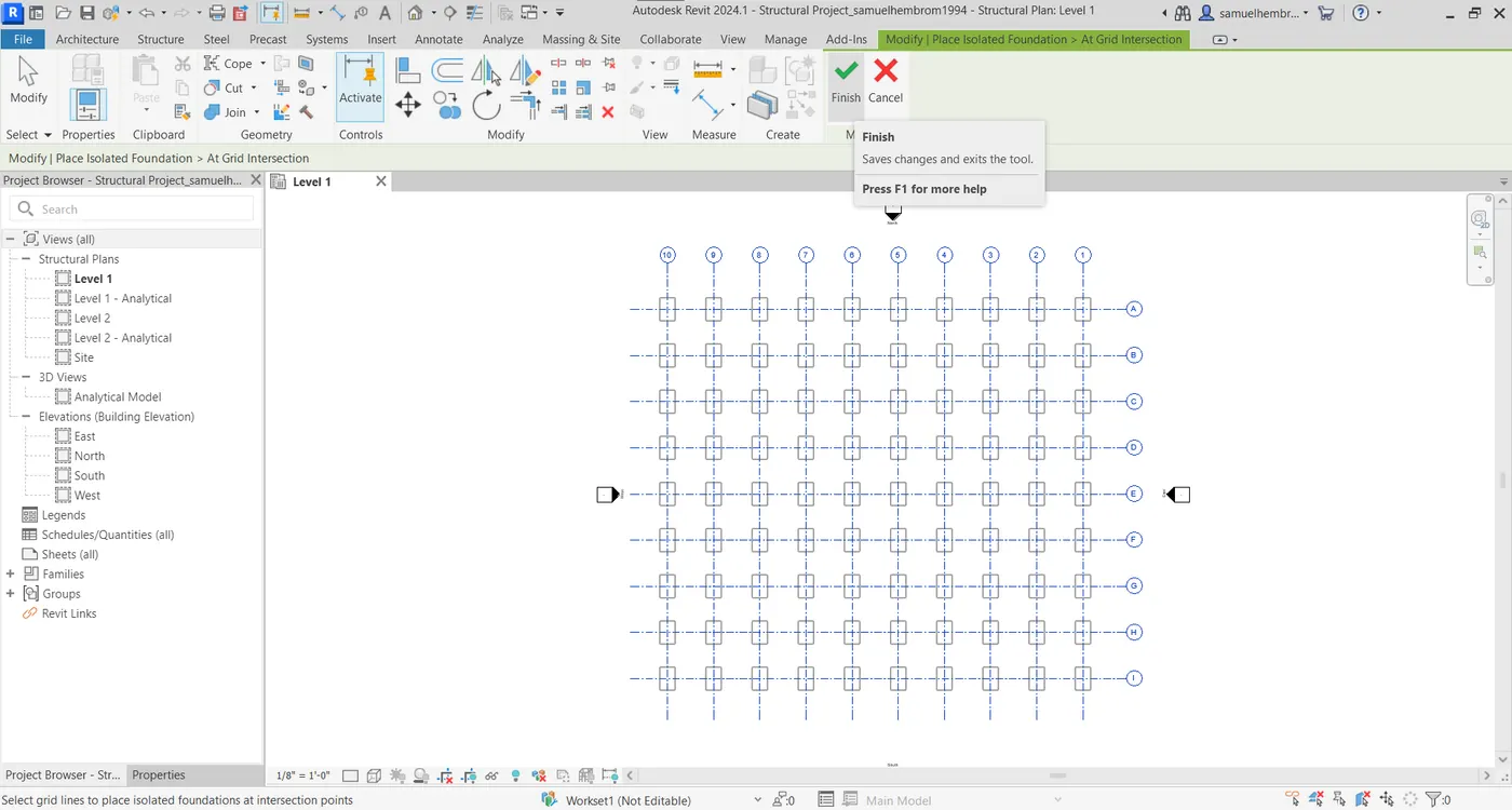
- Go to Structure -> Foundation -> Isolated and choose the level at foundation level.
- Go to Modify/Place Isolated Foundation -> Multiple -> At grids.
- Press Ctrl button and select the grids for placing the footings.
- Go to Modify/Place Isolated Foundation -> At Grid Intersection -> Multiple -> Finish.
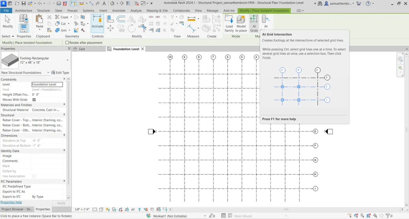
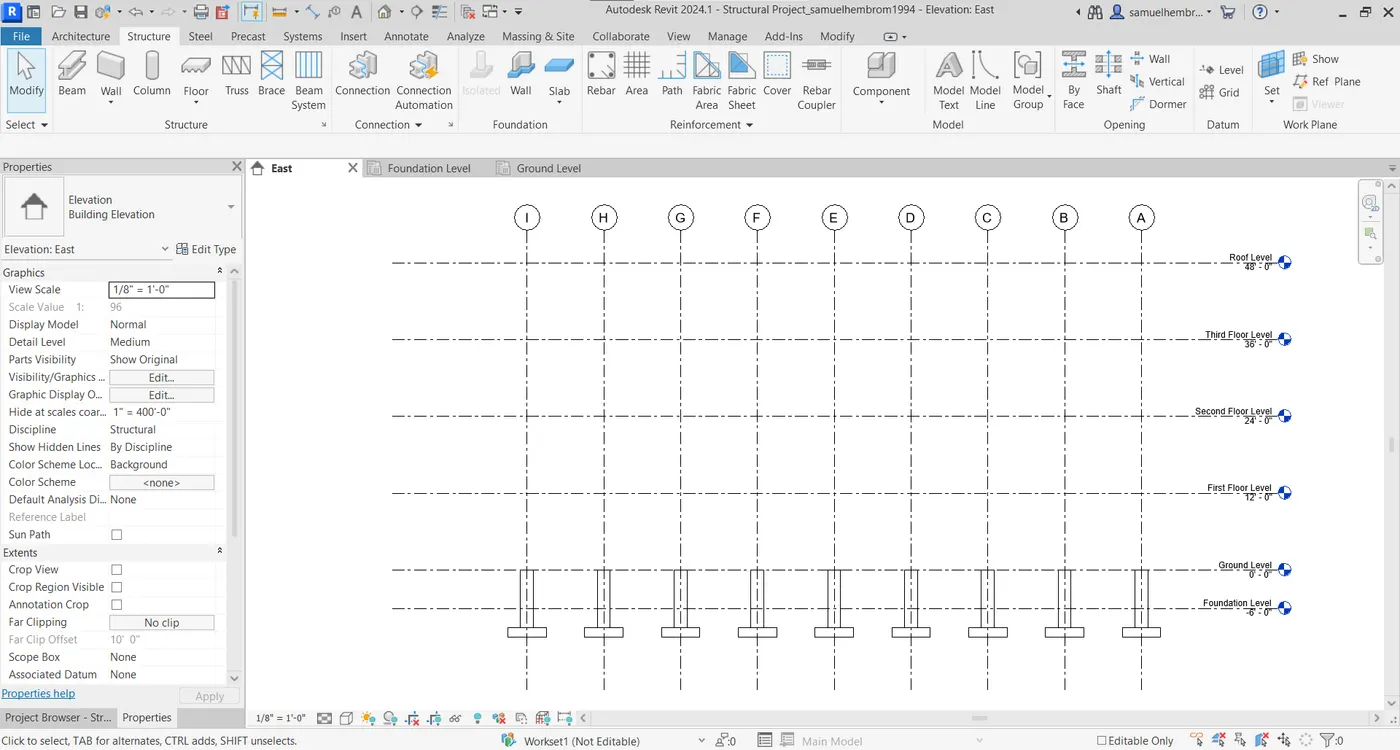
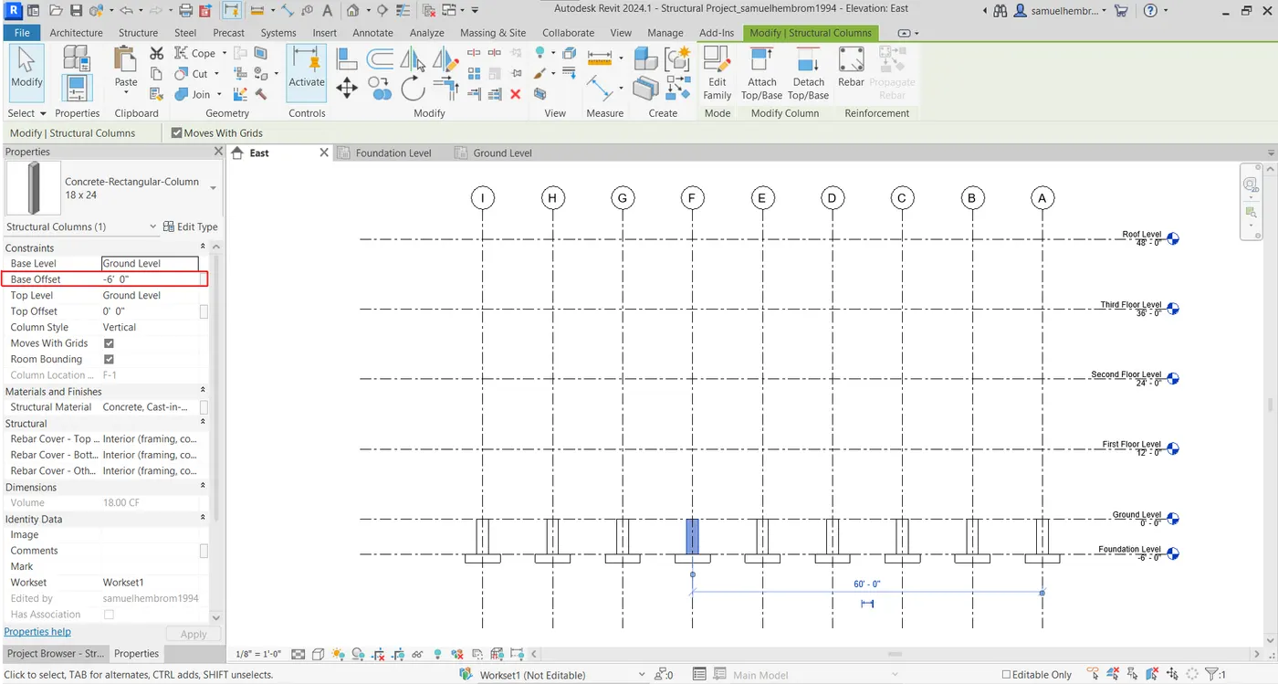
- Go to the property browser and change the base offset to -6'0".
Step-XII(For Creating Beams):-
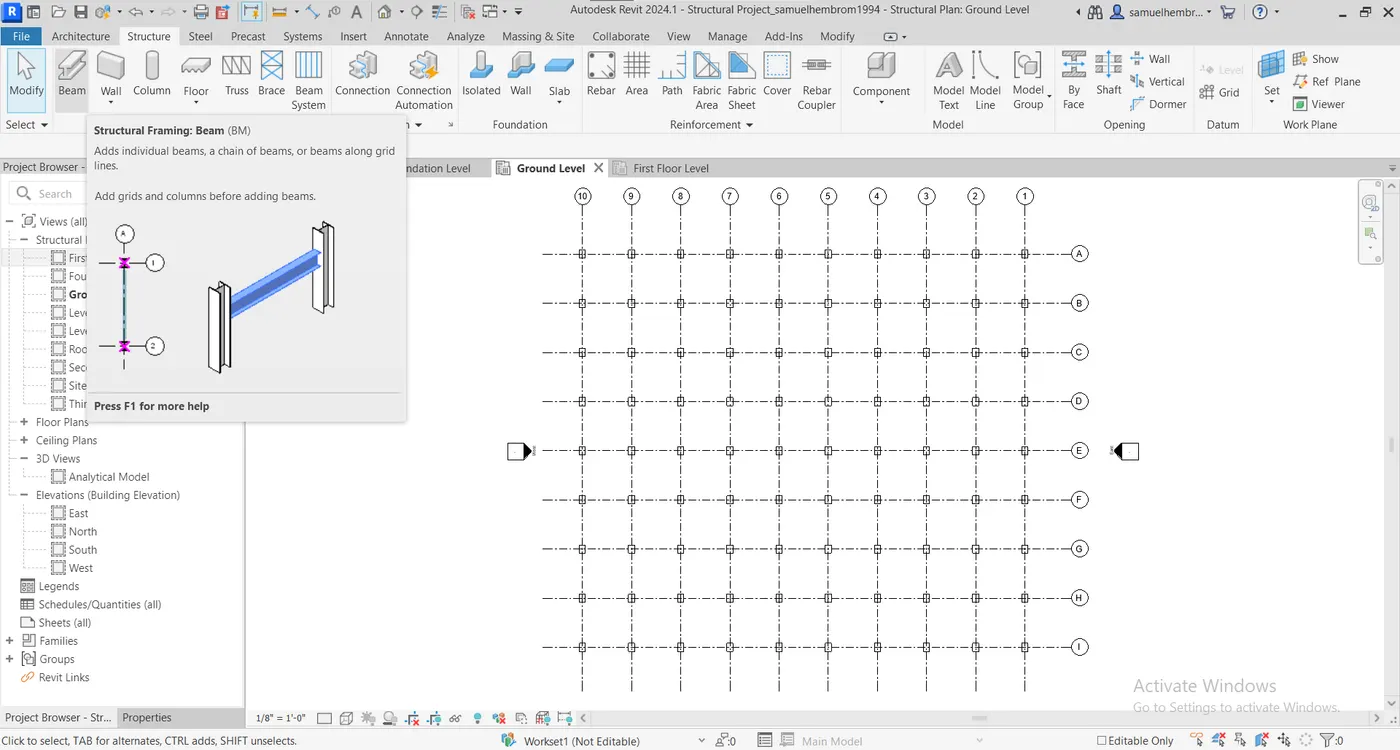
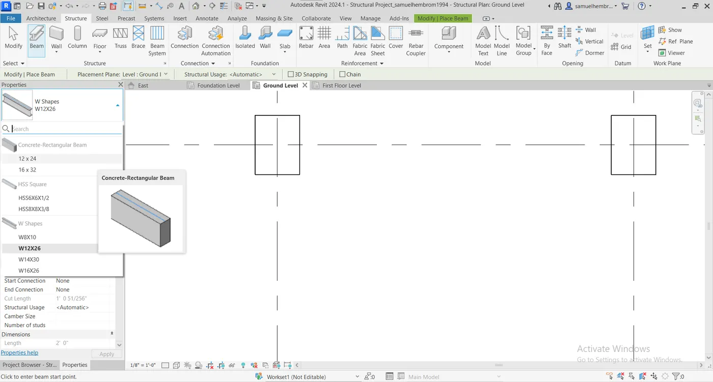
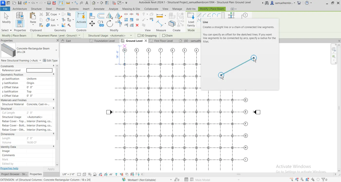
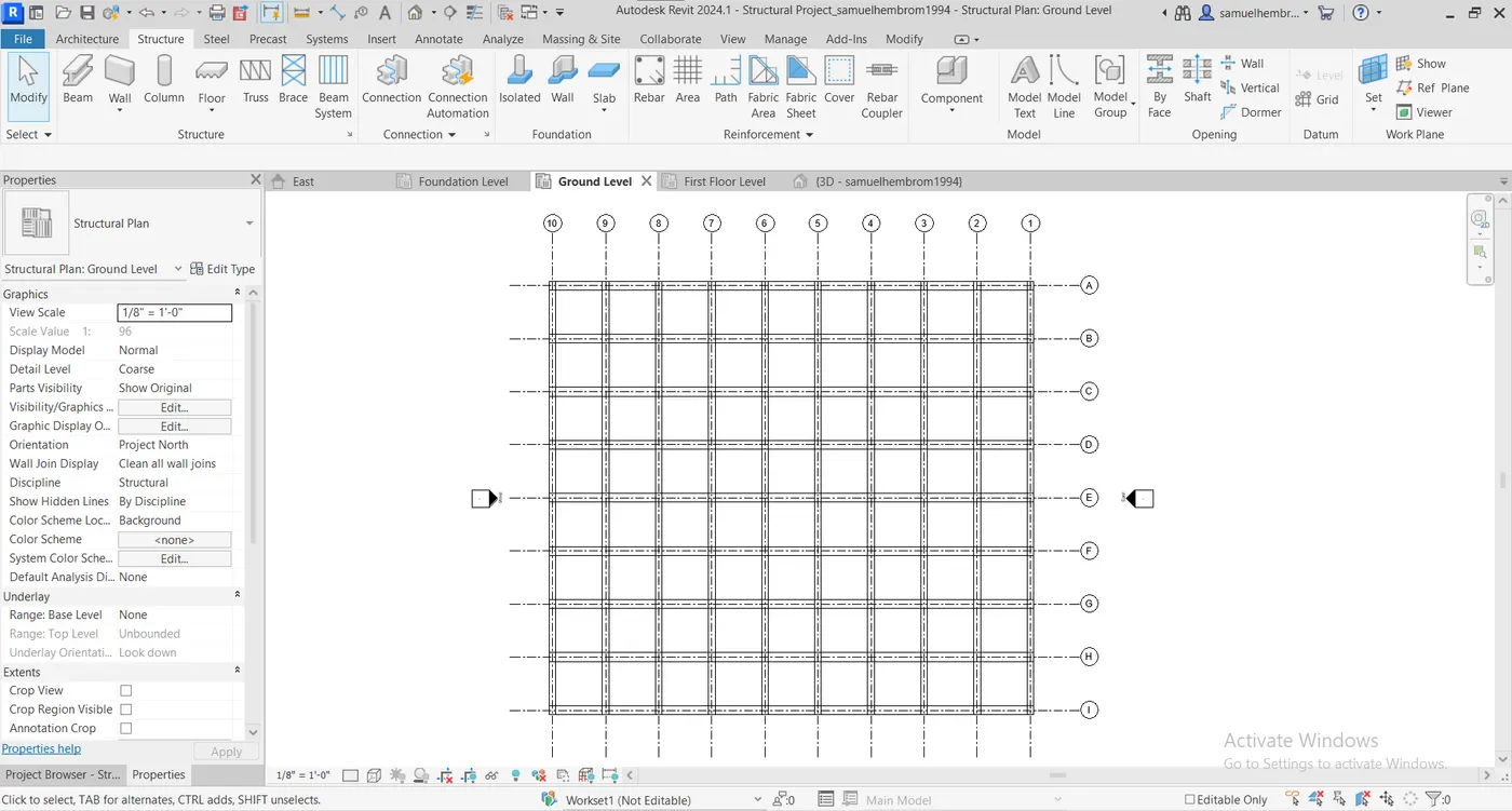
- First we draw beams at ground floor level.
- Go to Structure -> Structure -> Beam.
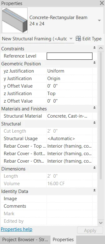
- From the properties browser choose concrete-Rectangular Beam 12X24.
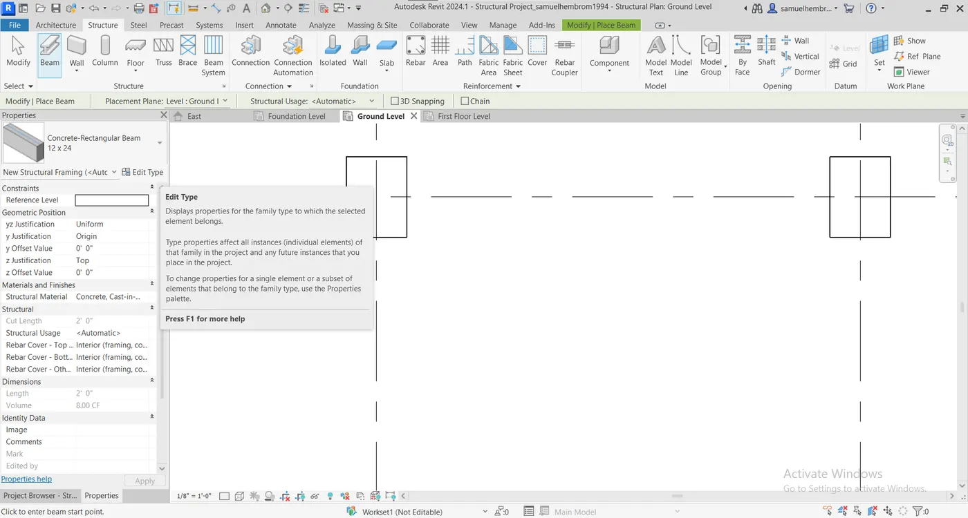
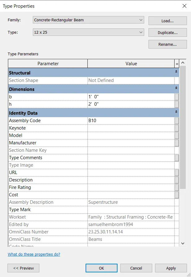
- From the properties browser select edit type option.
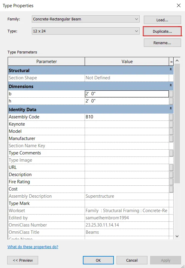
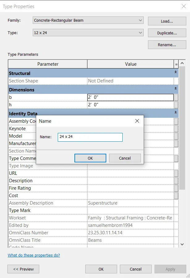
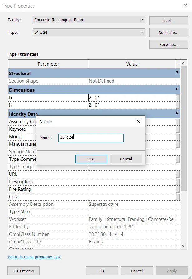
- From the "Type Properties" tab click on "Duplicate" button and give name as 24 X 24.
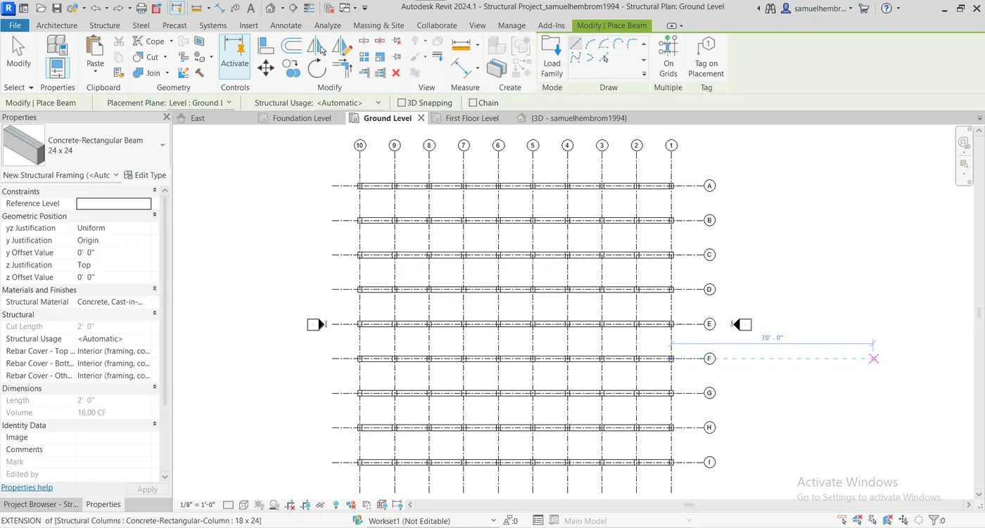
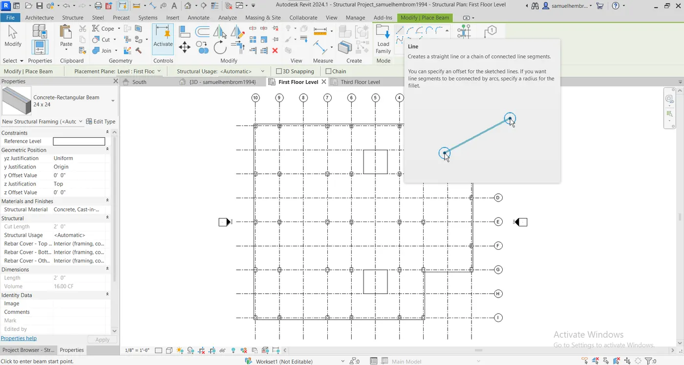
- Go to Modify/Place Beam -> Draw -> Line.
- Draw horizontal grids.
- Similarly draw vertical grids of dimension 18 X 24.
Step-XIII(For creating columns and beams in first floor):-
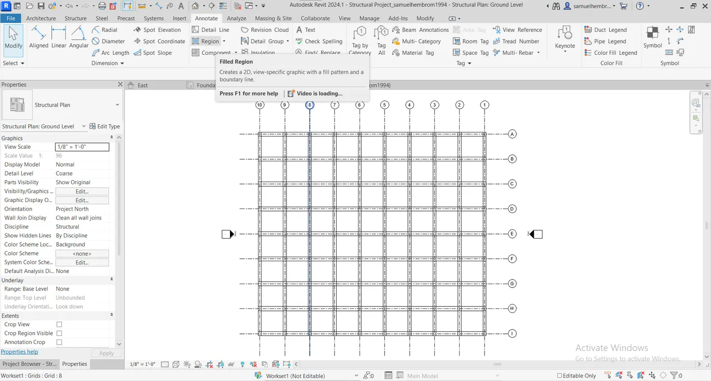
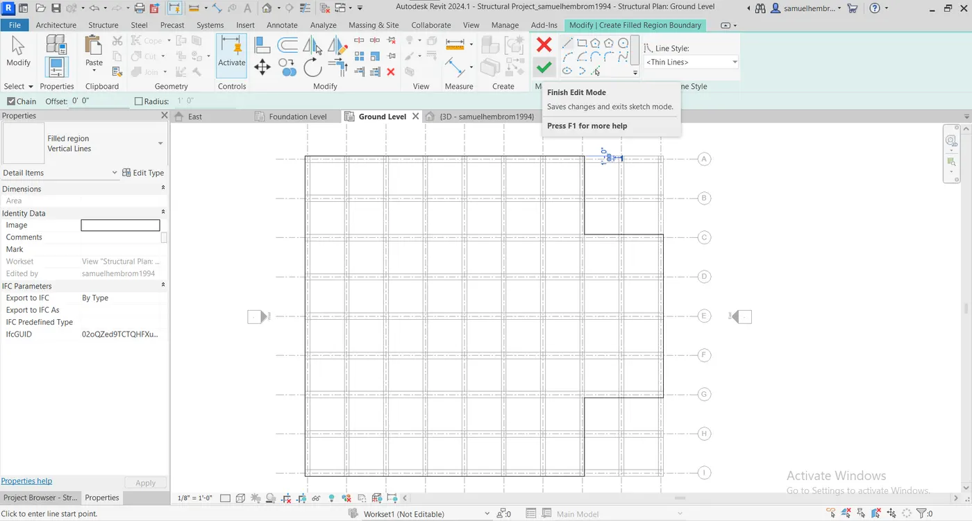
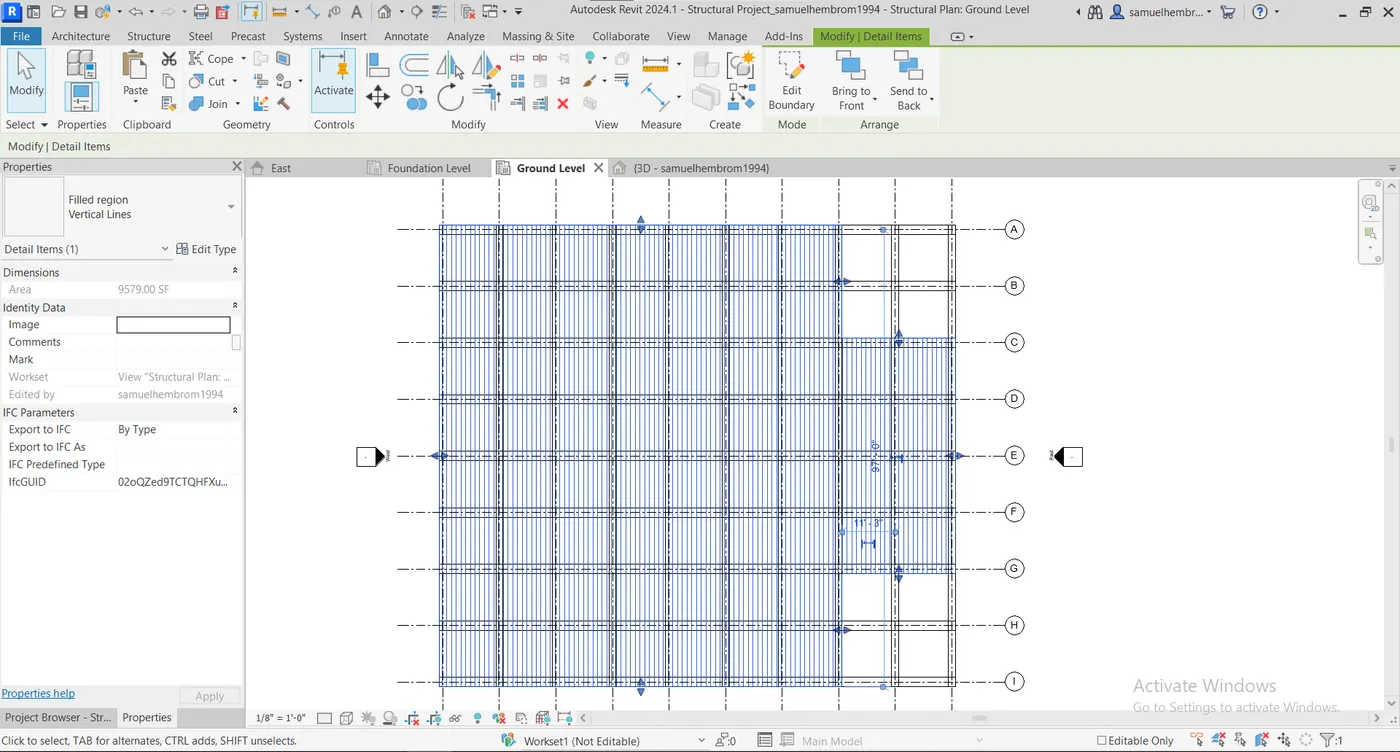
- Create a region covering floor area.
- For that go to Annotate -> Detail -> Region.
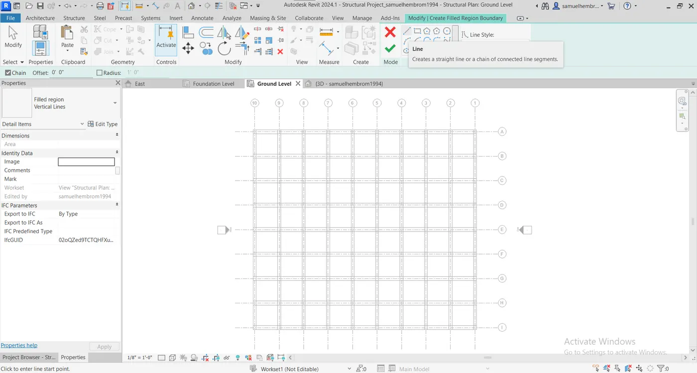
- Go to Modify/Create Filled Region Boundary -> Mode -> Finish Edit Mode.
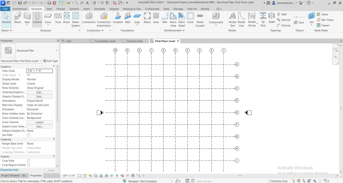
- Go to Structure -> Structure -> Column.
- Place columns on the first floor level.
Step-XIV(For creating Floor):-
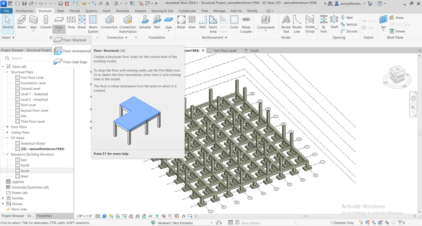
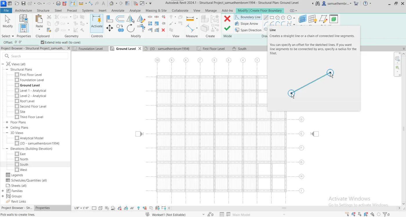
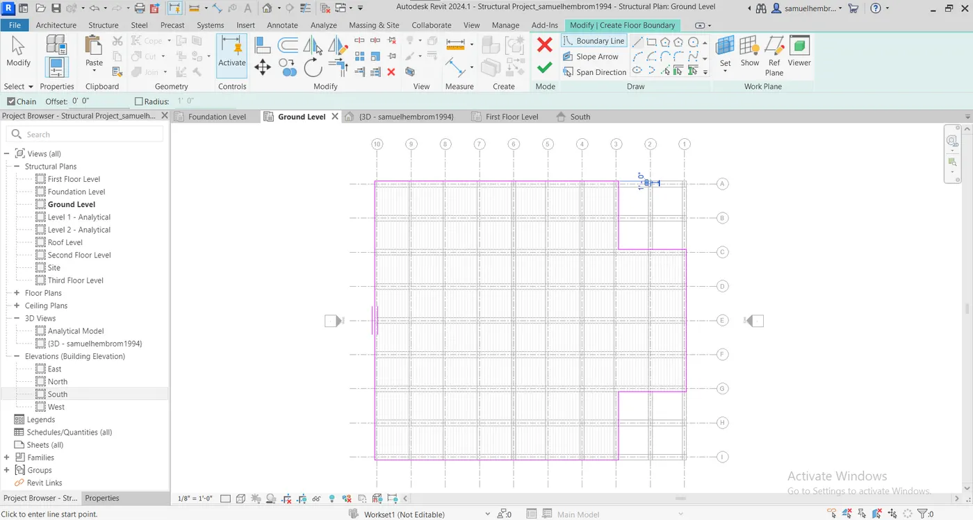
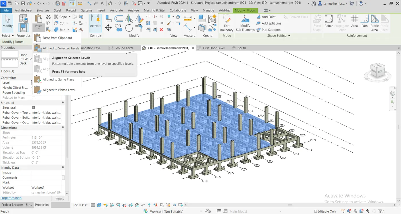
- Go to Structure -> Structure -> Floor -> Floor: Structural.
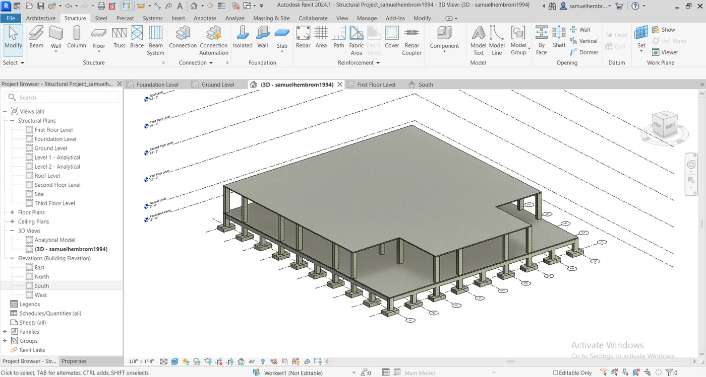
- Draw a floor on ground floor level.
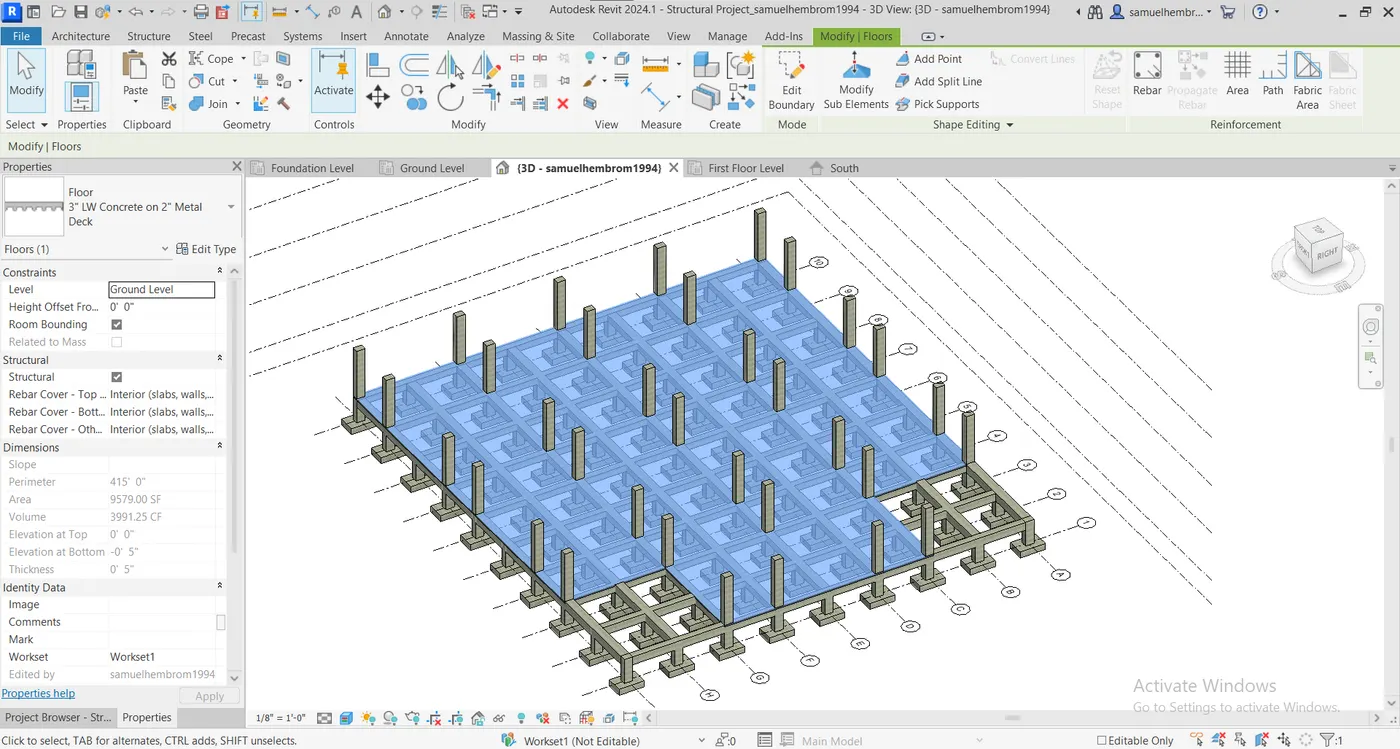
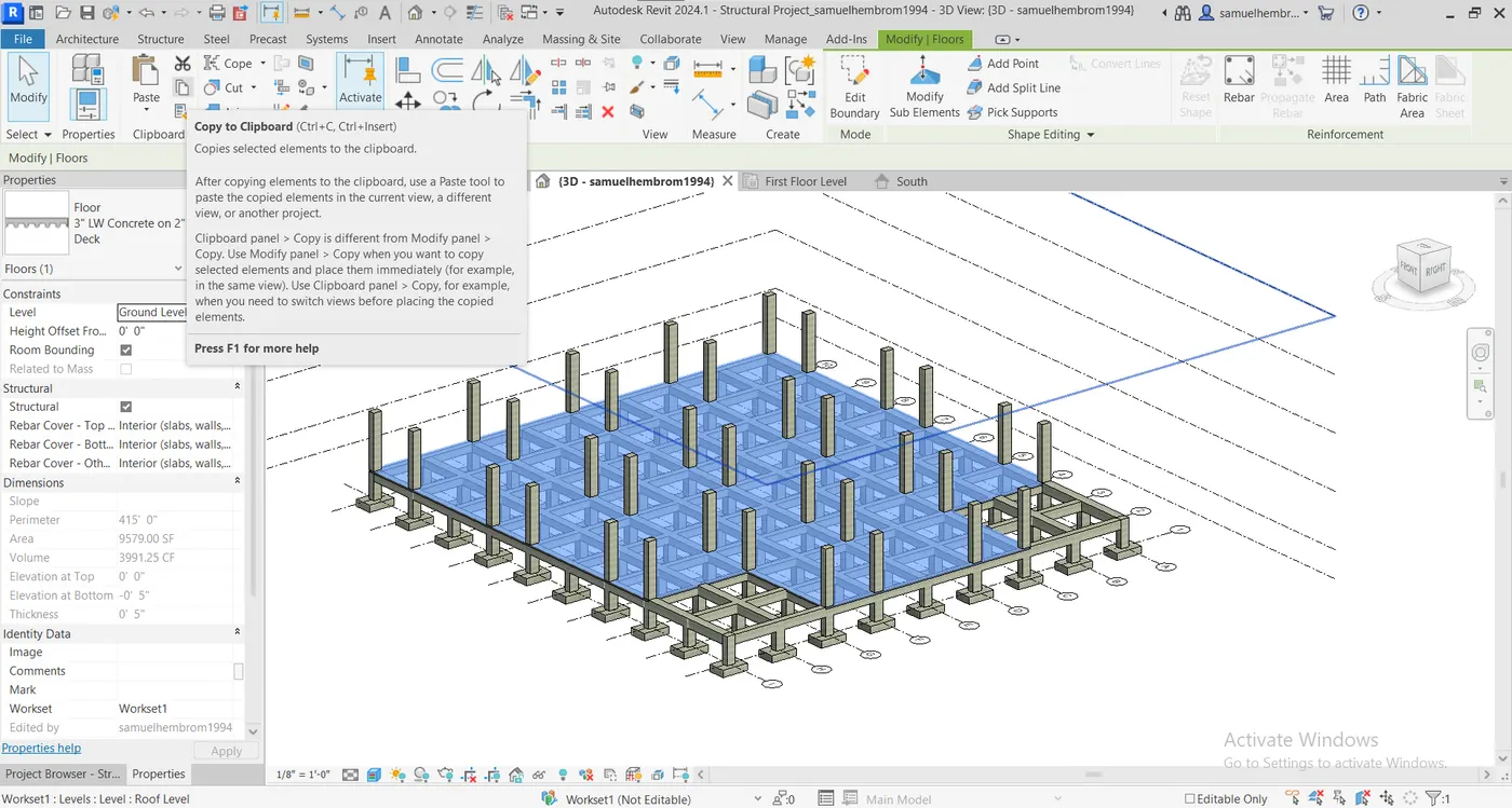
- Go to Modify/Floors -> Clipboard -> Copy to Clipboard.
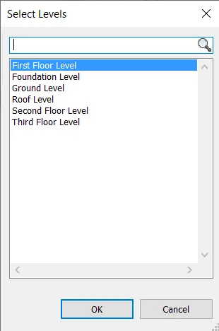
- Go to Modify/Floors -> Clipboard -> Paste -> Aligned to selected levels.
- Select First Floor Level from the "Select Levels" dialogue box.
- Edit the boundary of ground floor level floor.
Step-XV(For copying floors and columns up to third floor):-
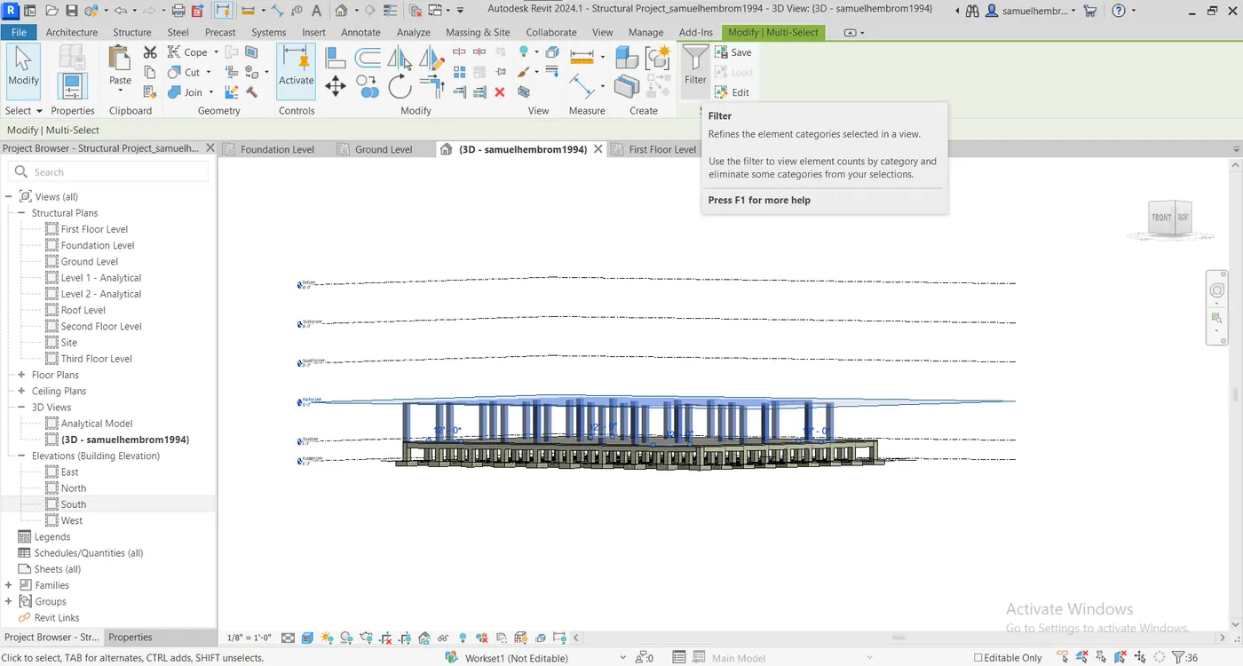
- Select first floor level elements.
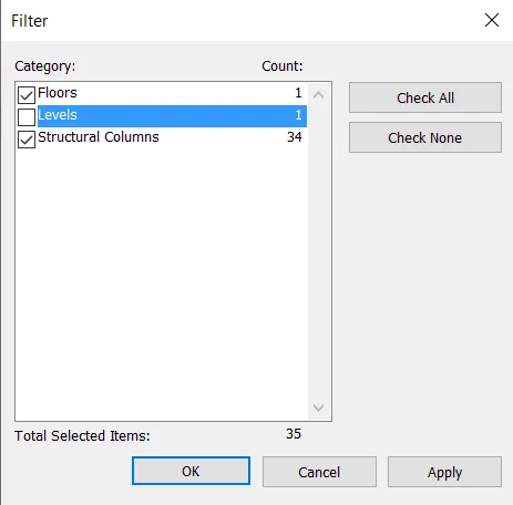
- Go to Selection -> Filter.
- Uncheck "Levels" from the Filter tab.
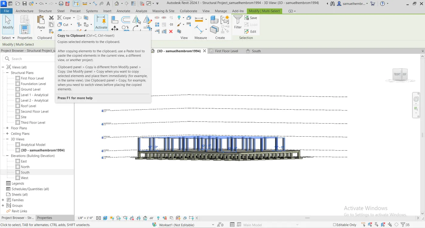
- Go to Modify/Multi-Select -> Clipboard -> Copy to Clipboard.
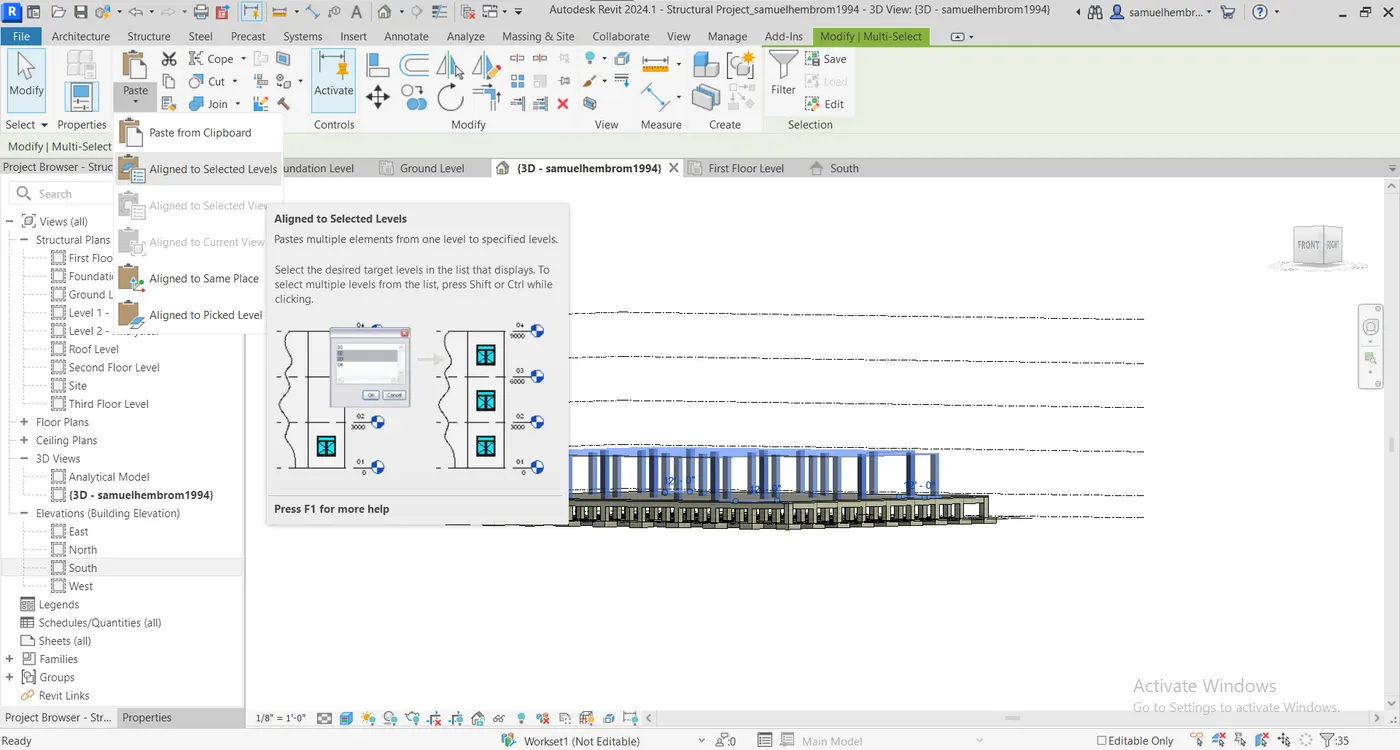
- Go to Modify/Multi-Select -> Clipboard -> Paste -> Aligned to Selected Levels.
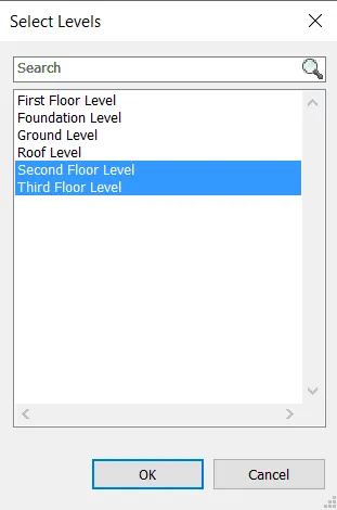
- Select "Second Floor" & "Third Floor" from Select Levels tab.
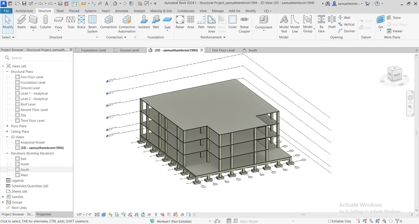
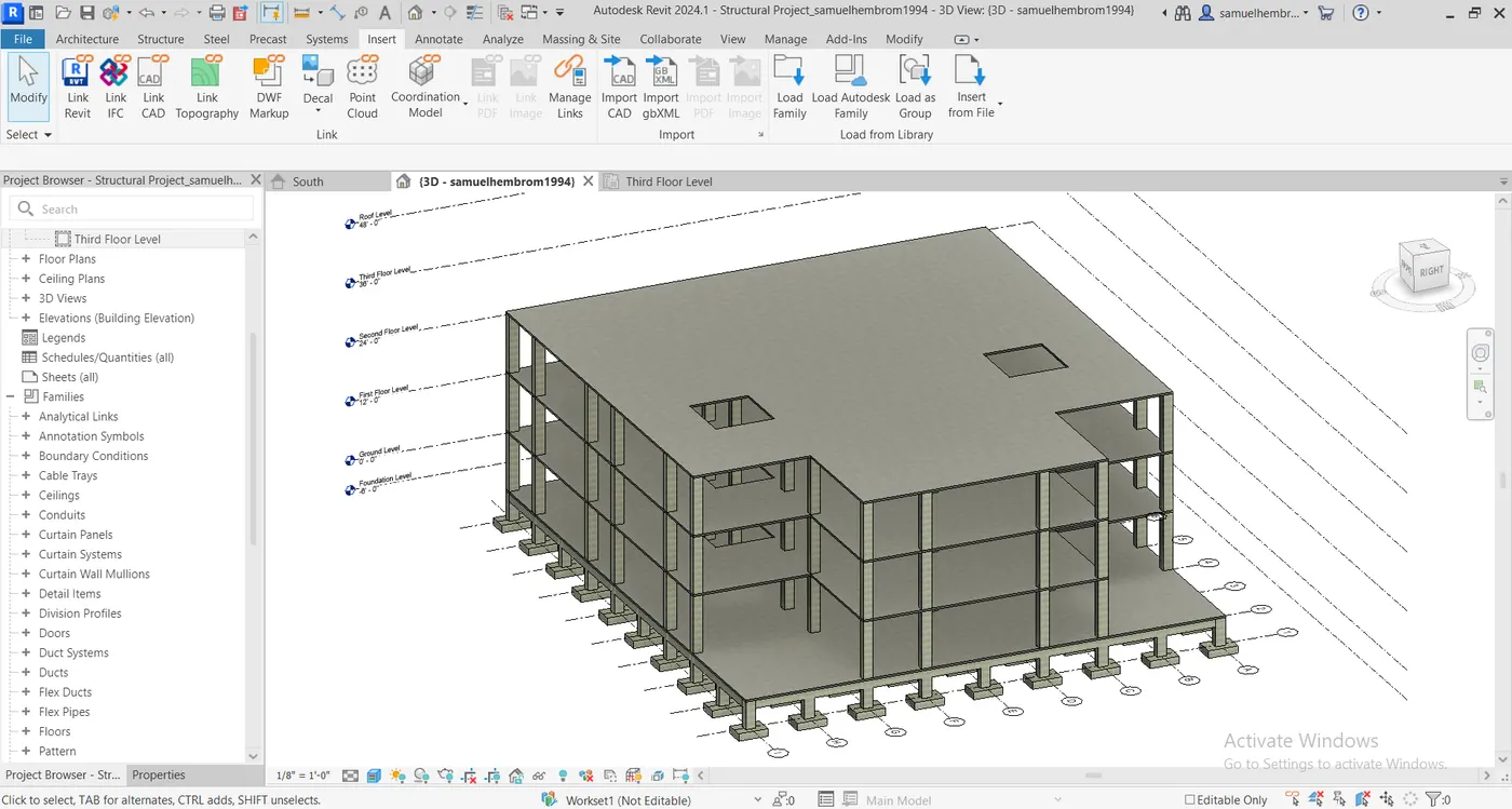
Step XVI(Creating Opening for elevator):-
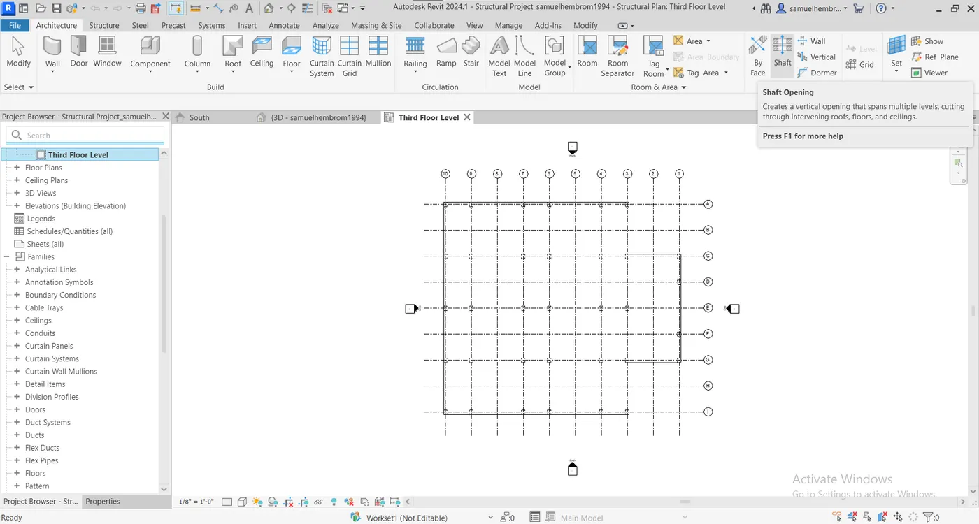
- Go to Architecture -> Opening -> Shaft.
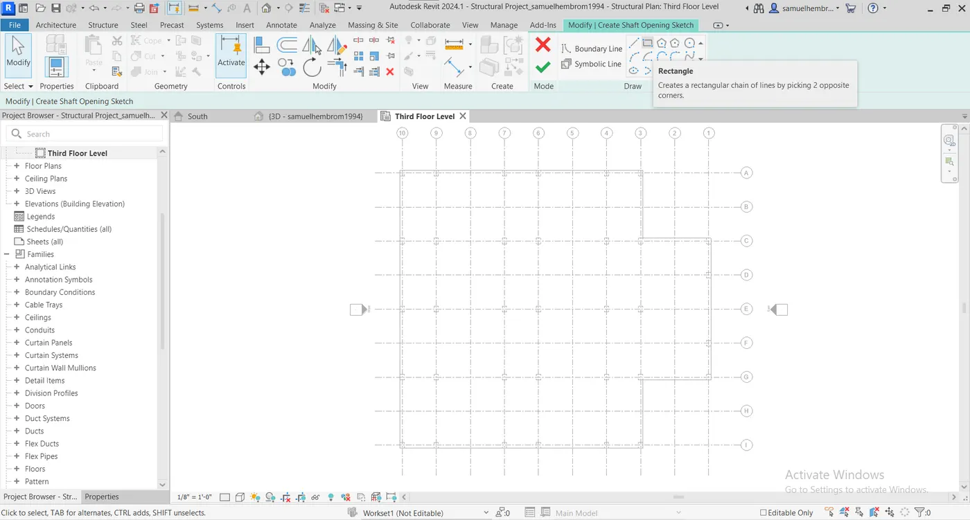
- Go to Modify/Create Shaft Opening Sketch -> Draw -> Rectangle.
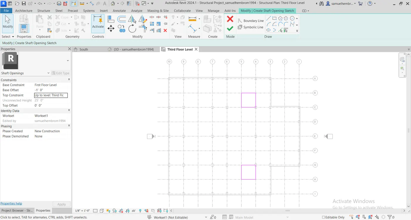
- Draw the boundary of shaft on the third floor plan and select the base constraint and top constraint to first floor and third floor respectively.
Step XVI(Creating Beams):-
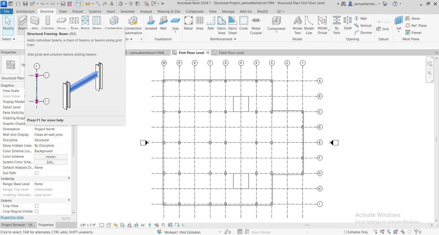
- Go to First Floor Plan.
- Go to Structure -> Structure -> Beam.
- In the properties browser select Concrete-Rectangular Beam (24 X 24).
- Go to Modify/Place Beam -> Draw -> Line and draw horizontal beams.
- Select Concrete-Rectangular Beam (18 X 24) from the properties browser.
- Go to Modify/Place Beam -> Draw -> Line and draw vertical beams.
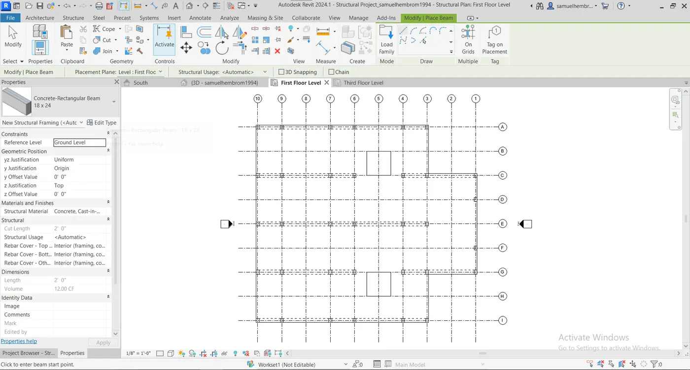
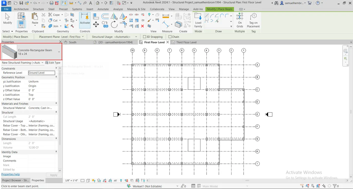
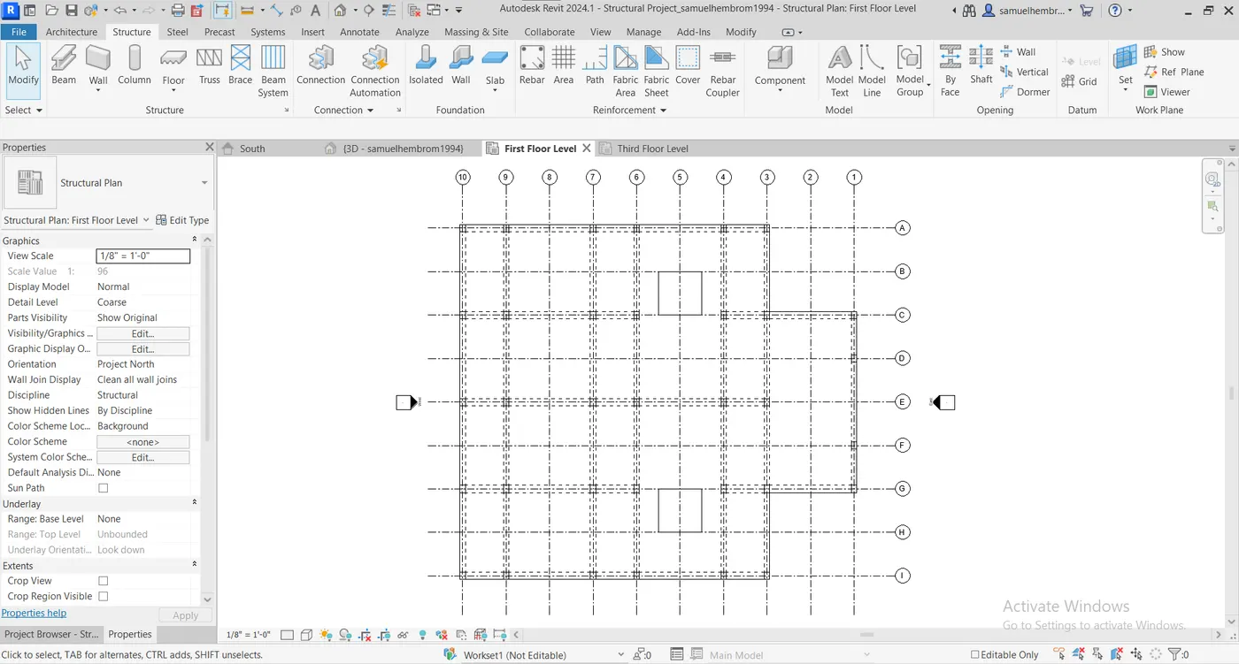
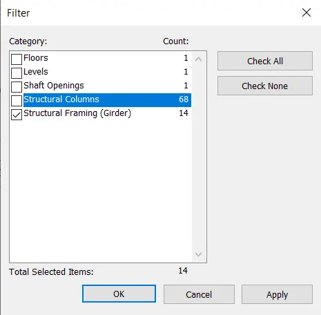
- Select the elements from the First floor level and go to Modify/Multi Select -> Selection -> Filter.
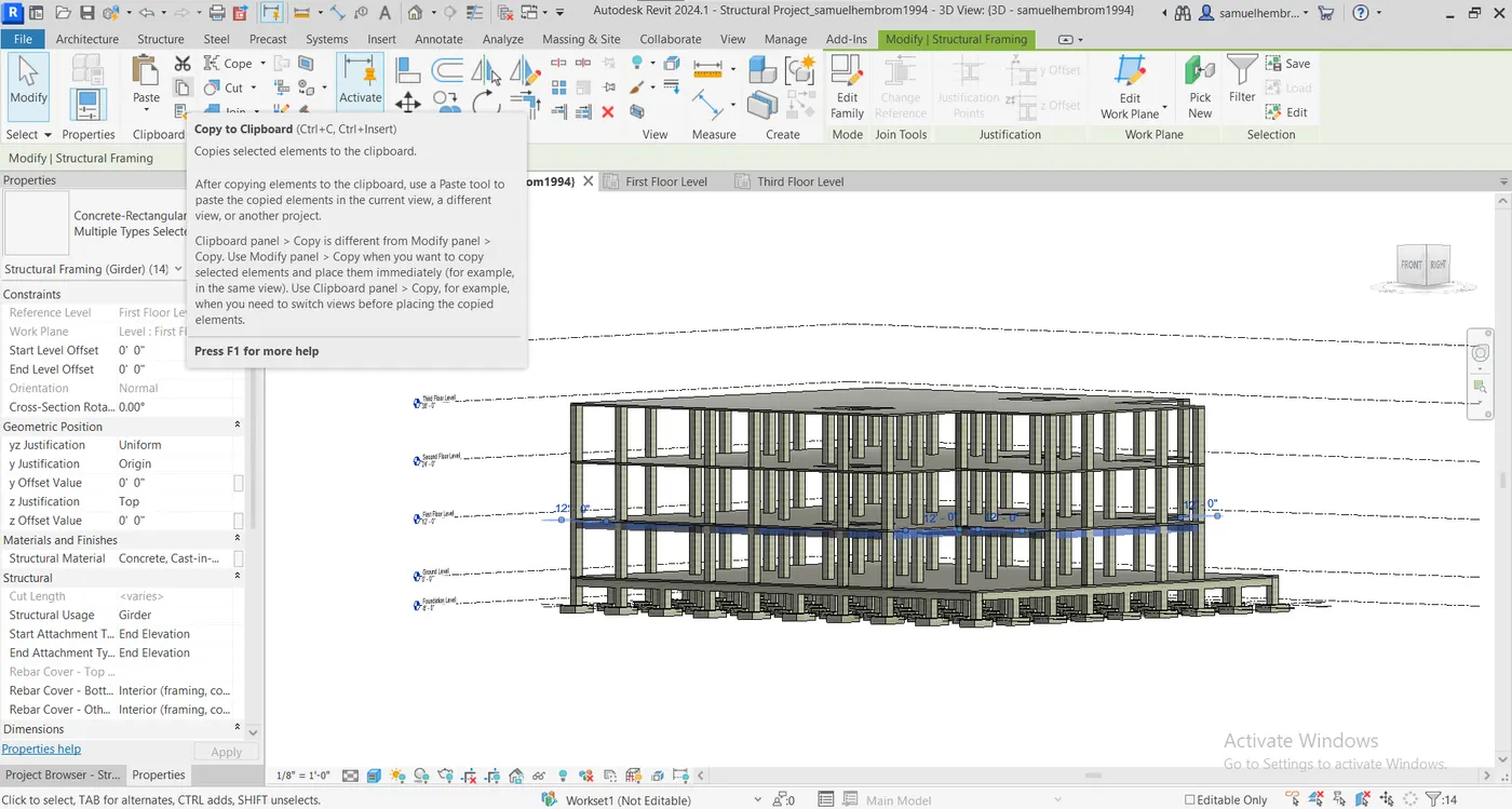
- Uncheck all the elements except Structural Framing (Girder).
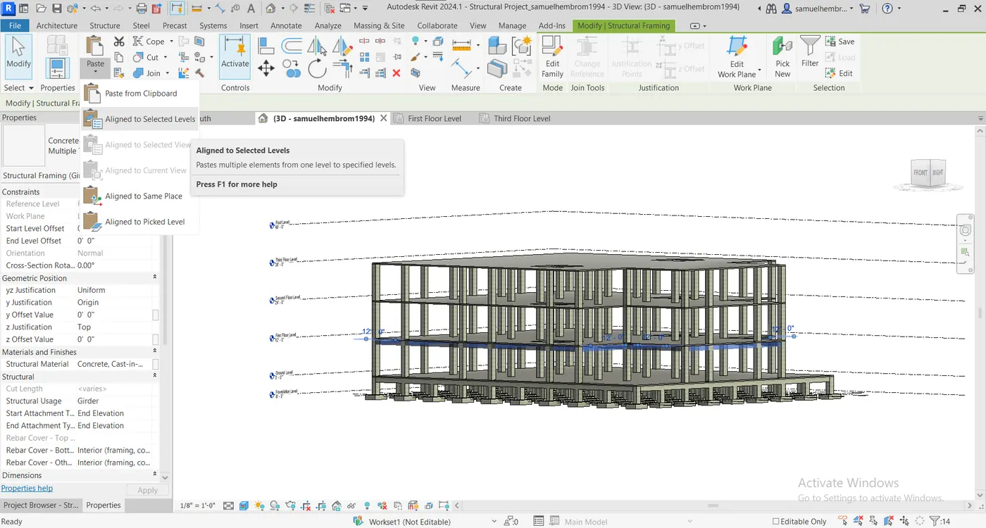
- Now go to Modify/Structural Framing -> Clipboard -> Copy to clipboard.
- Again go to Modify/Structural Framing -> Clipboard -> Paste -> Aligned to selected levels.
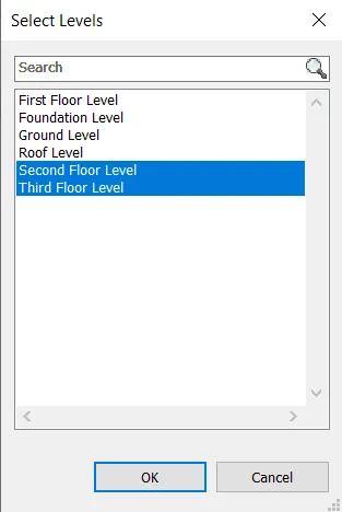
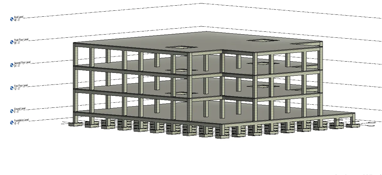
- From the "Select Levels" tab choose second floor and third floor levels.
Step XVI(For structural Framing):-
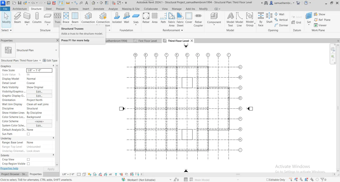
- Go to Third Floor Level plan.
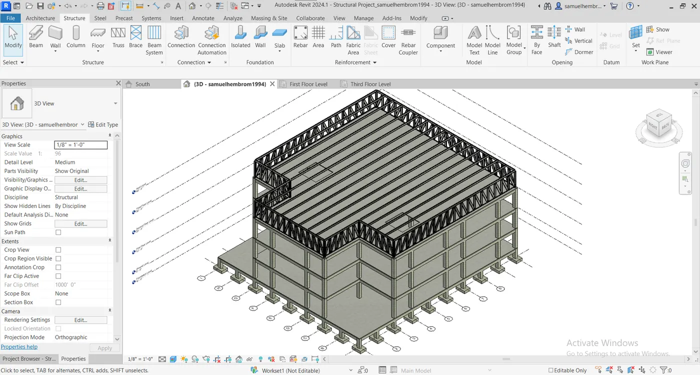
- Go to Structure -> Structure -> Truss.
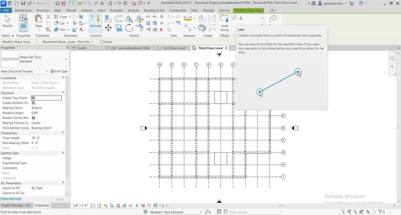
- Go to Modify/Place Truss -> Draw -> Line.
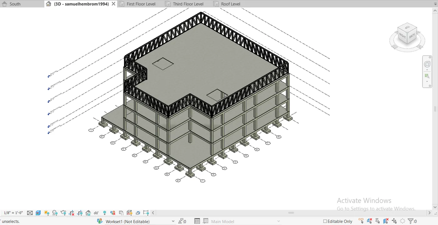
- Draw the line path for providing truss.
Step XVII (For Beam System):-
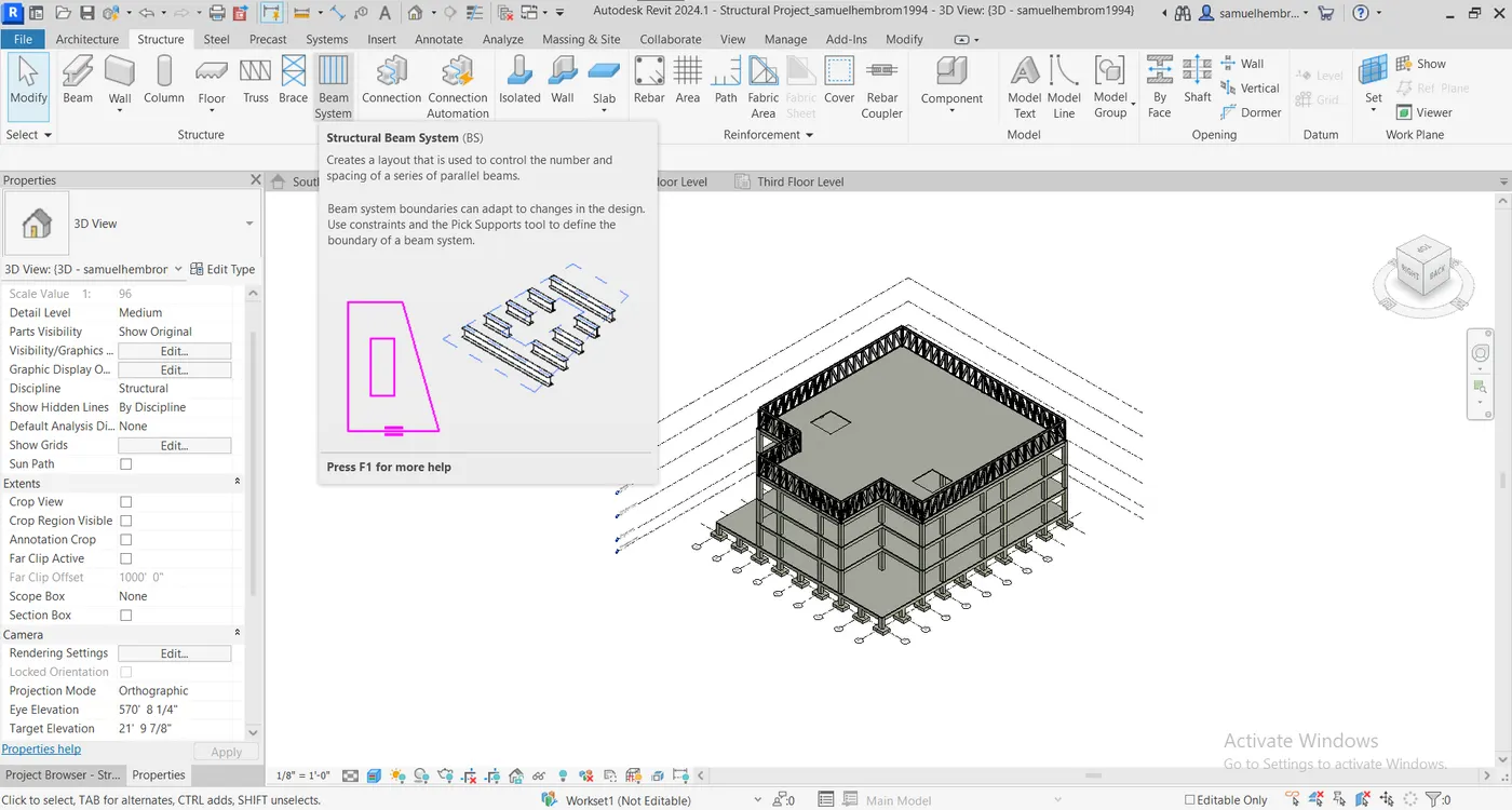
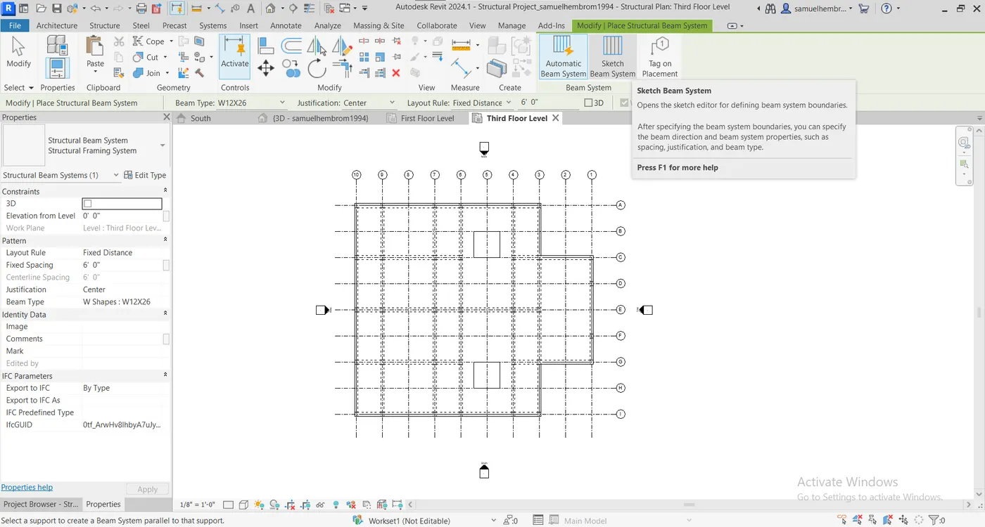
- Go to Structure -> Structure -> Beam System.
- Go to Modify/Place Structural Beam System -> Beam System -> Sketch Beam System.
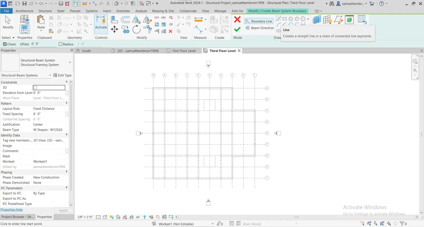
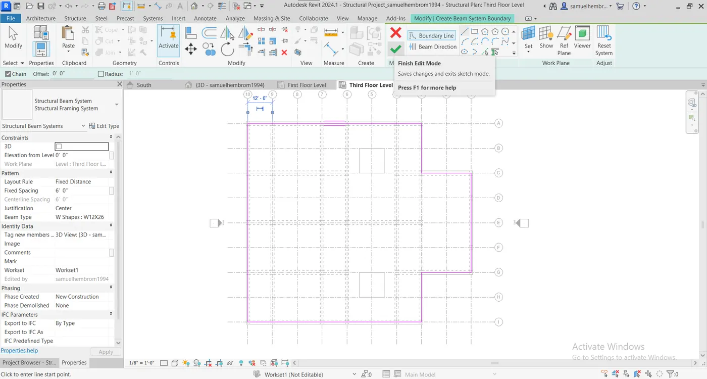
- Again go to Modify/Create Beam System Boundary -> Draw -> Line, and draw the boundary line of beam system.
- Again go to Modify/Create Beam System Boundary -> Mode -> Finish Edit Mode.
Q No:-4
Aim:-
To use the architectural model, including the following components based on the type of structure selected.
a. Wall Layout with appropriate material and finishing.
b. Exterior façade with fancy finish.
c. Interior partition walls to size rooms.
d. Components to add details to a room (Desk, Chair, Lighting, Plumbing fixtures)
e. Add components such as stairs Elevators
f. Have at-least one side of the building with curtain walls and glass panels.
g. Include interior and exterior lighting fixtures.
h. Place proper topographic components from outside (Trees, Parking, Plants) to add details to the model.
Procedure:-
Step I:-
- Save the structural model and synchronize it.
- Close the structural model and open architectural model which is linked with structural model.
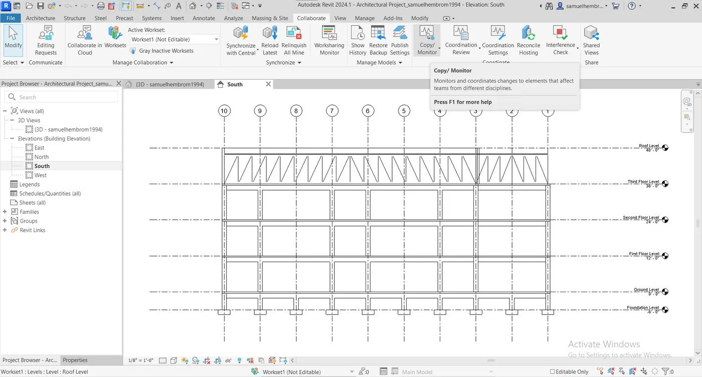
- Open the South Elevation View
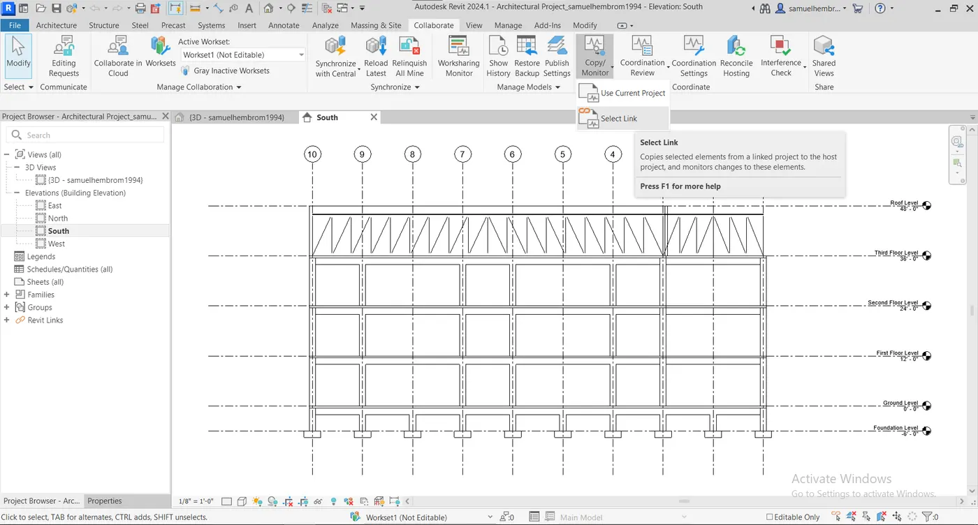
- Go to Collaborate -> Coordinate -> Copy/Monitor -> Select Link, Click on the linked file.
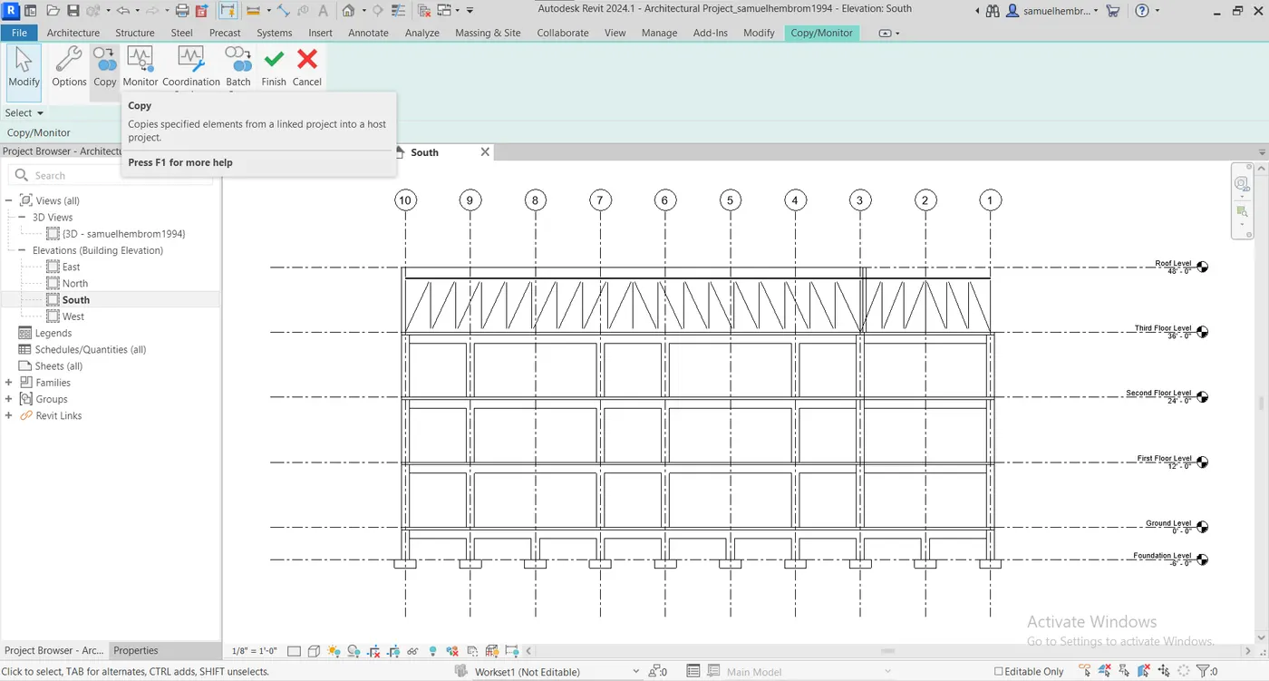
- Go to Copy/Monitor -> Tools -> Copy.
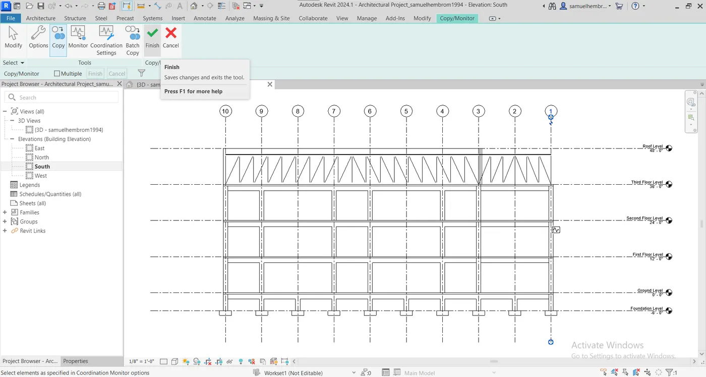
- Select the Levels and Grids one by one.
- Go to Copy/Monitor -> Copy/Monitor -> Finish.
Step - II(Creating Floor Plans):-
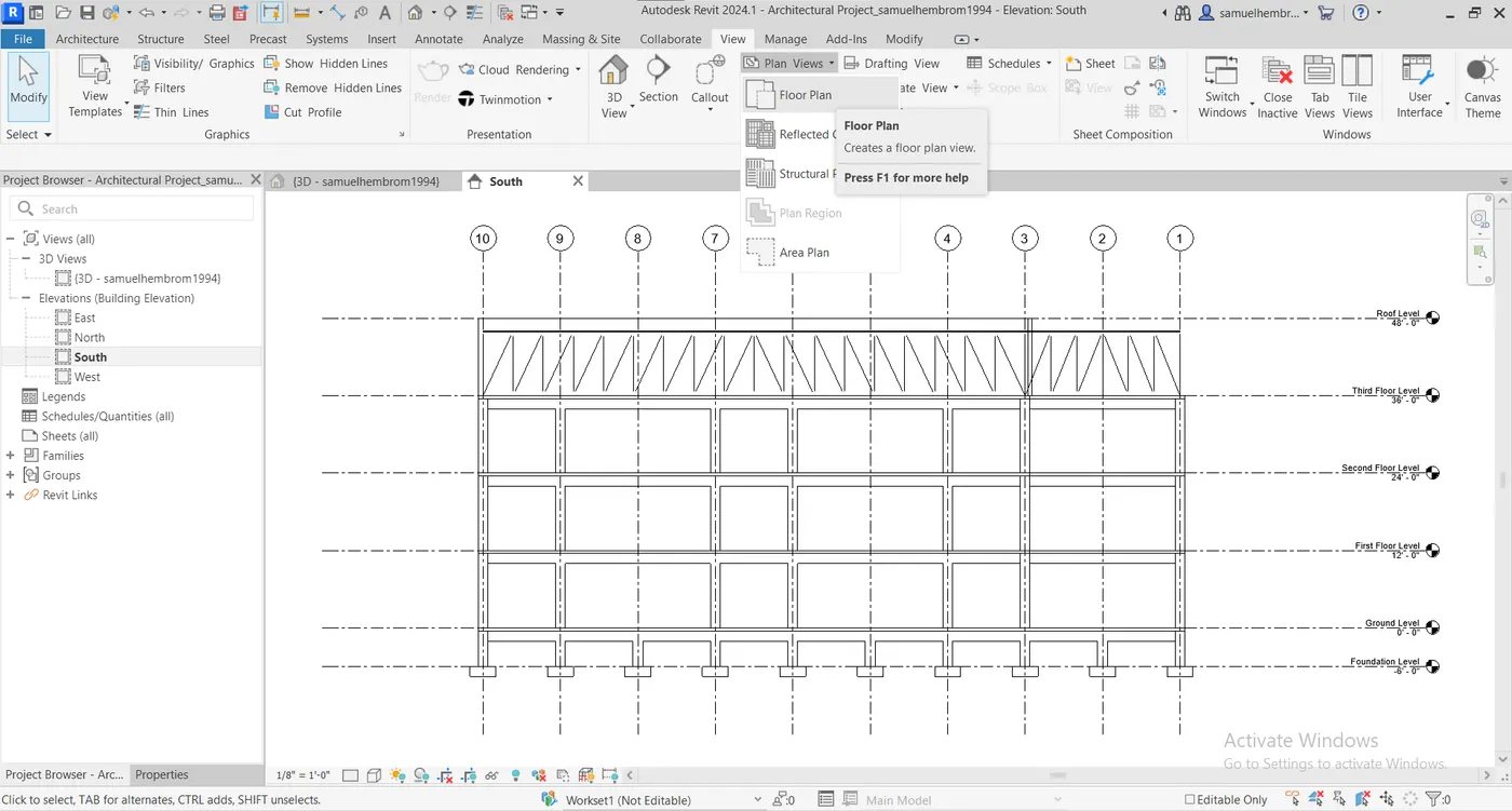
- Go to View -> Create -> Plan Views -> Floor Plan.
- From the New Floor Plan tab choose all the floor plans from Ground Floor Level to Roof Level.
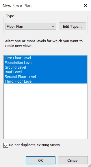
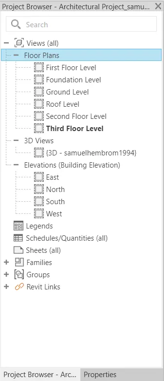
- In the project browser we can see all the plans created.
Step -III(Creating Walls on all the floors):-
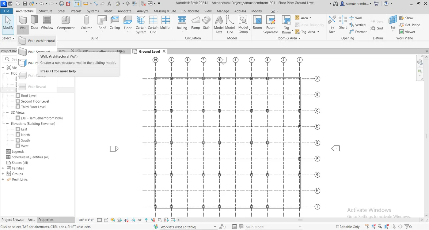
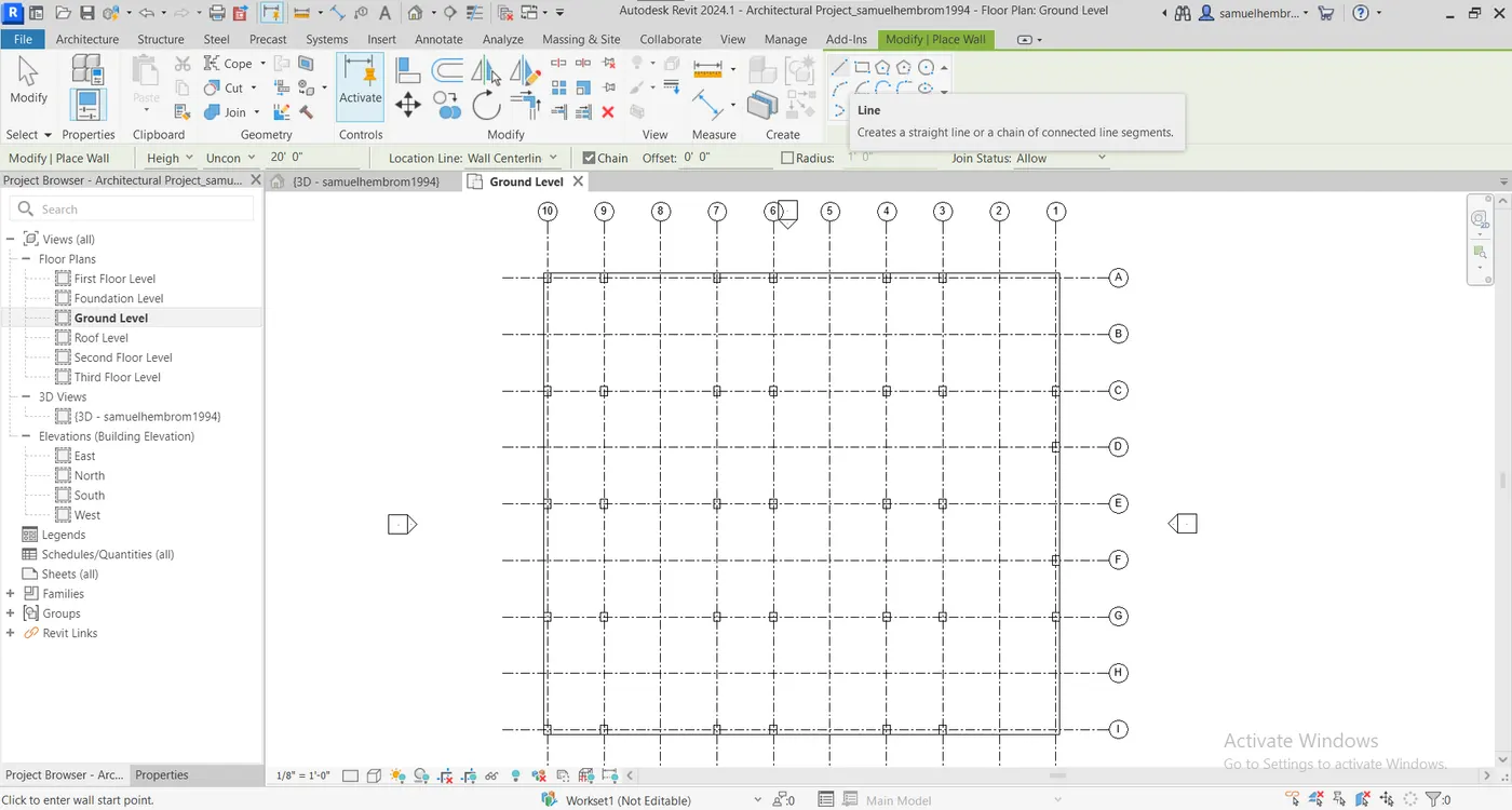
- Go to Architecture -> Build -> Wall -> Wall: Architectural.
- Go to Modify/Place Wall -> Draw -> Line.
- Draw the walls as shown in image below.
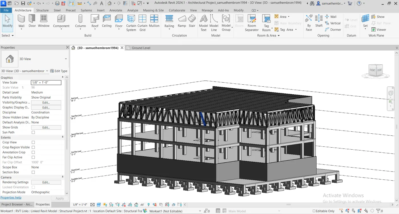
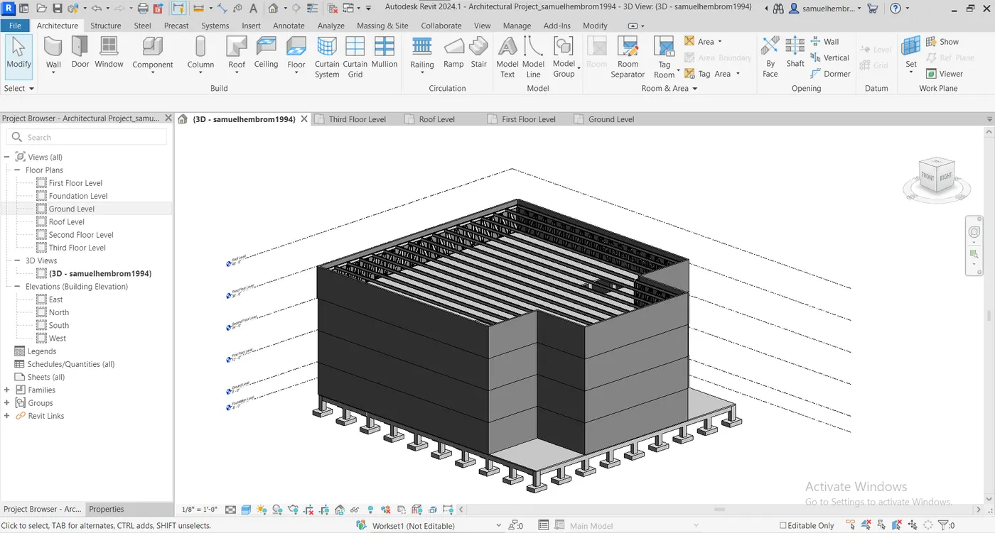
- Similarly place walls on all the floors.
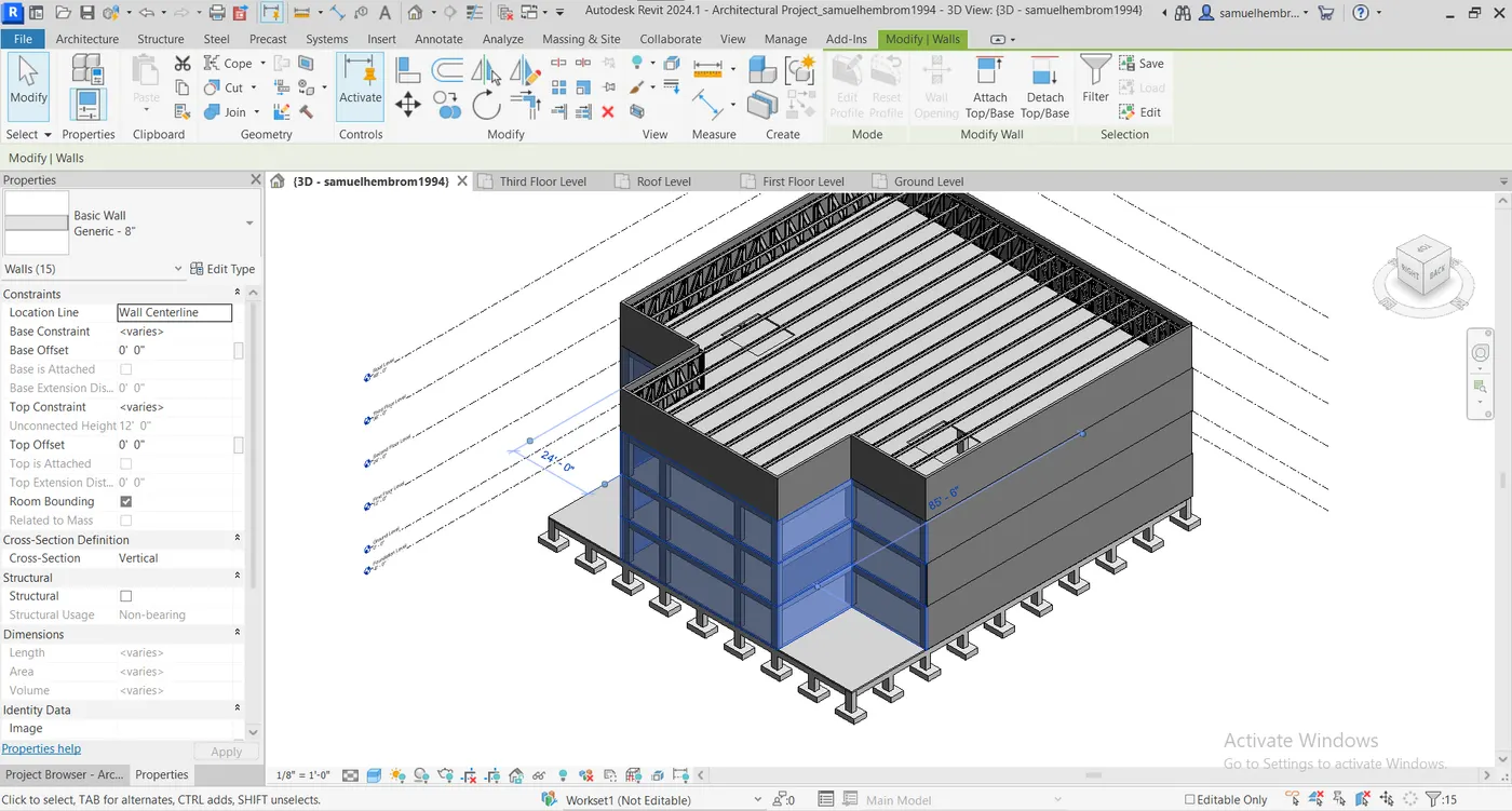
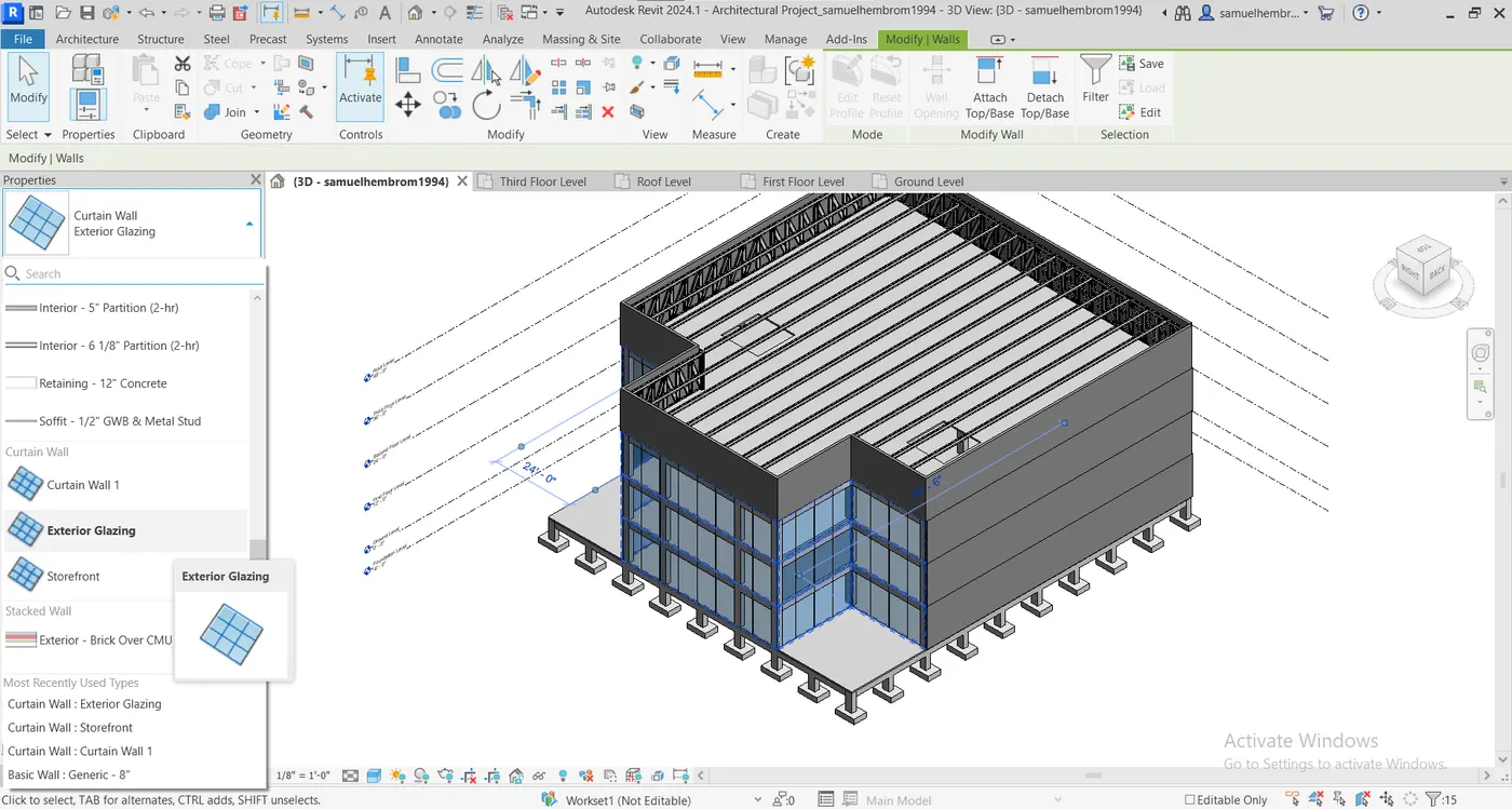
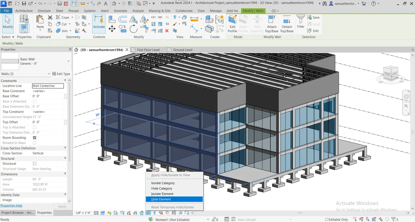
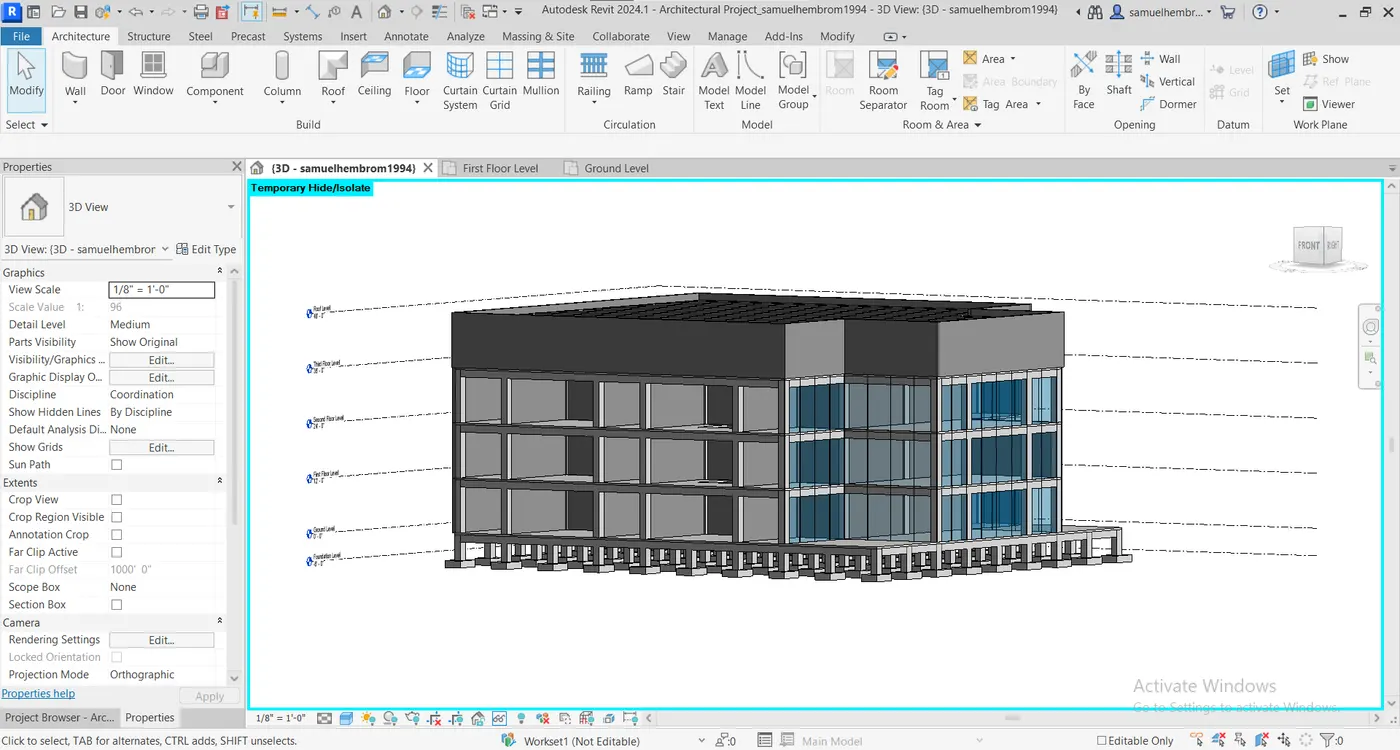
- Now select all the east facing walls and from the properties browser change the walls to exterior glazing.
Step-IV(For Interior Partition Walls):-
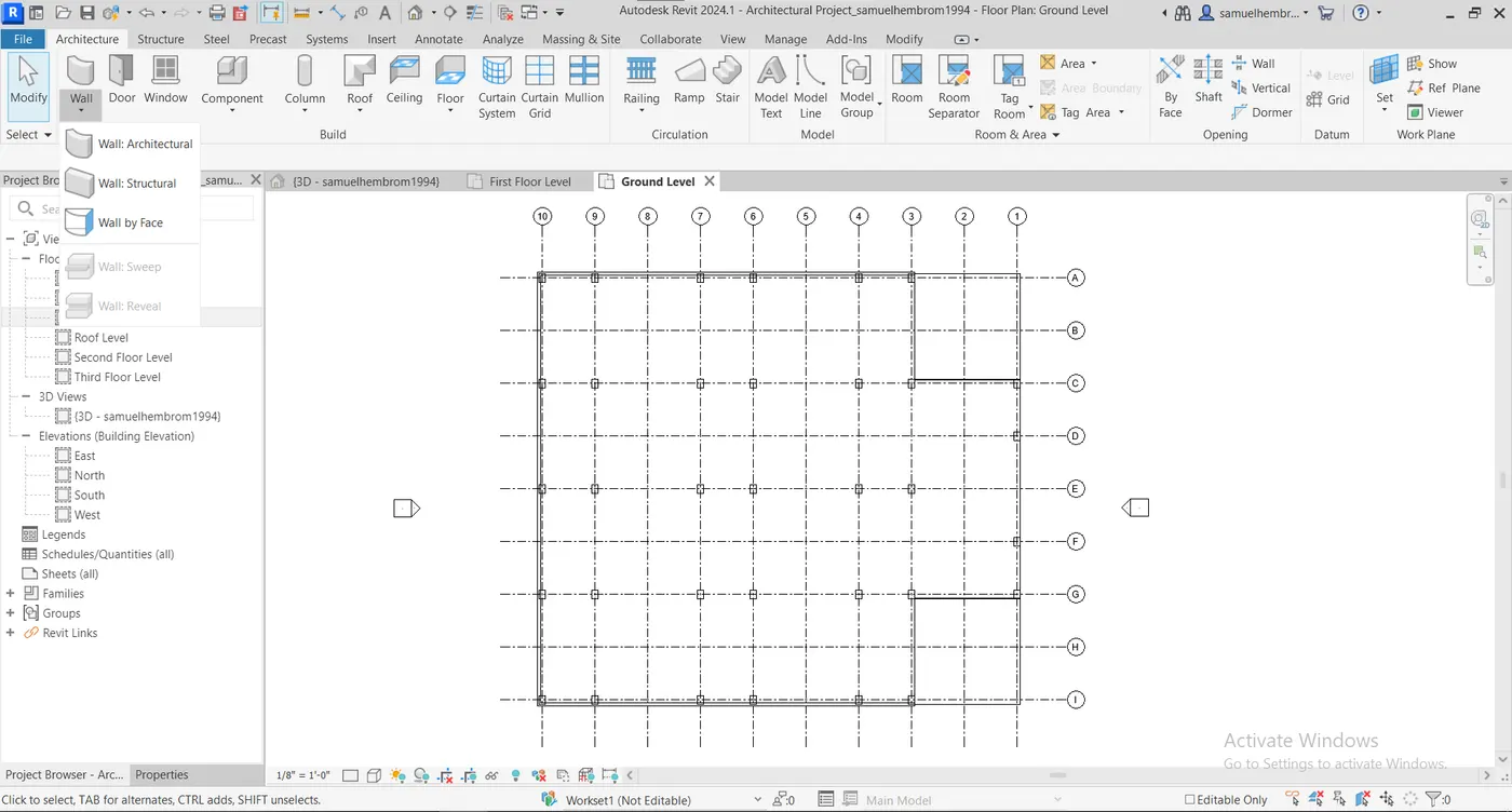
- Go to Architecture -> Build -> Wall: Architecture.
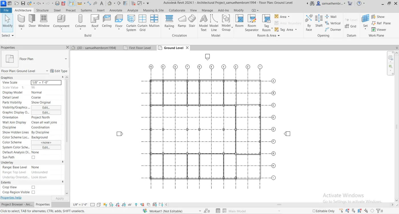
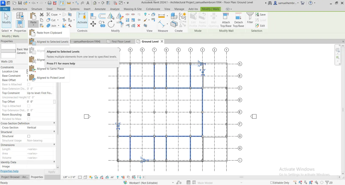
- Draw walls in the ground floor as shown in below image.
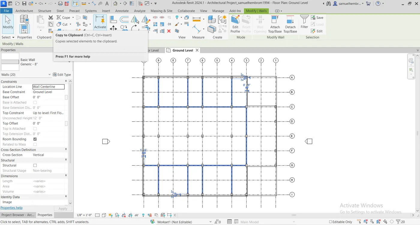
- Now select the walls and go to Modify/Walls -> Clipboard -> Copy to clipboard.
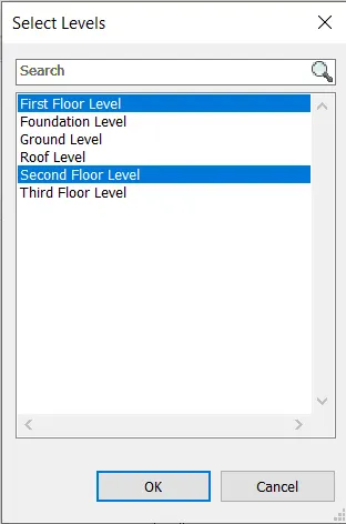
- Now go to Modify/Walls -> Paste -> Aligned to selected levels.
- Select First Floor and Second Floor Level from "Select Levels" tab.
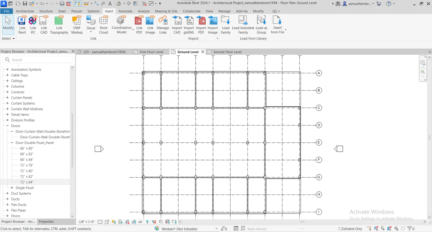
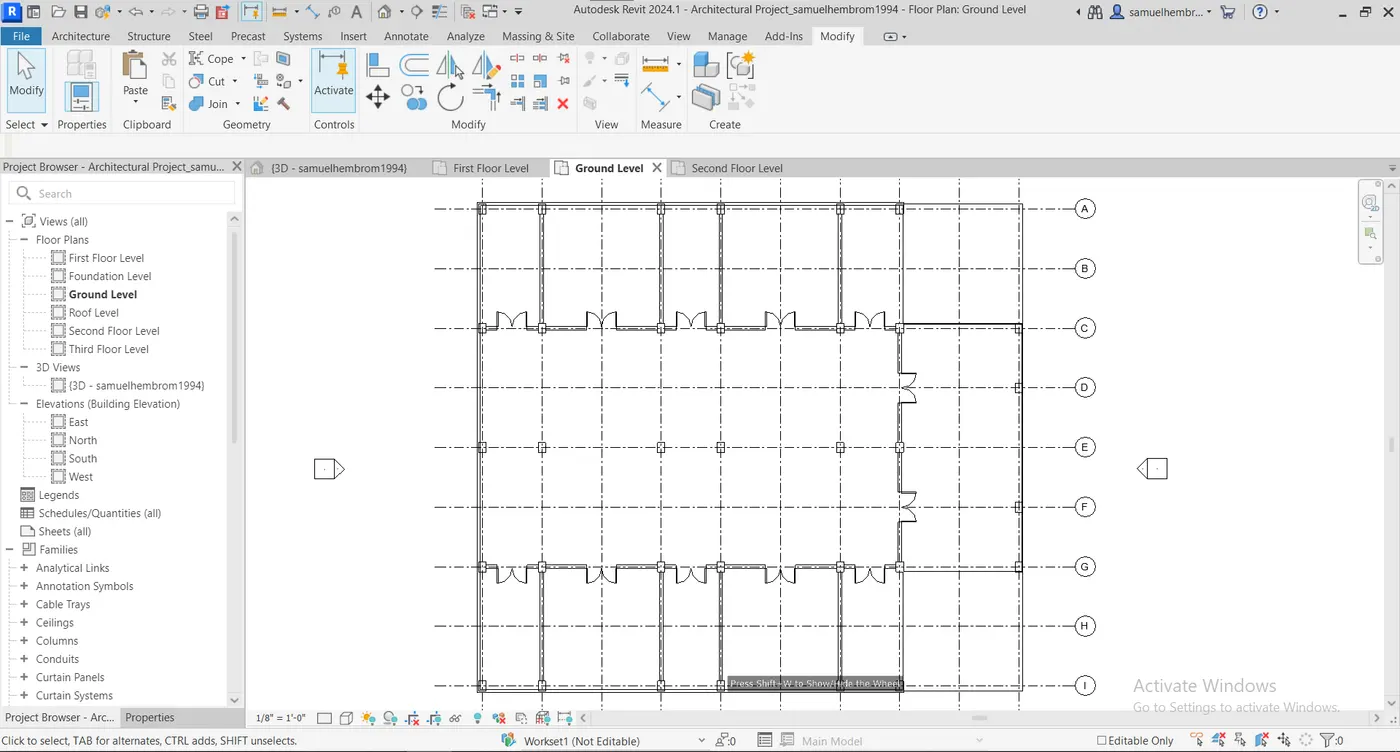
Step - V(Providing Doors):-
- Provide doors in all the floors.
- Go to Project browser under Doors section select desired door and drag it into the plan.
- Provide doors to all the floors.
Step VI(For Desk, Chair, Lighting, Plumbing Fixture):-
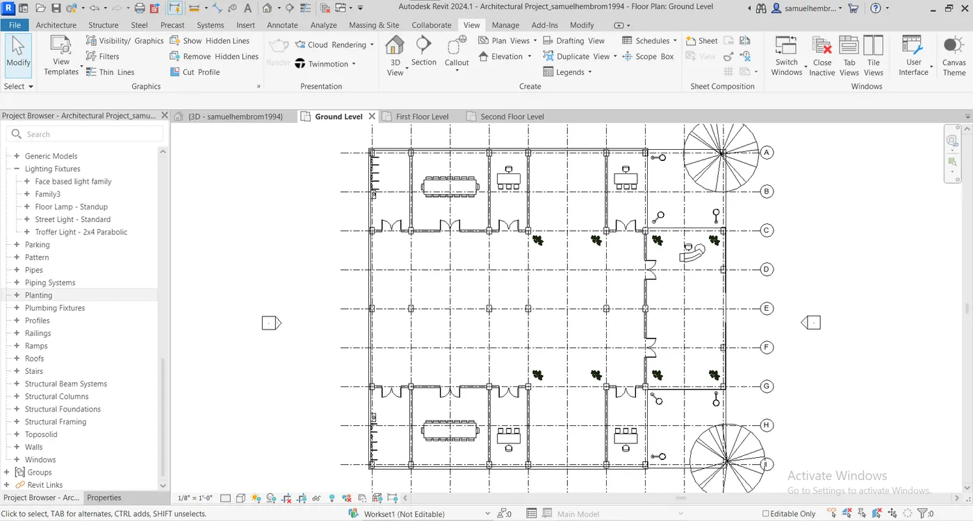
- Go to Ground Floor level plan.
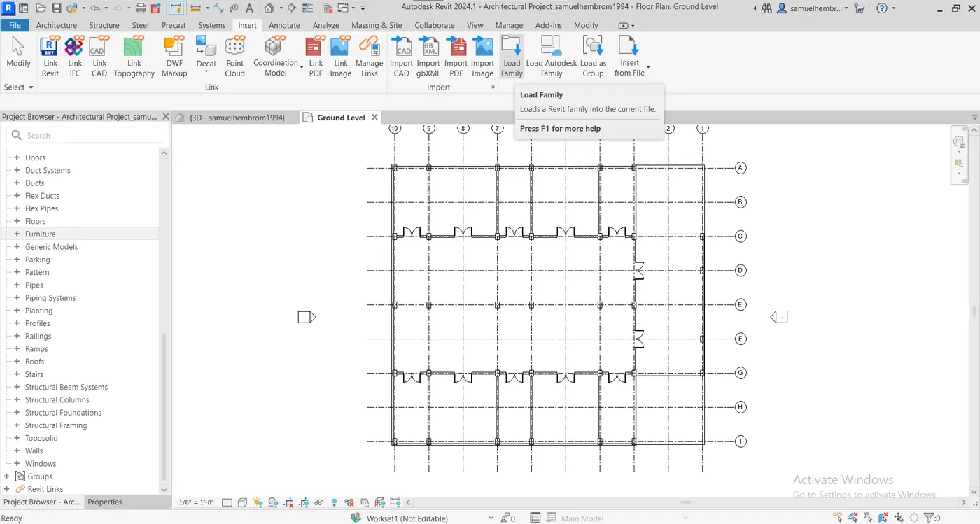
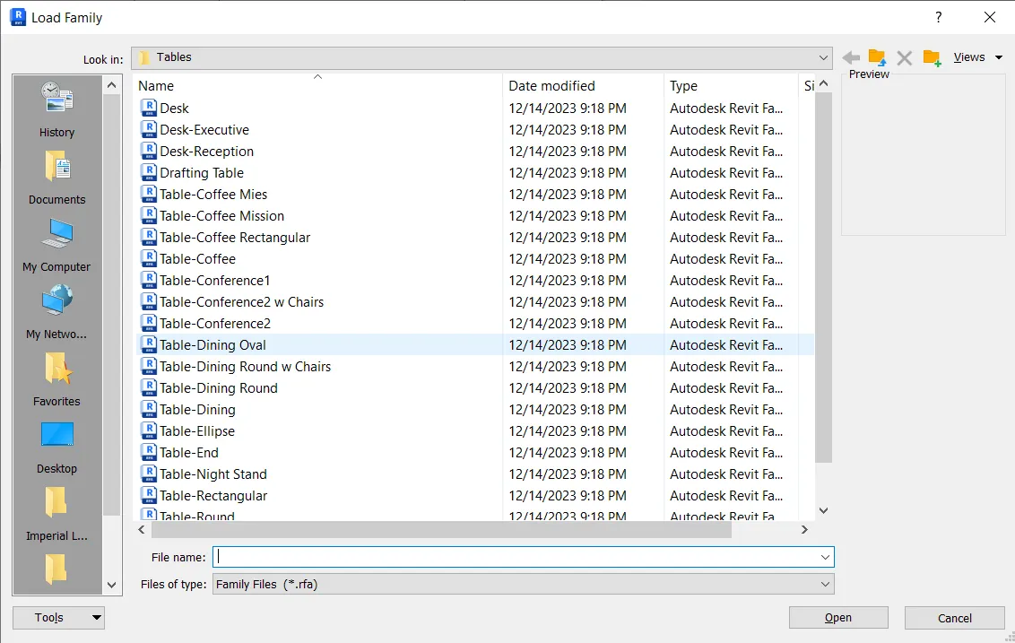
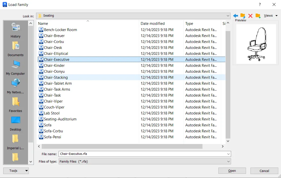
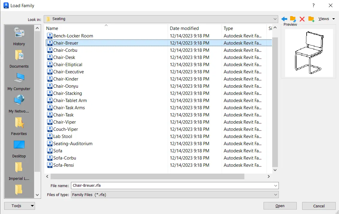
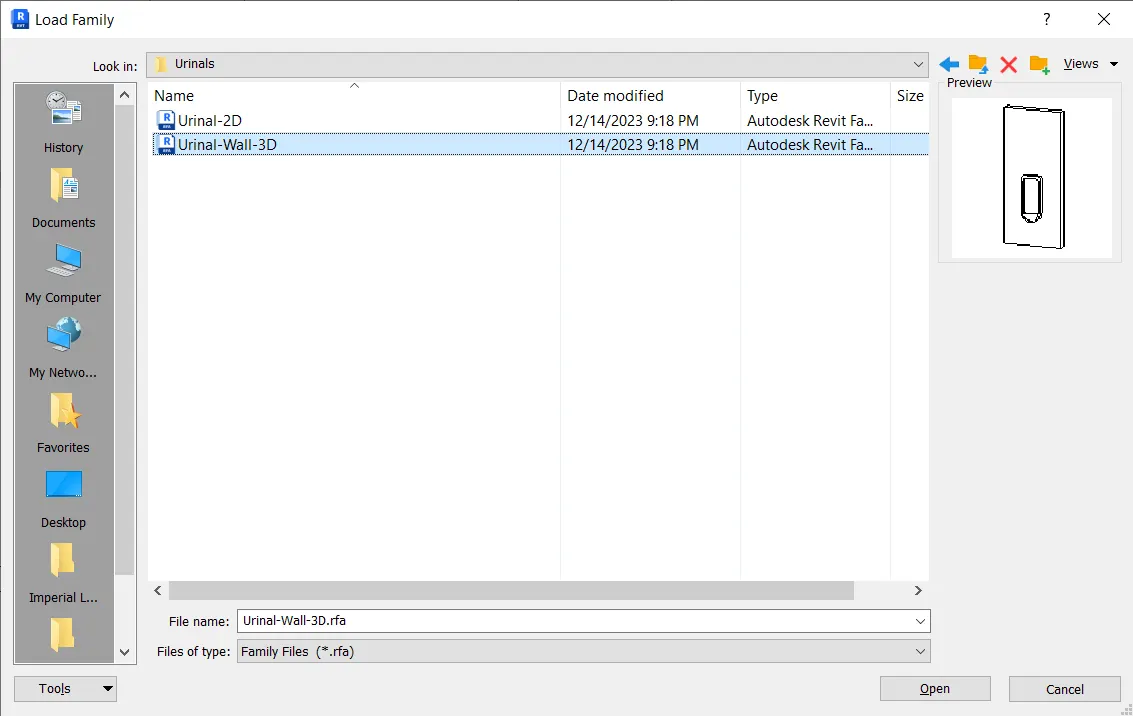
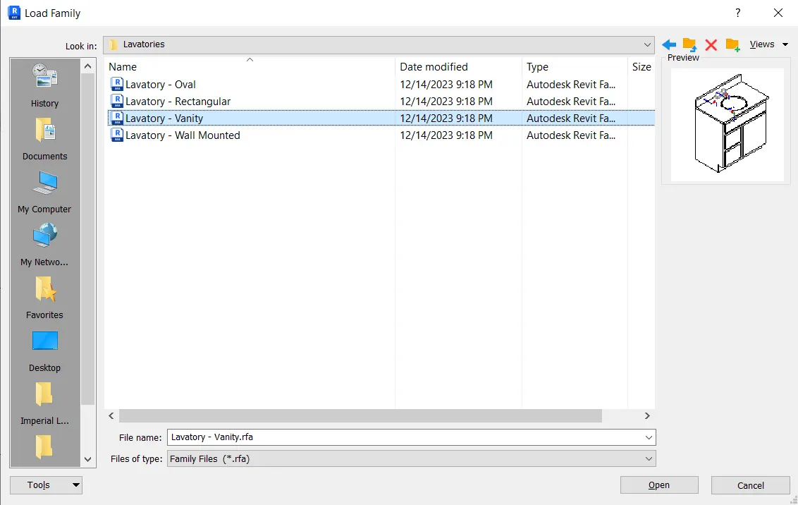
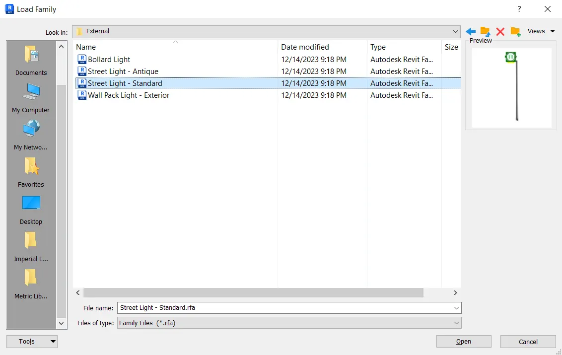
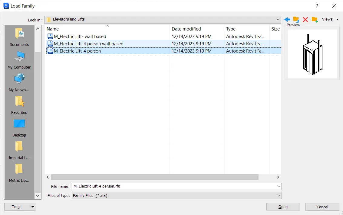
- Go to Insert -> Load From Family -> Load Family
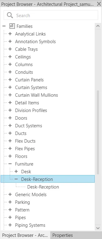
- Load the "Desk-Reception" from the Load Family box.
- In the project browser from the furniture family select the Desk-Reception and drag it to the plan.
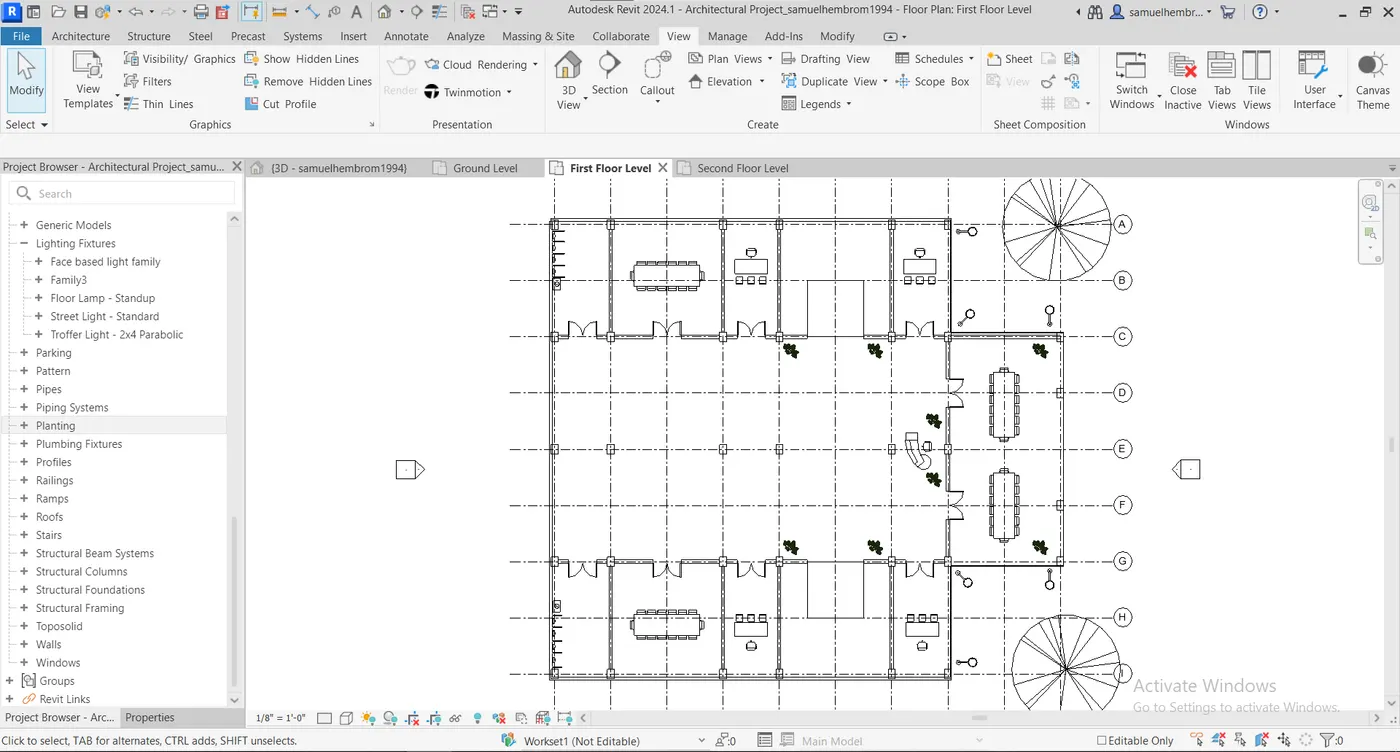
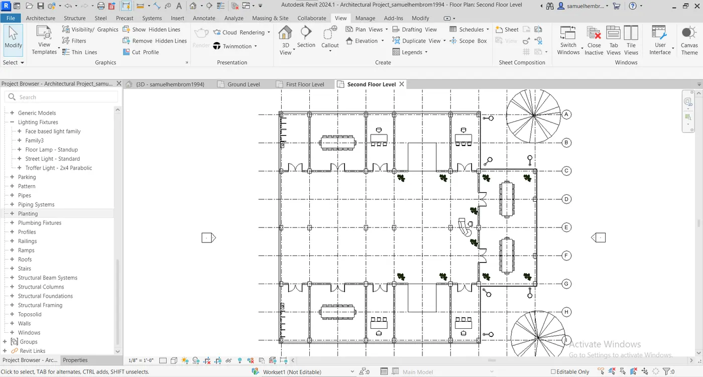
- More families are loaded as shown in below image and were dragged into the model.
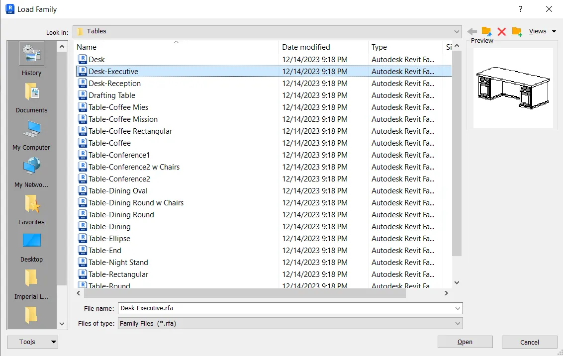
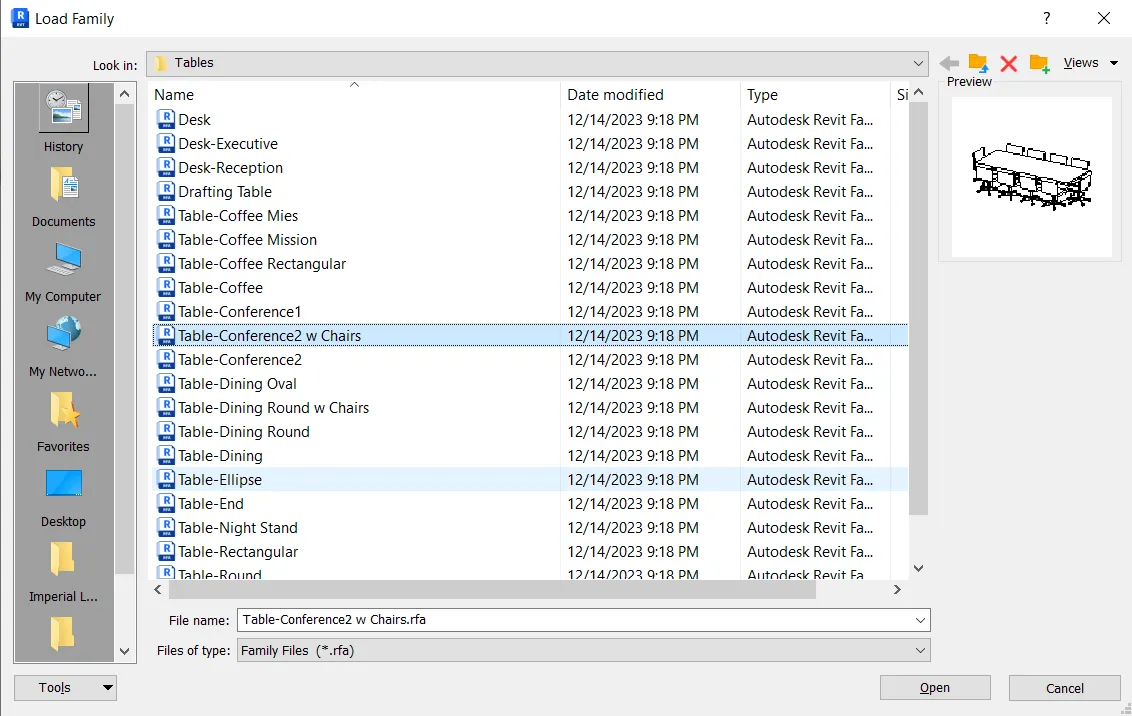
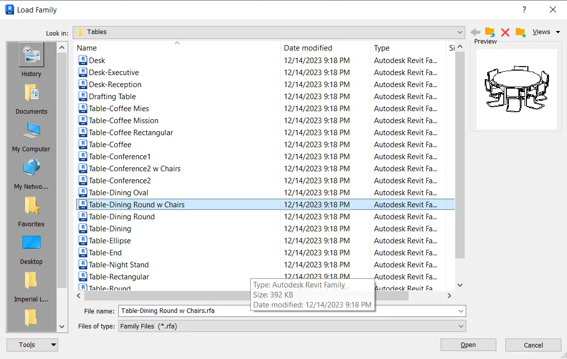
- First Floor Level:-
- Second Floor Level
- Third Floor Level
Step VII(For adding elements such as stairs and elevators):-
- Go to Insert -> Load from library -> Load Family.
- From the Load Family tab load Electric Lift-4 person.
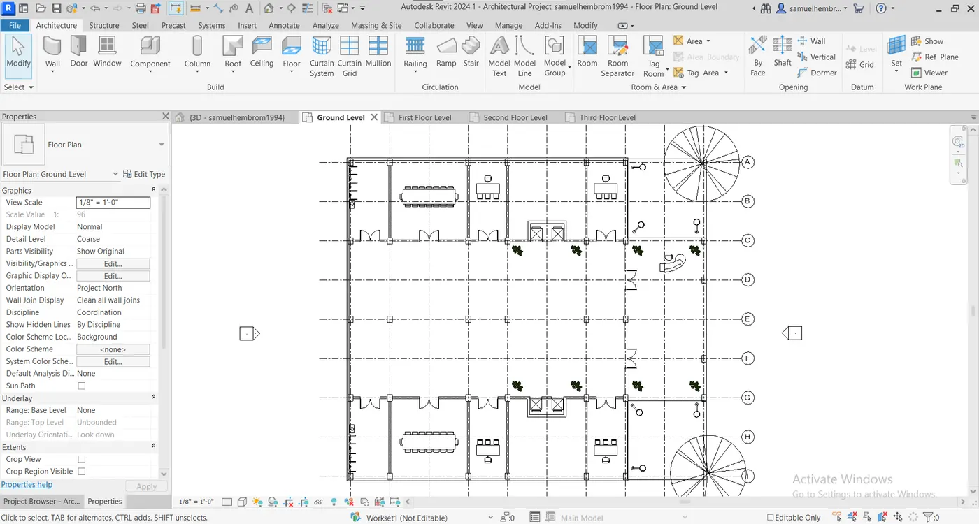
- From the project browser families drag it to the plan.
Step VII(For Parking Space):-
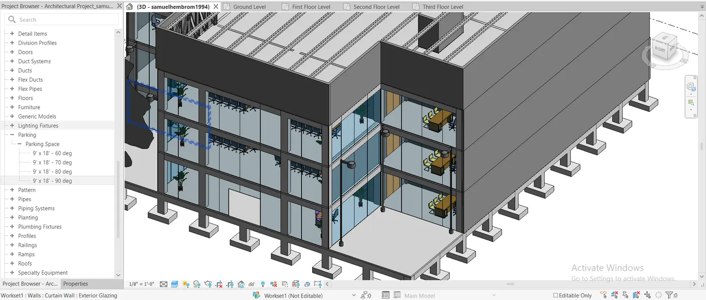
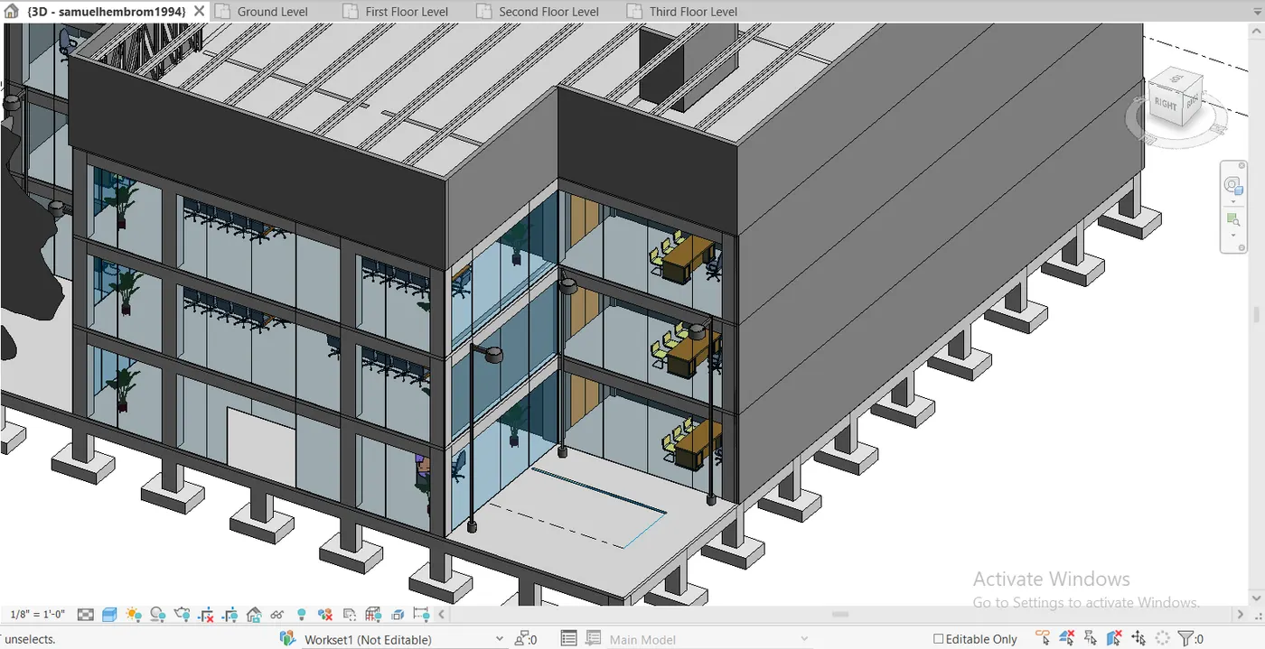
- From the parking family in project browser select 9' X 18' - 90 deg and drag it to the model as shown in below image.
Step VIII(Providing roof to the model):-
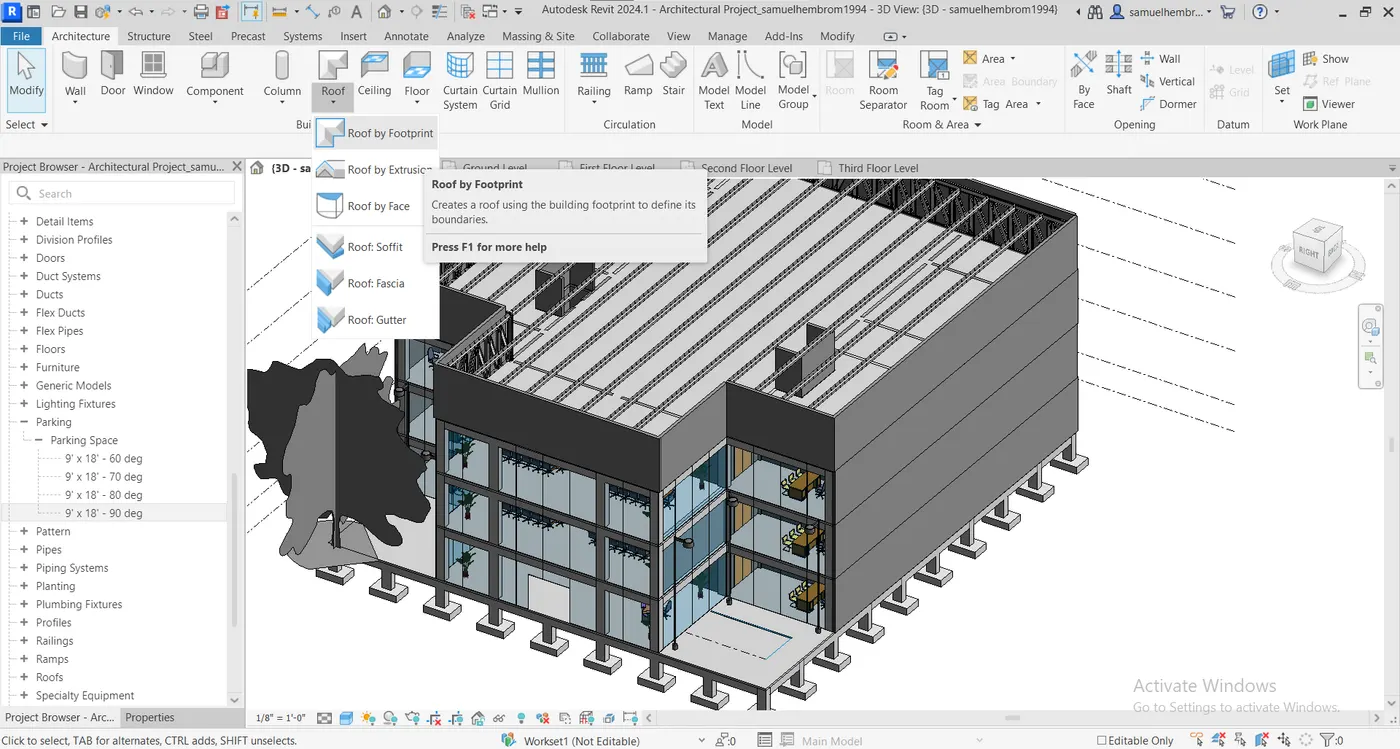
- Go to Architecture -> Build -> Roof -> Roof by footprint.
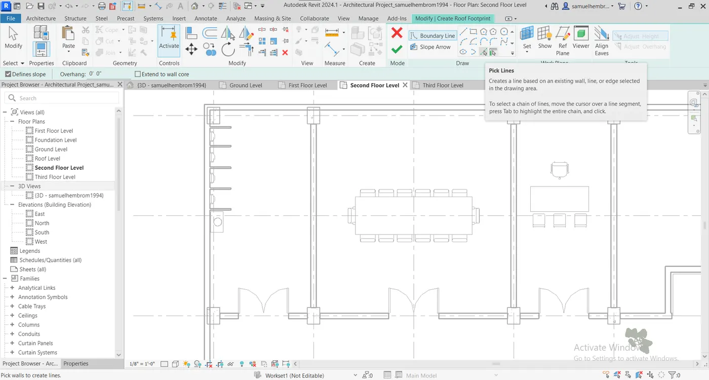
- Go to Modify -> Create Roof Footprint -> Draw -> Pick Lines or Lines option.
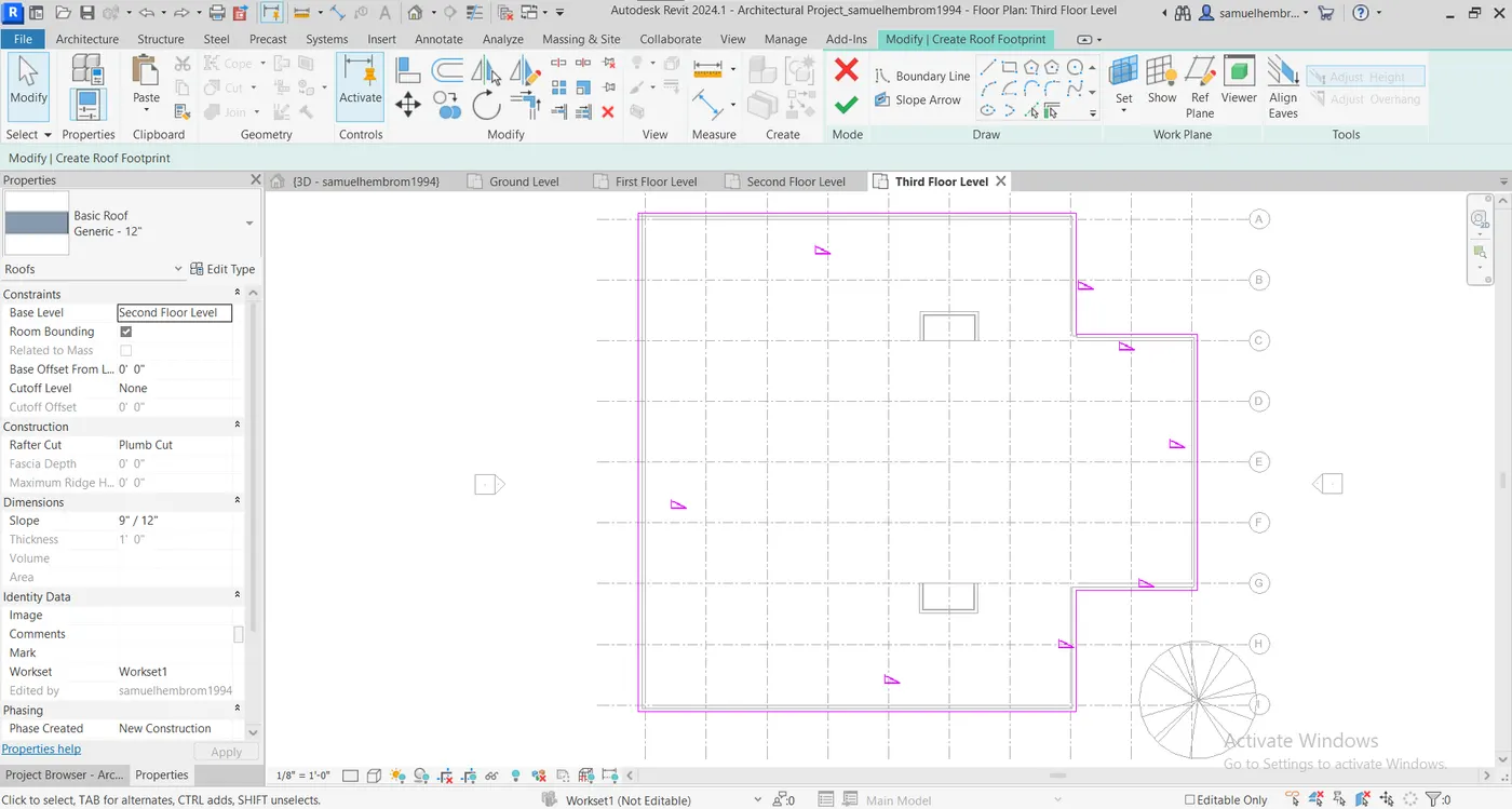
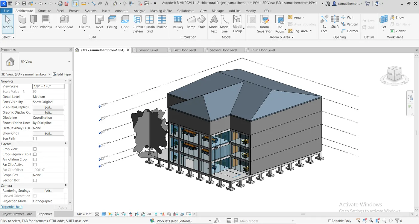
- Draw the boundary of the roof using cursor and hit finish button.
Q No 5:-
Ans:-
Aim:- To provide a set of drawings in an architectural and structural model to list the following details with categories and appropriate sheet templates floor plans, elevations, and sections.
Procedure:-
Step - I:-
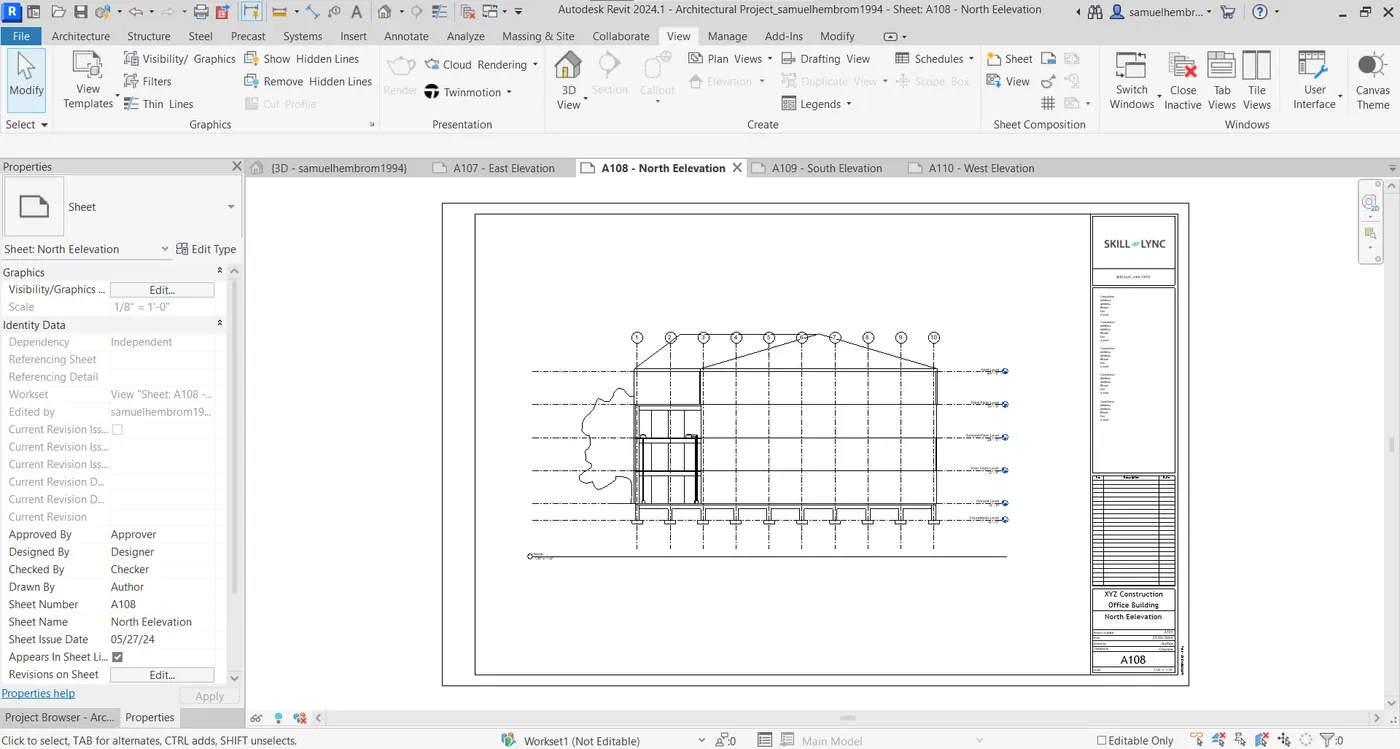
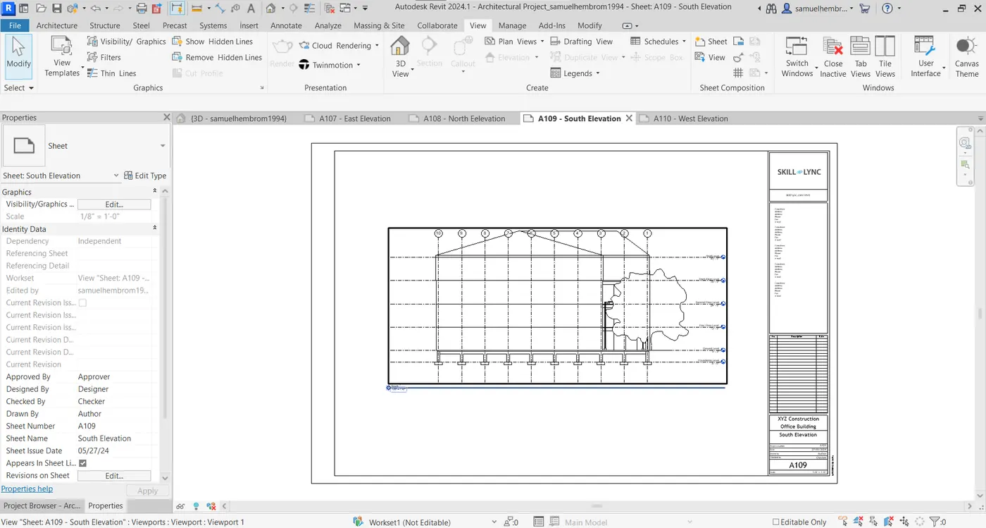
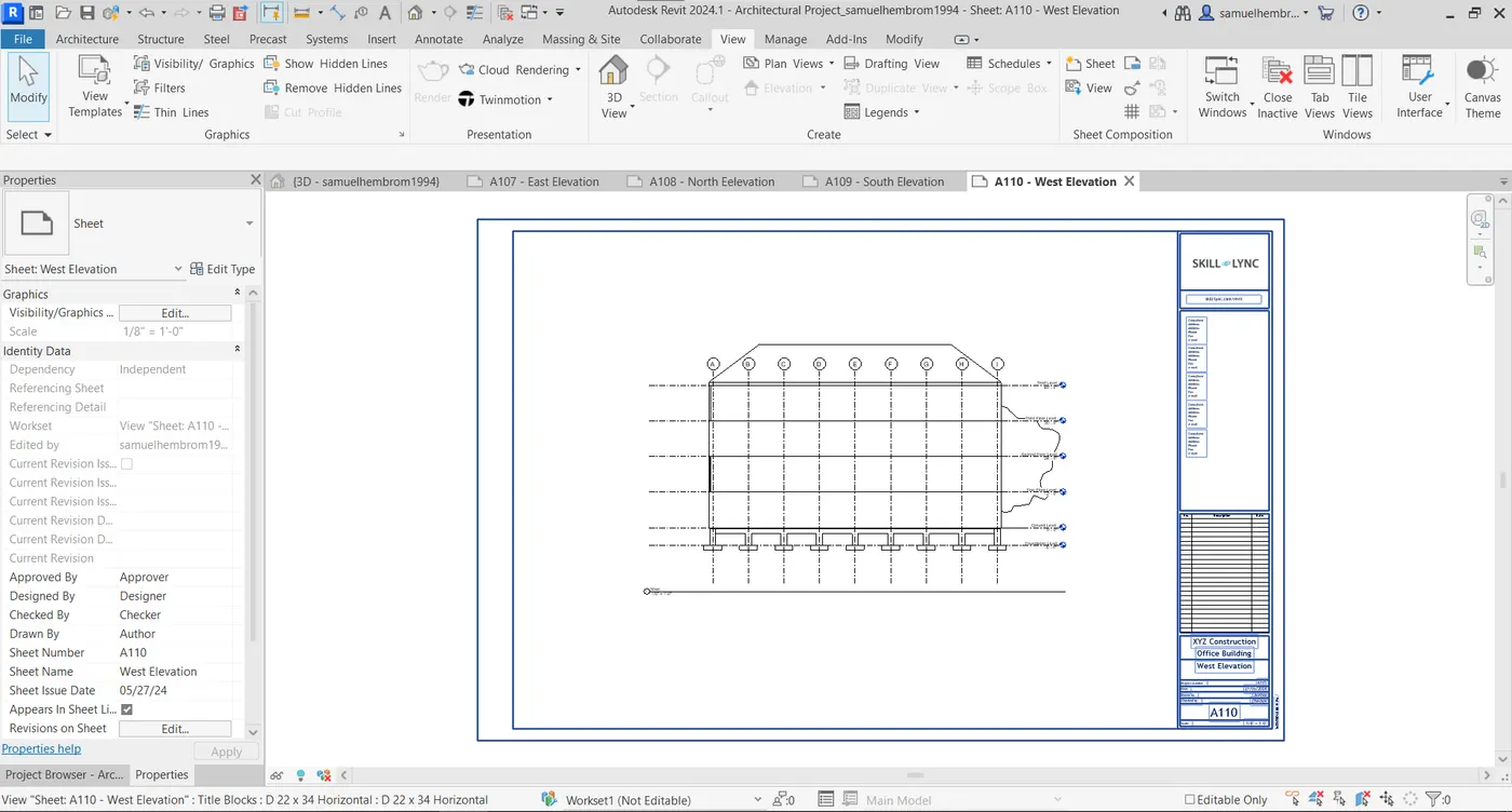
- For adding sheets go to View -> Sheet Composition -> Sheet.
- From the "New Sheet" tab click on the "Load" button and select "D 22 X 34 Horizontal".
- Specify new parameters to the sheet such as owner name, issue date, sheet number etc.
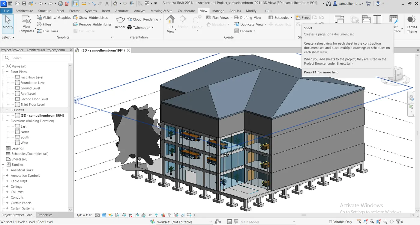
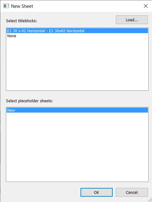
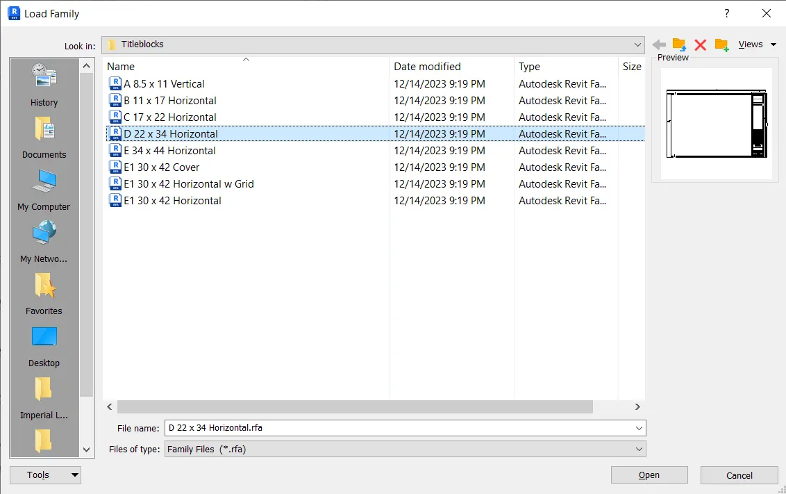
- Double click on the sheet to edit the sheet and load the project using modify tools.
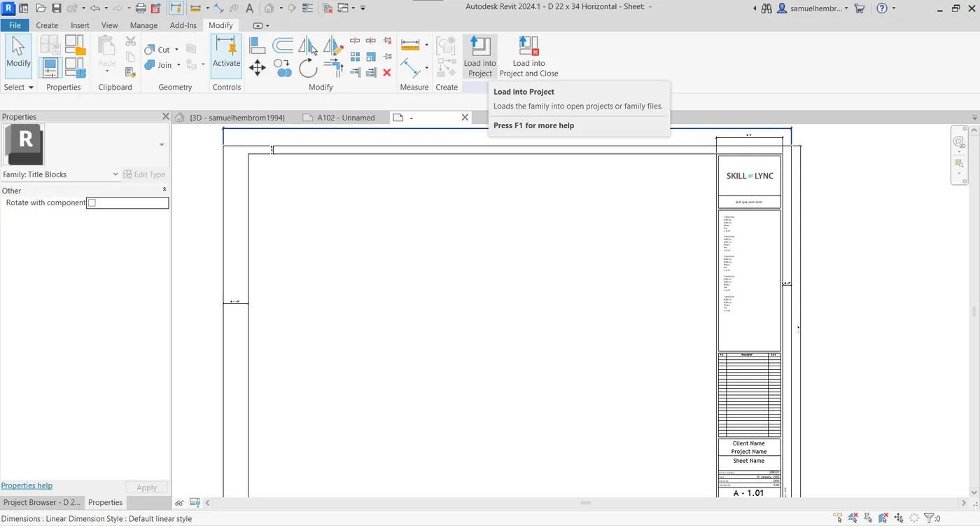
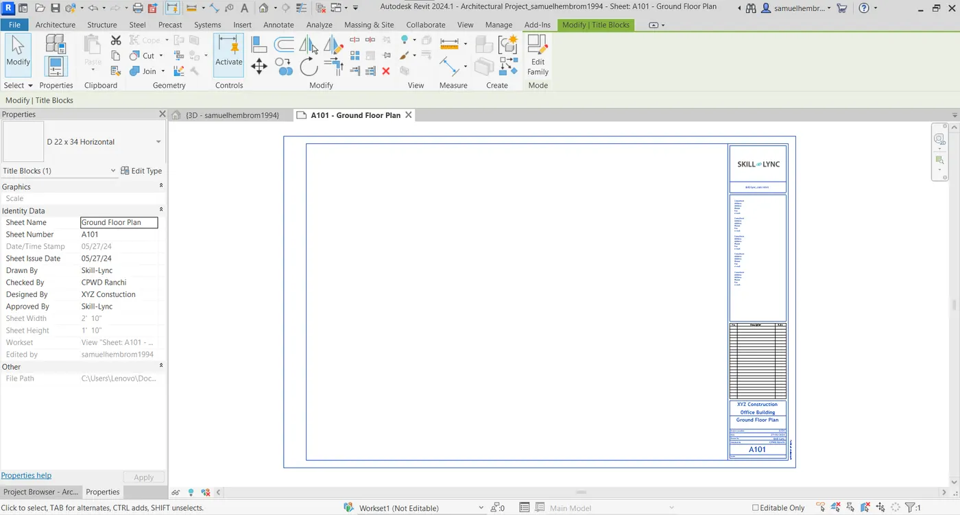
- From the project browser drag the ground floor plan into the sheet.
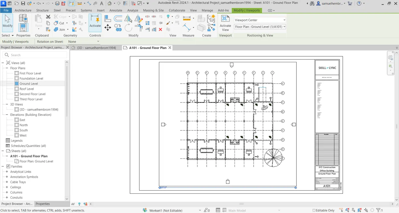
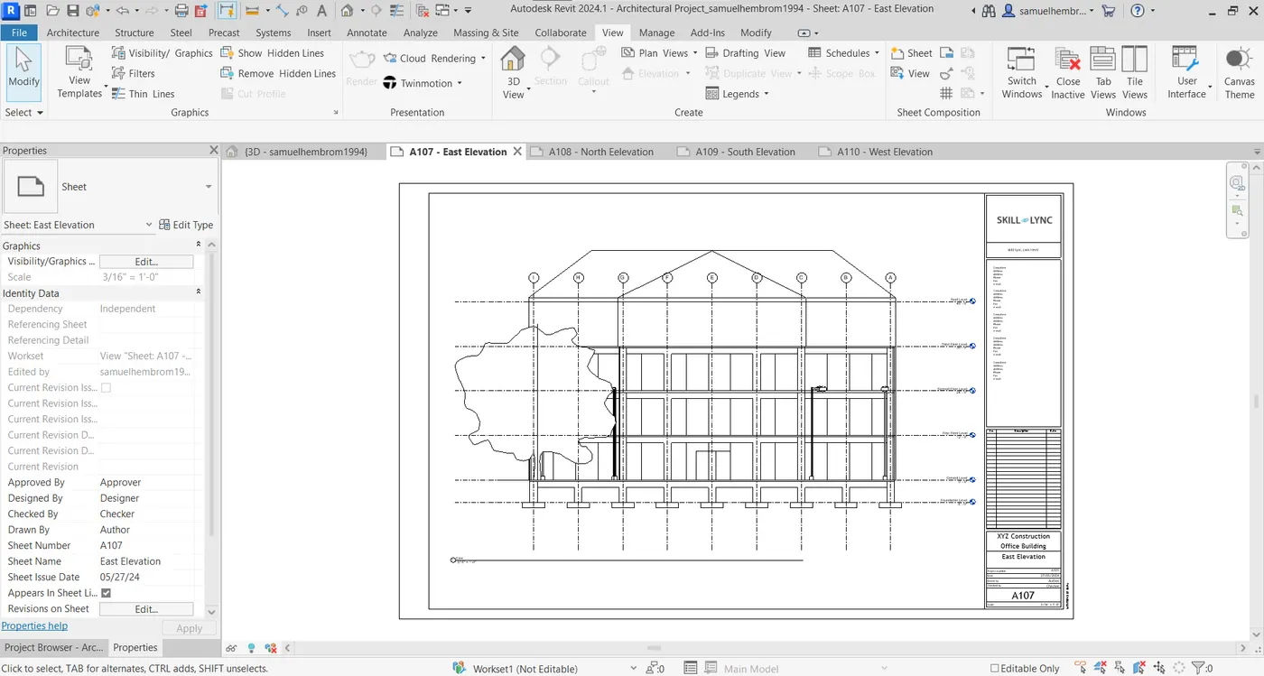
- Repeat the above process for creating sheets for other floor plans, elevation and sections.
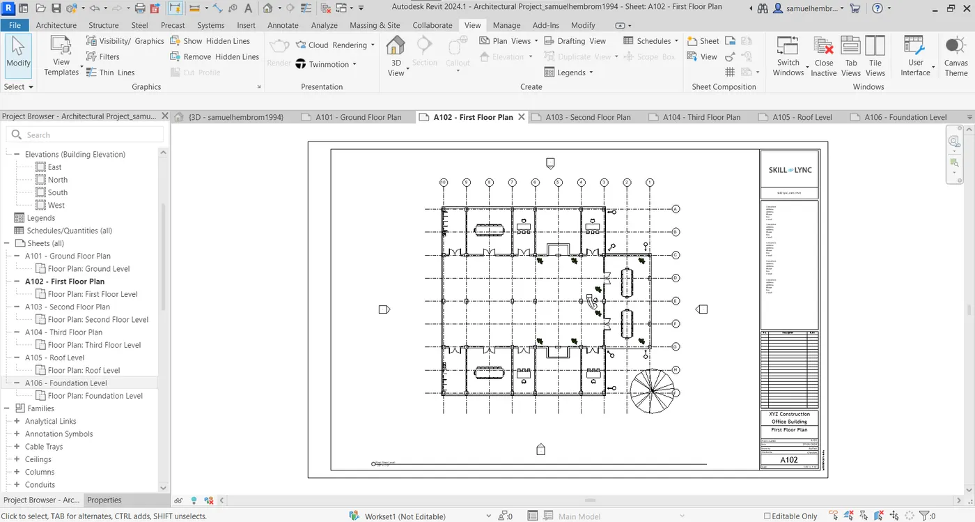
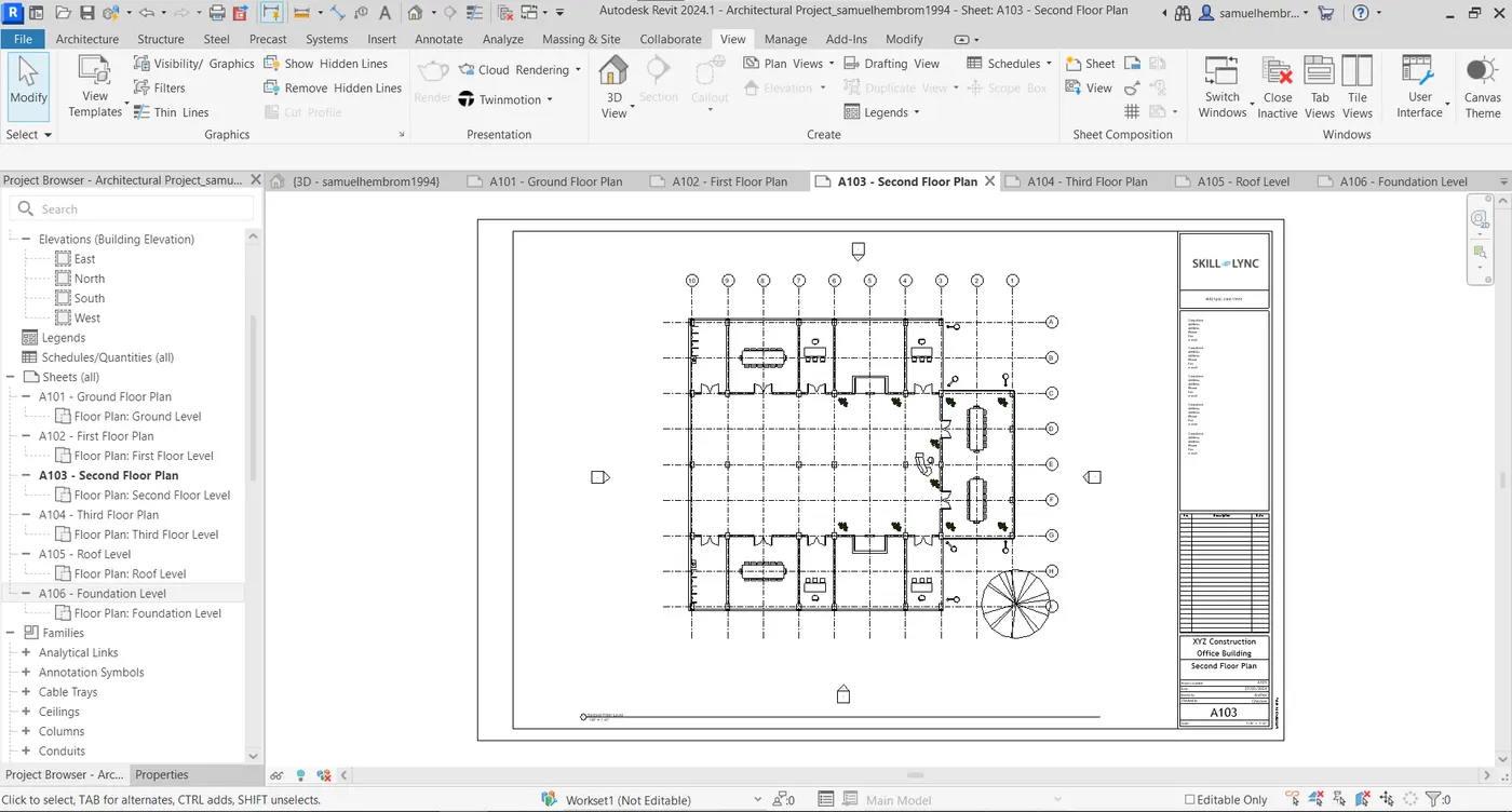
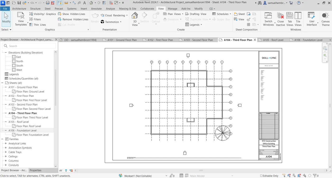
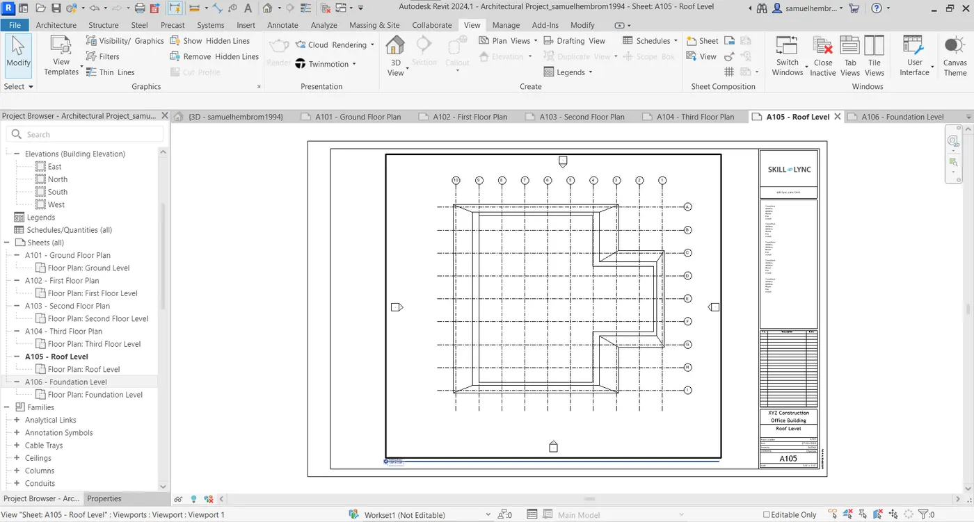
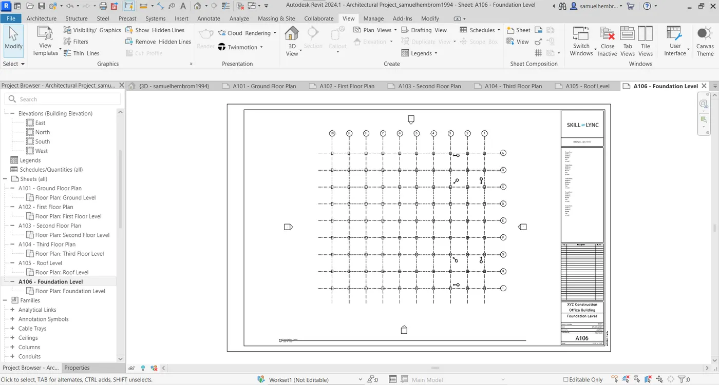
- Elevation Sheets
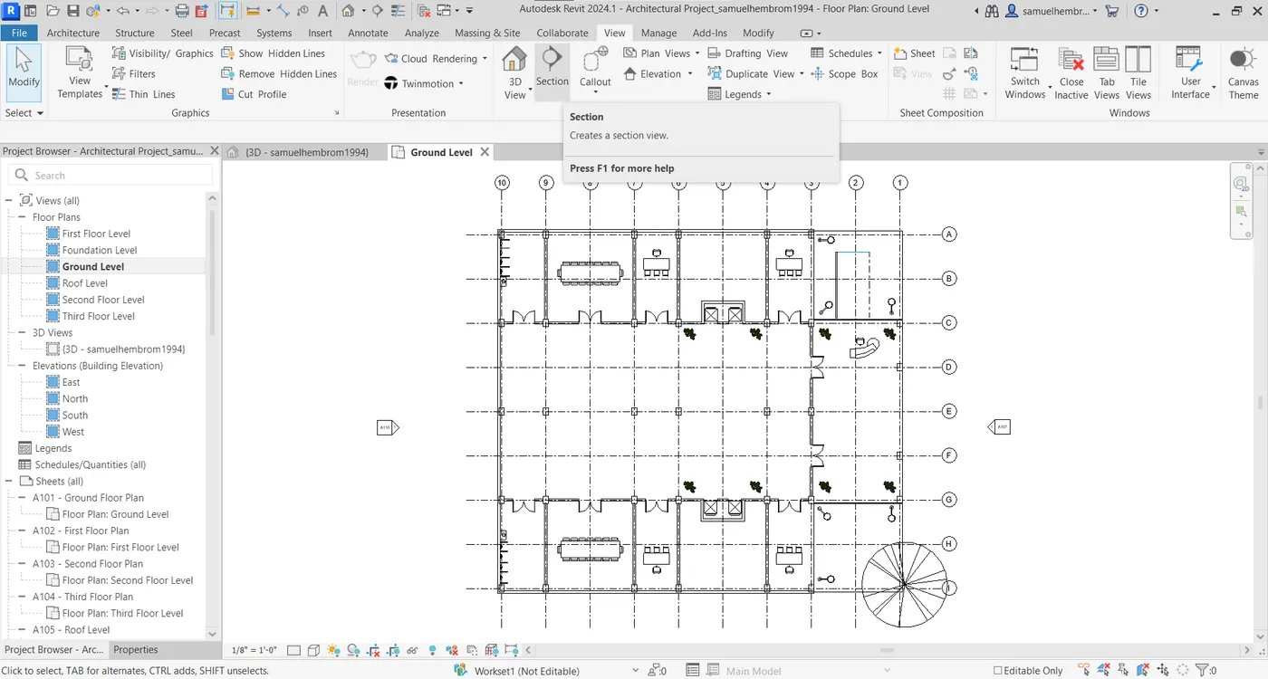
- For creating section views.
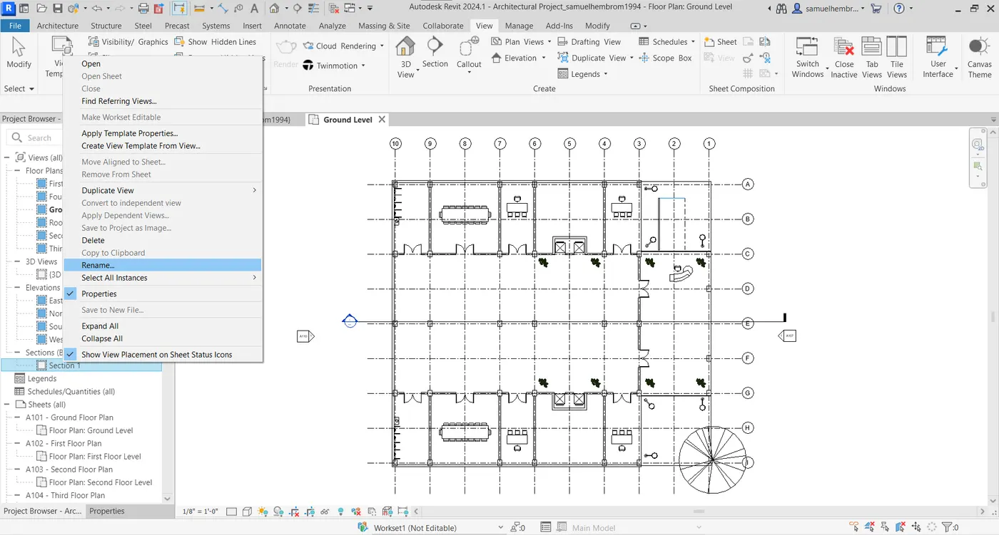
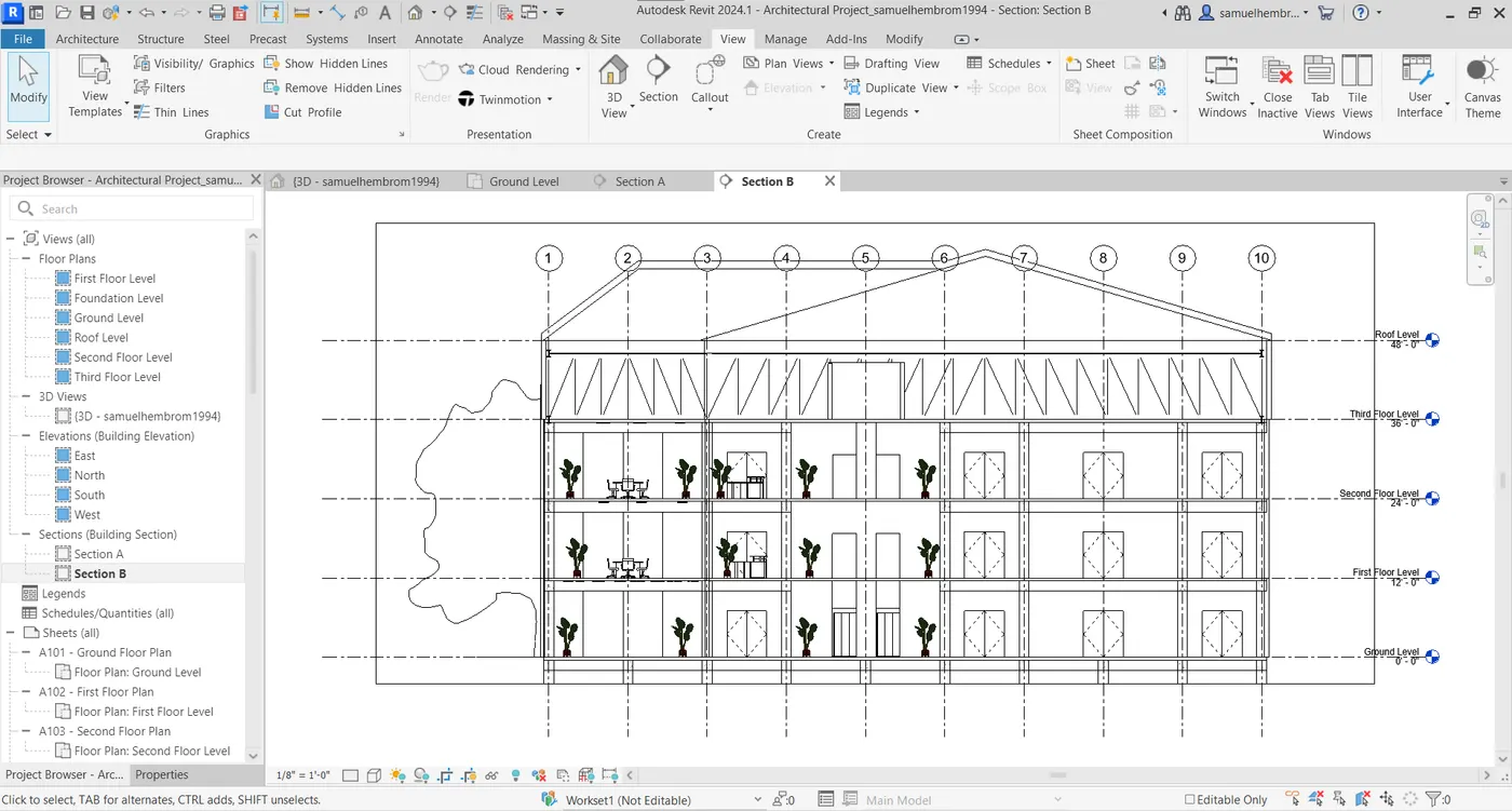
- Go to View -> Create -> Section.
- Create two sections and name them as "Section A" and "Section B".
Step - II(For providing materials to the walls):-
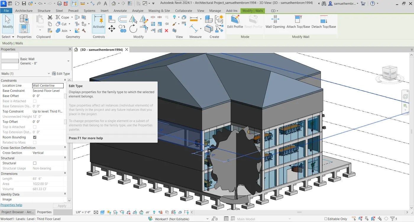
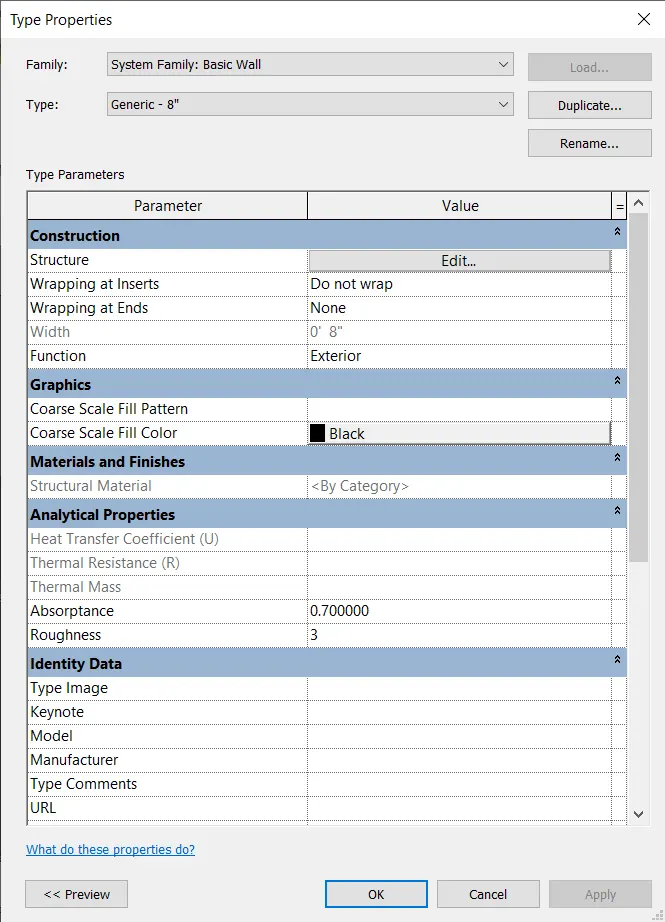
- Select a wall and go to properties browser and click on "Edit Type" button.
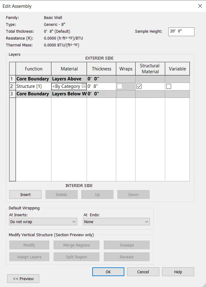
- In the "Type Properties" tab click on "Edit" button next to "Structure" parameter.
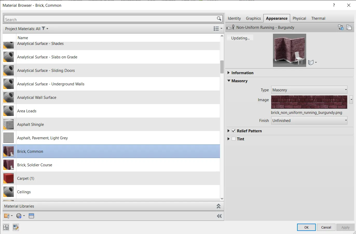
- In the "Edit Assembly" tab click on three dot button under materials category next to "Structure" function.
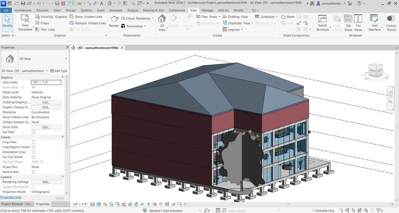
- I have selected "Brick, Common" from the "Material Browser" tab.
Q No VI:-
Aim:- To using the rendering settings, render images of the 3D model produced and include the rendered images to the drawing sheets.
Procedure:-
Step-I(For creating camera view)
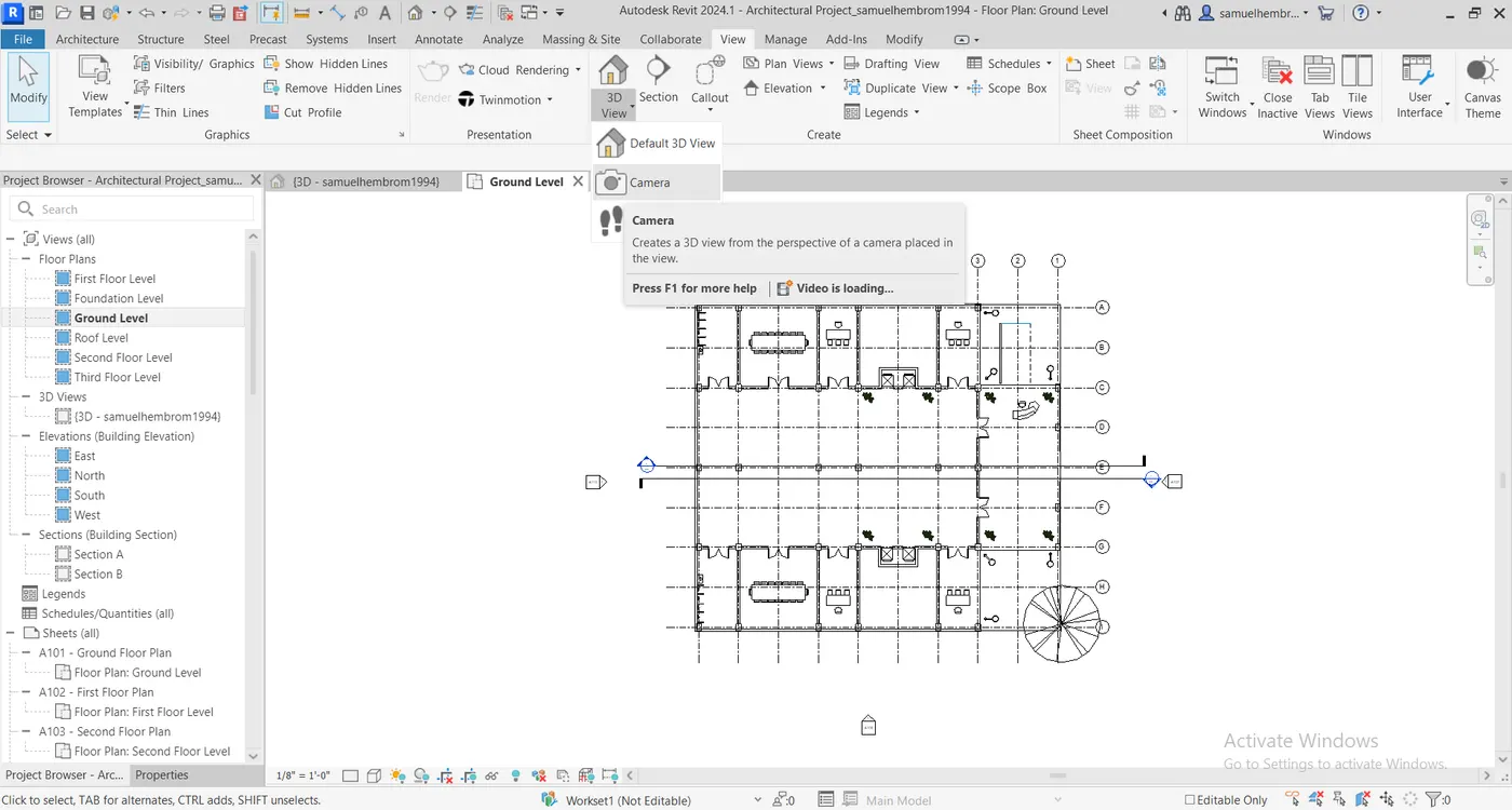
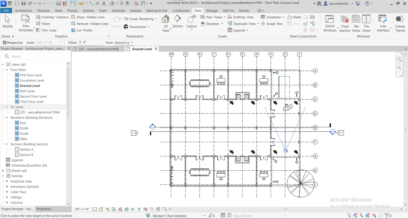
- Go to View -> Create -> 3D View -> Camera
- Use the cursor to place the camera.
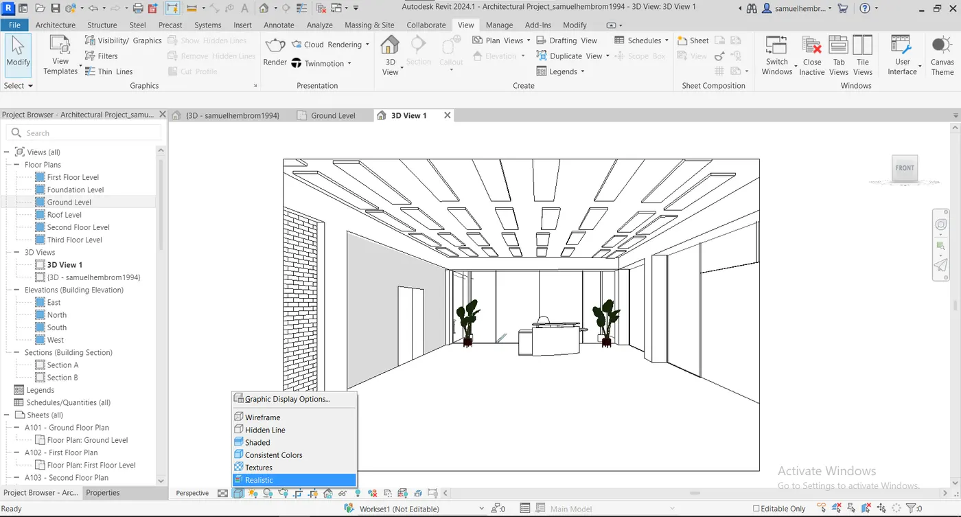
- Change the perspective to Realistic in the camera view.
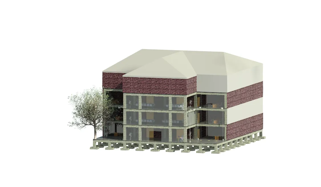
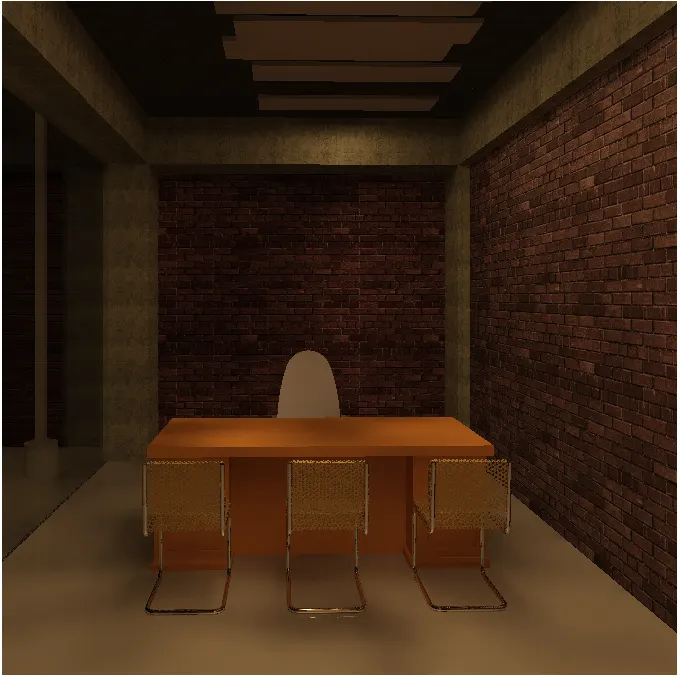
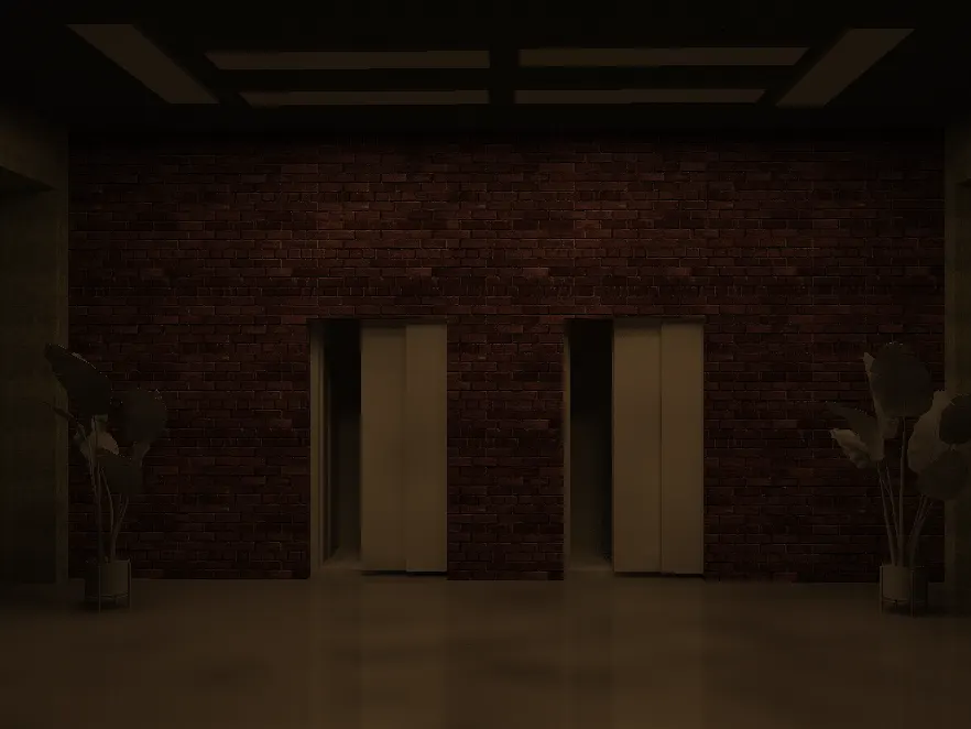
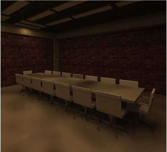
Step -II(For Creating Rendered View):-
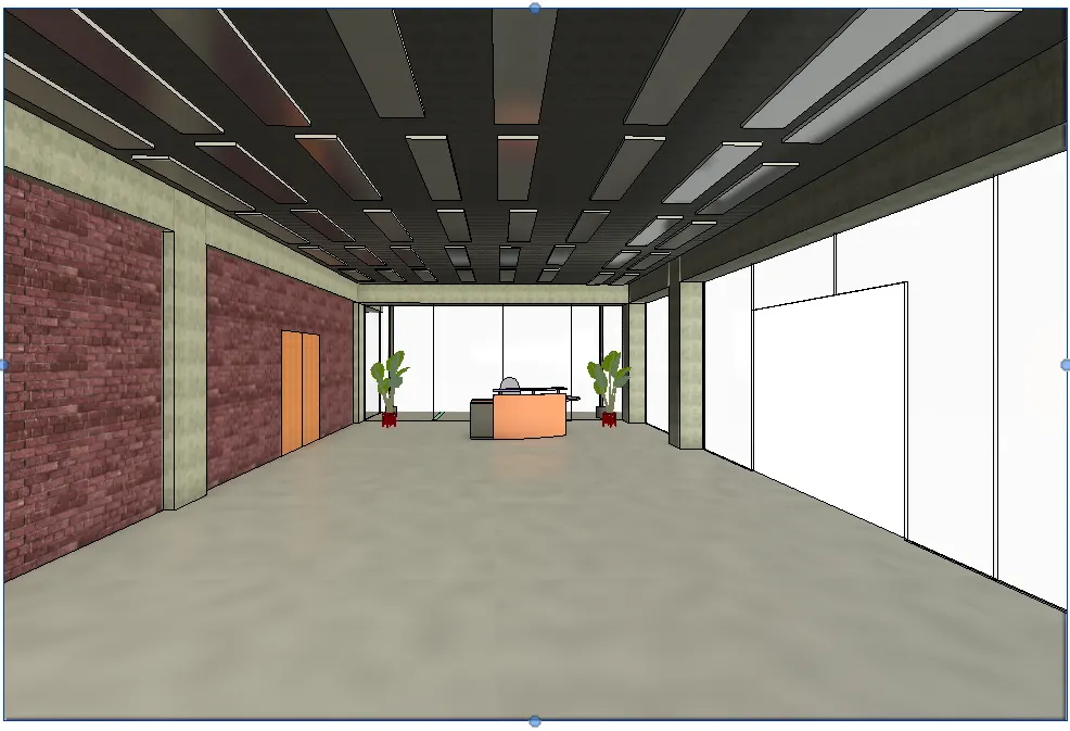
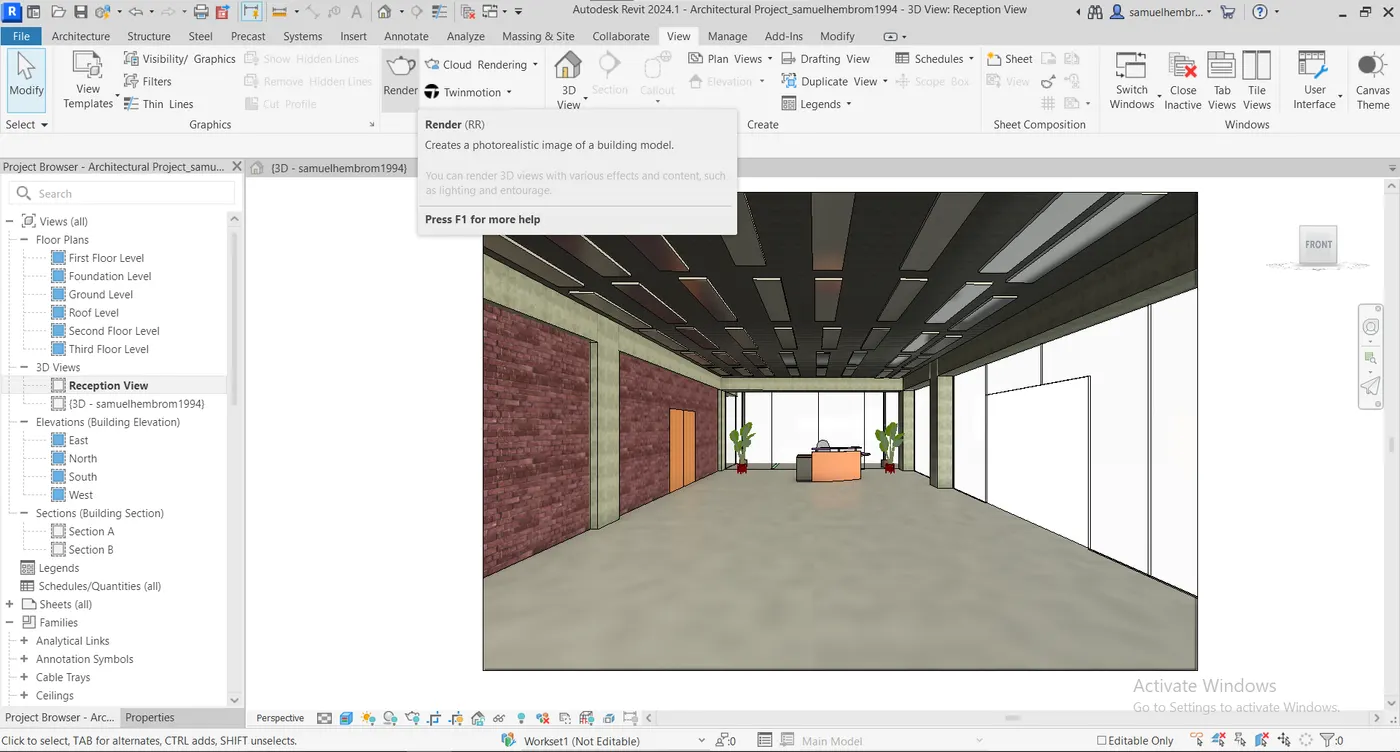
- Go to View -> Presentation -> Render.
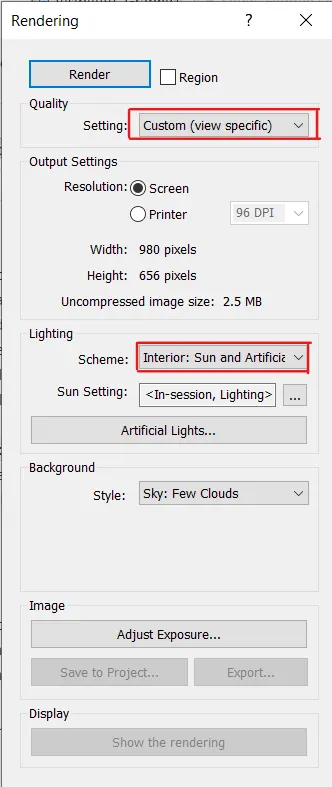
- From the "Rendering" tab I have selected "Custom (view specific)" as quality settings and "Interior: Sun and Artificial" as lighting scheme.
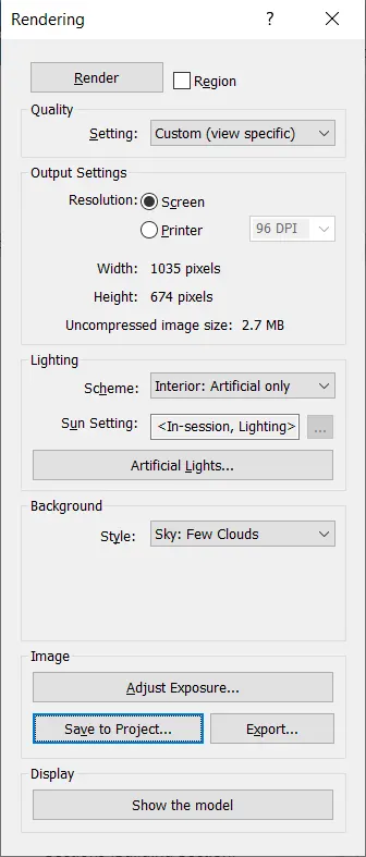
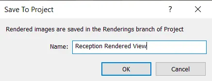
- Save the rendered views.
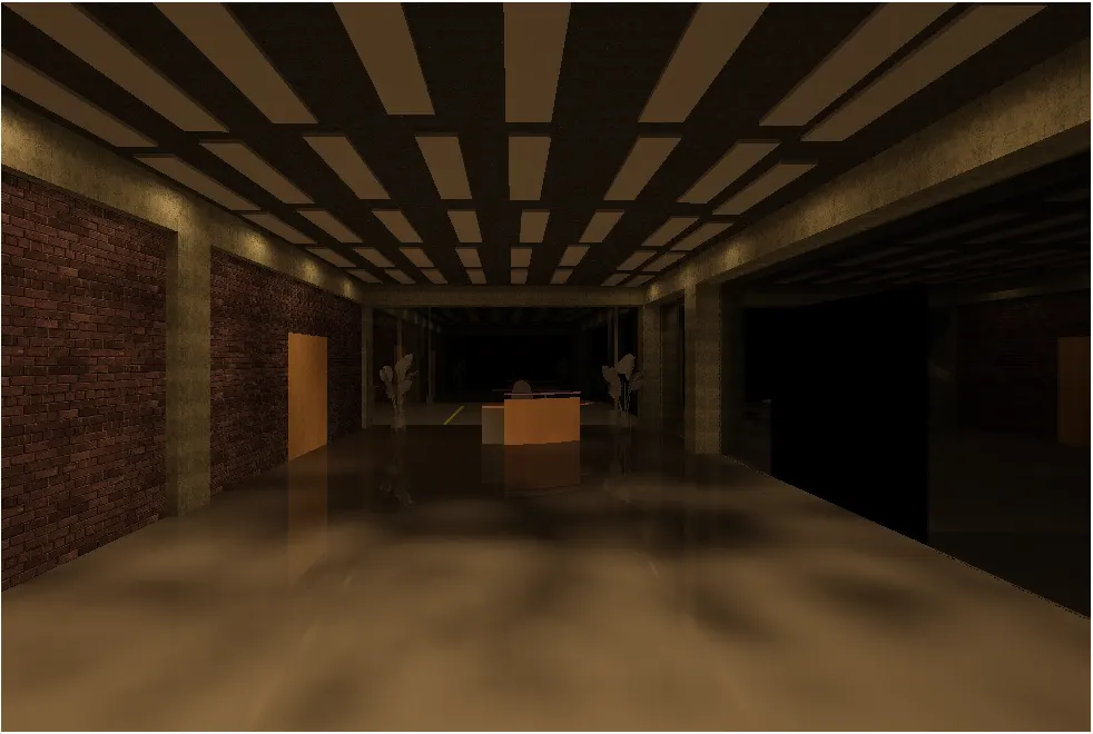
- Repeat the above process for creating camera view and rendering views.
Step III(Including the rendering image to the drawing sheets):-
- Go to View -> Sheet Composition -> Sheet.
- From the "New Sheet" tab click on the "Load" button and select "D 22 X 34 Horizontal".
- Specify new parameters to the sheet such as owner name, issue date, sheet number etc.
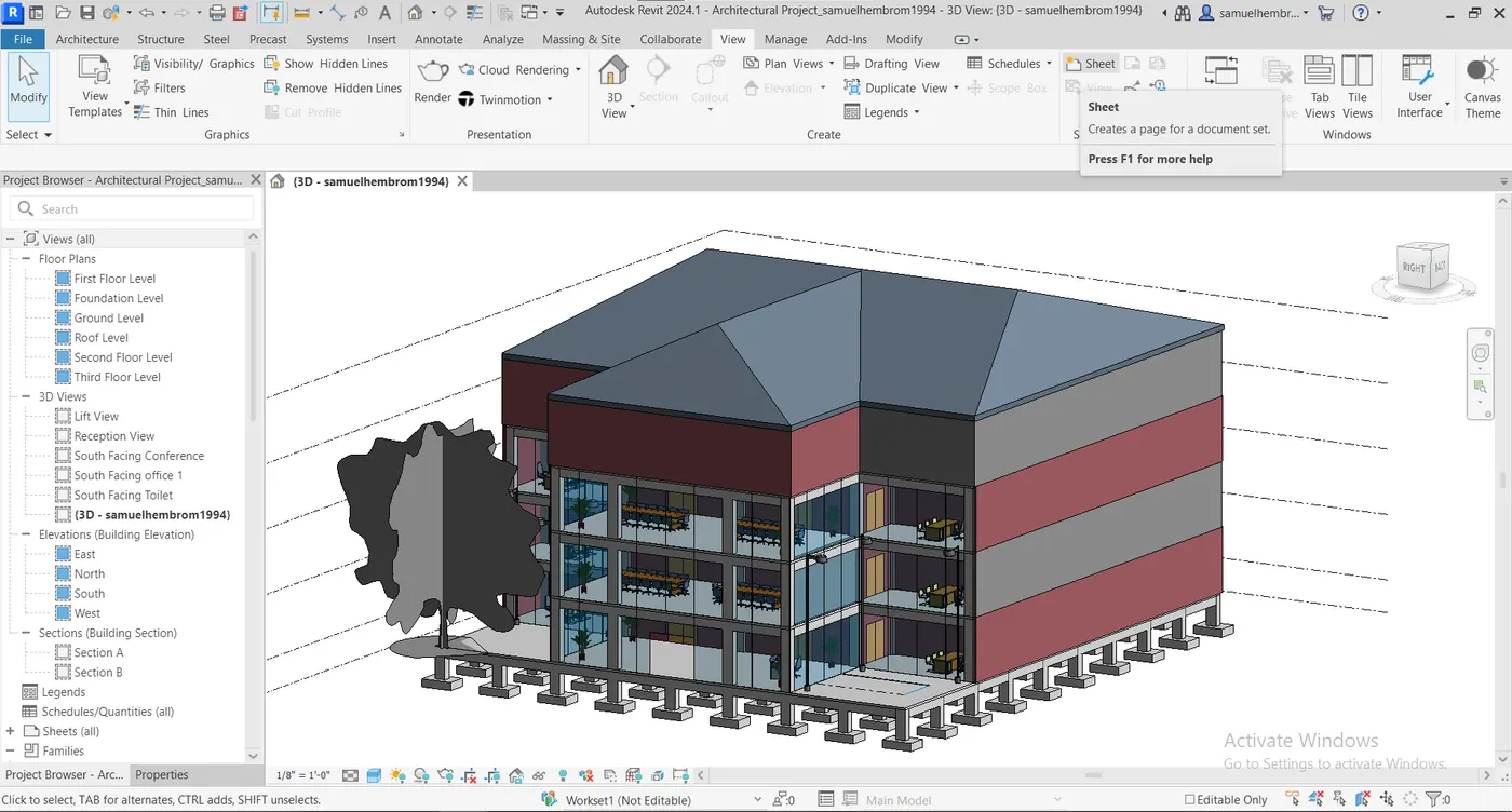
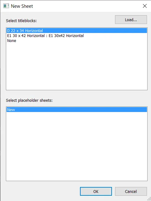
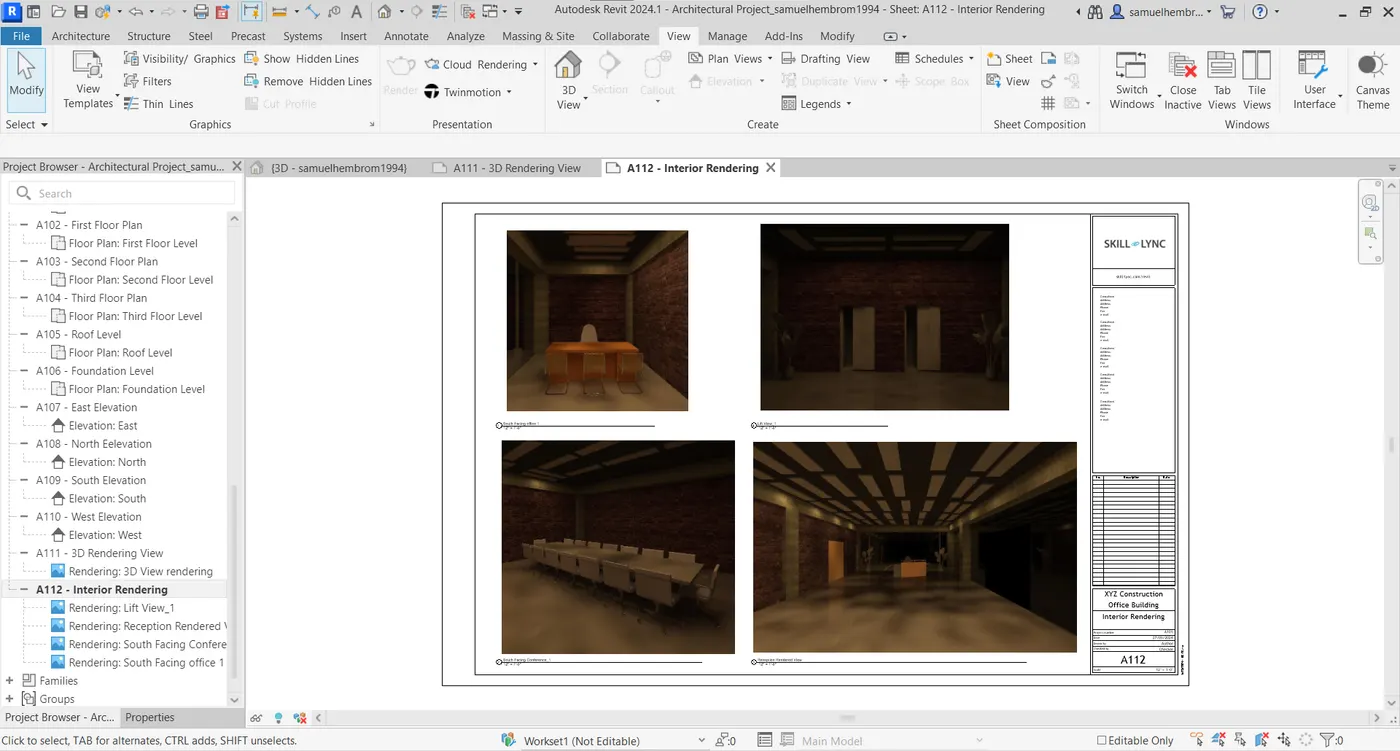
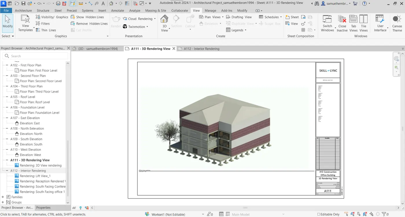
- From the project browser under the Rendering section select the rendered views and drag them to their respective sheets.
- I have selected two sheets separately for Interior rendering and exterior rendering, which are as follows:-
Q No 7:-
Ans:-
Aim:- To print the set of drawing sheet created and submit the drawings from the architecture and structure model.
Procedure:-
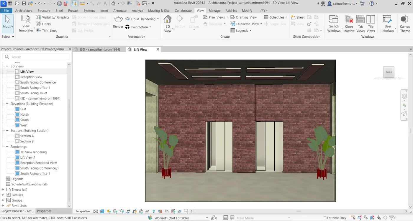
- Open the view required for printing.
- Type CTRL + P on the keyboard.
- "Print" dialogue box will appear.
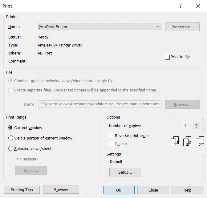
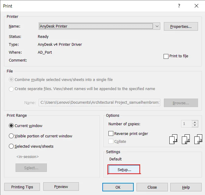
- We can use the setup button for setting up the printing preferences as well.
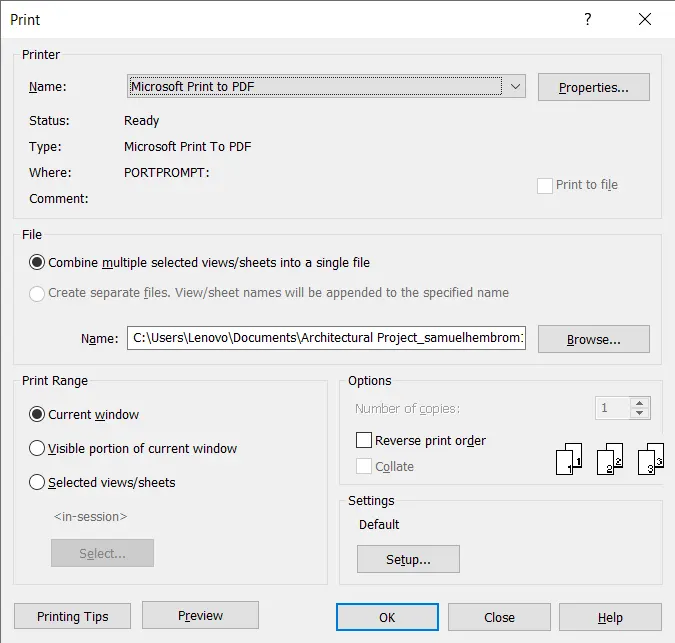
- Press "OK" for printing the views or we can change the printing format to pdf from the "Name" drop down menu, as shown in image below.
- Repeat the process for all the other rendered views.