Creating Conceptual mass in REVIT and Creation of Sinusoidal curve and a Parametric stadium using Dynamo
Introduction:-
Dynamo is an open source visual programming language for Revit, written by designers and construction professionals. It is a programming language that allows you to type lines of code; while also creating an algorithm that consist of nodes.
Using dynamo work can be carried out with enhanced BIM capabilities in Revit. Dynamo and Revit can together be utilized to model and analyze complex geometries, automate repetitive processes, minimize human error and export data to excel and other file types. Dynamo can make the design process more efficient with an intuitive interface and many pre made scripting libraries available as well.
The user interface for dynamo is organized into five main areas, largest being the workspace where programs are processed and this used interface sections include
- Main Menu
- Toolbar
- Library
- Work Space
- Execution Bar
The workspace is the place where designers develop visual programs but it is also the place where any elaborate geometry is previewed.
Conceptual mass of a building contains different types of parameters like level, floor area, floor perimeter and architect can generate early quantities takeoff from the mass. In BIM modelling services the conceptual mass of a building can be exported to any other format for performing early energy analysis.
Q No.1
Ans:-
Aim:- To create a set of sinusoidal points, a curve and a surface out of the curve using dynamo.
Procedure:-
Step -I(Opening Dynamo):-
- Open the Revit software.
- Open a New "Architectural" template.
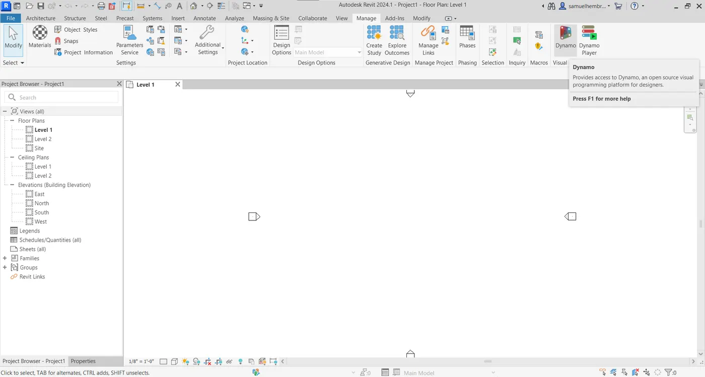
- Go to Manage -> Visual Programming -> Dynamo.
Step - II(Opening a New file in Dynamo):-
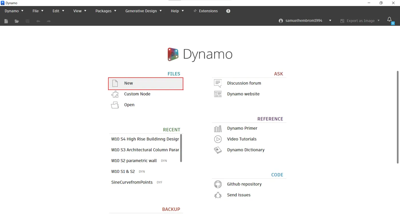
- In the Files section click on "New".
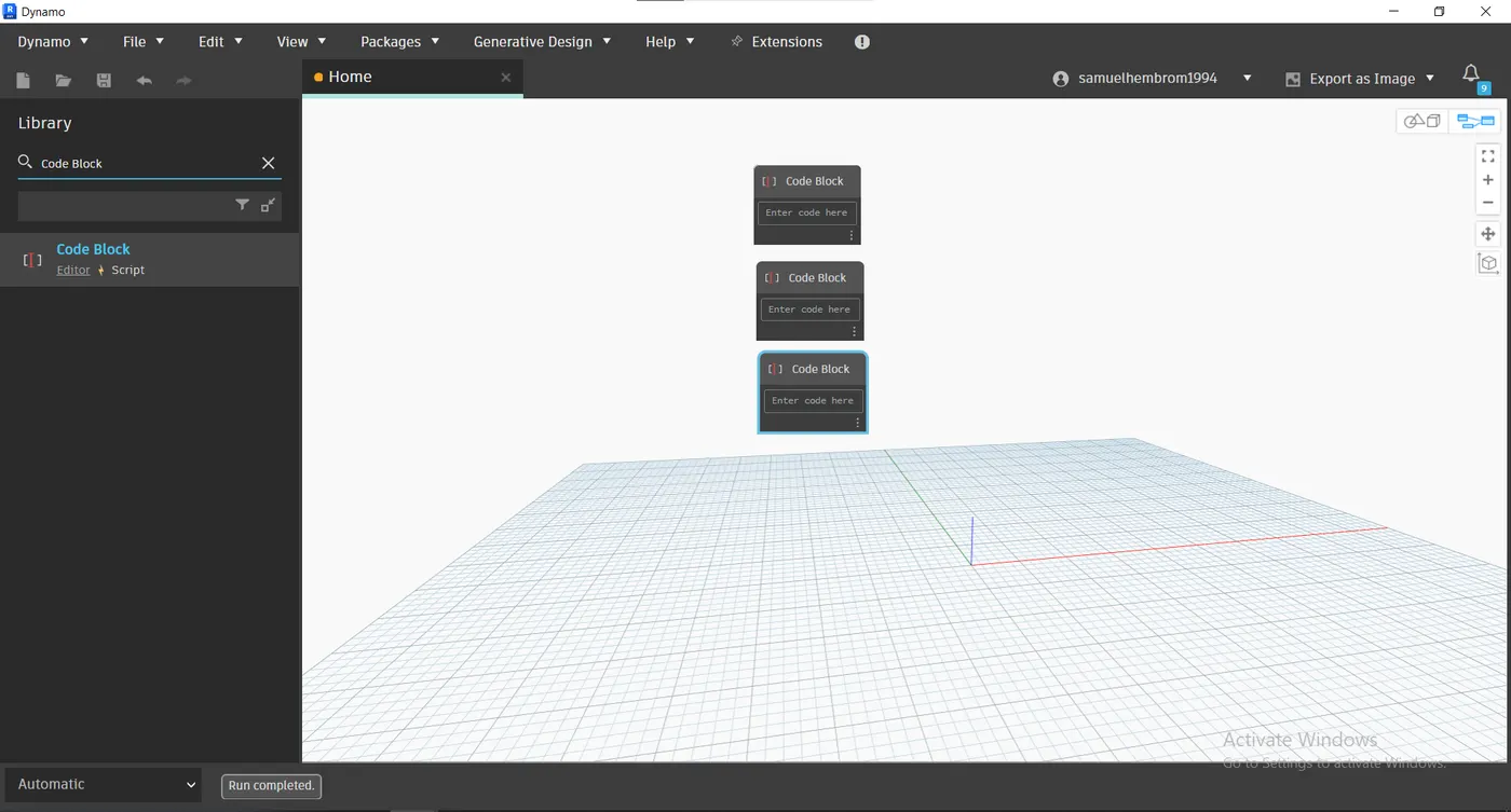
- In the search bar from the library search for "Code Block" and add three of them.
- Rename them as "start", "end" and "step" & assign the values as 10, 200 & 1 respectively.
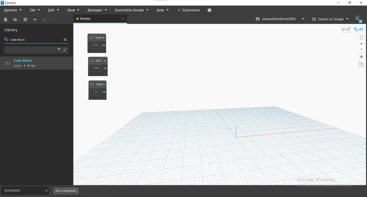
- Search for "Range" & "Point By Coordinate" in the search bar in Library and add them.
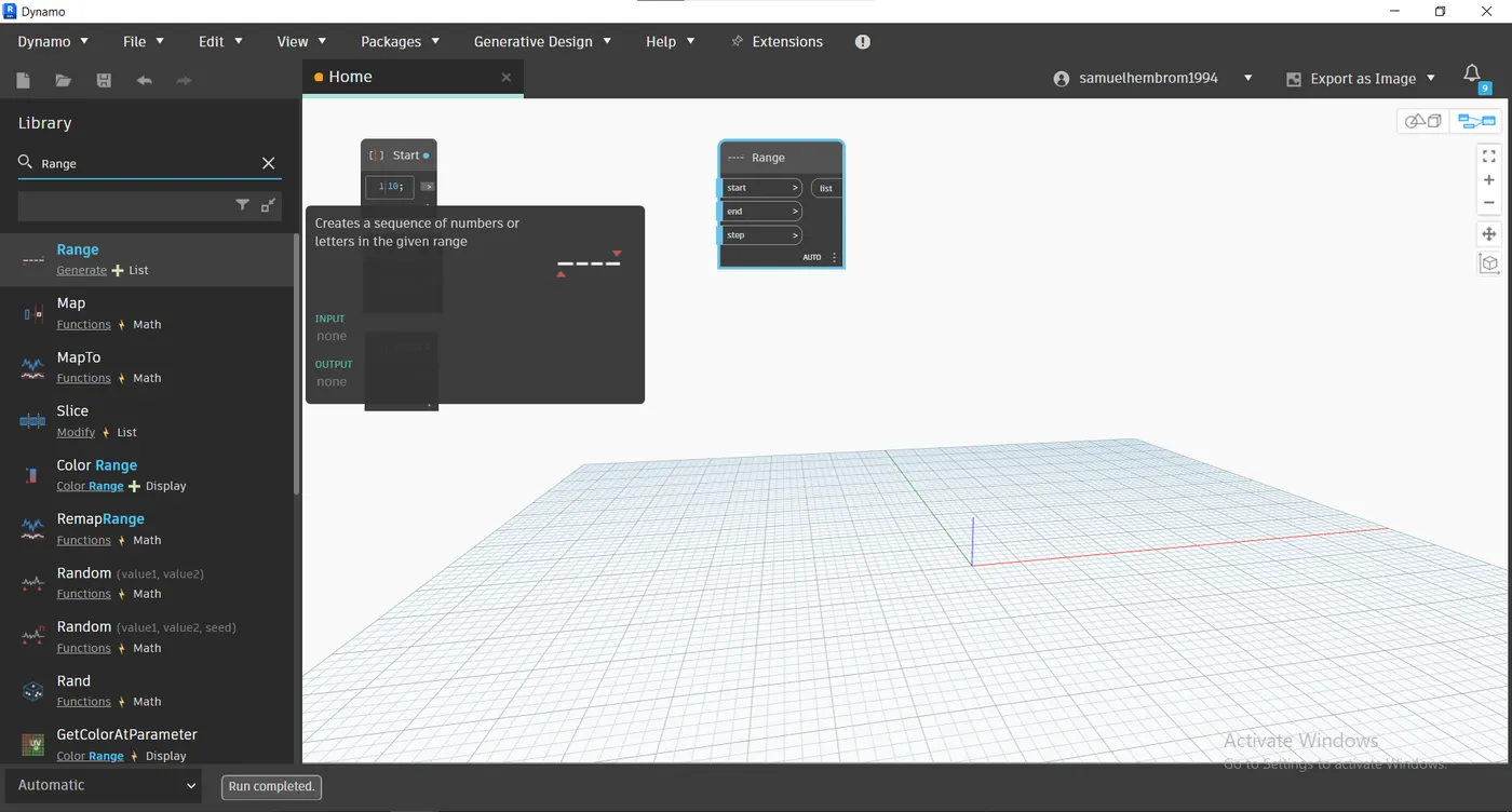
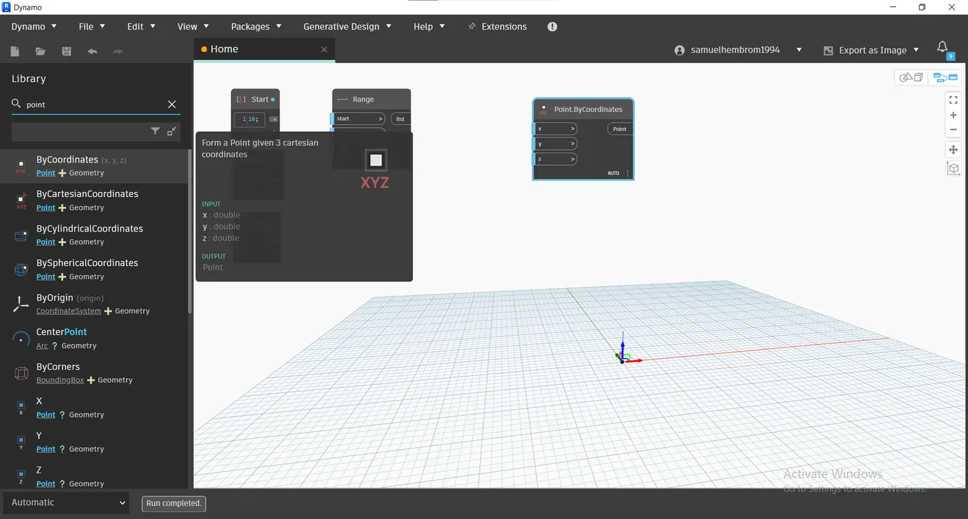
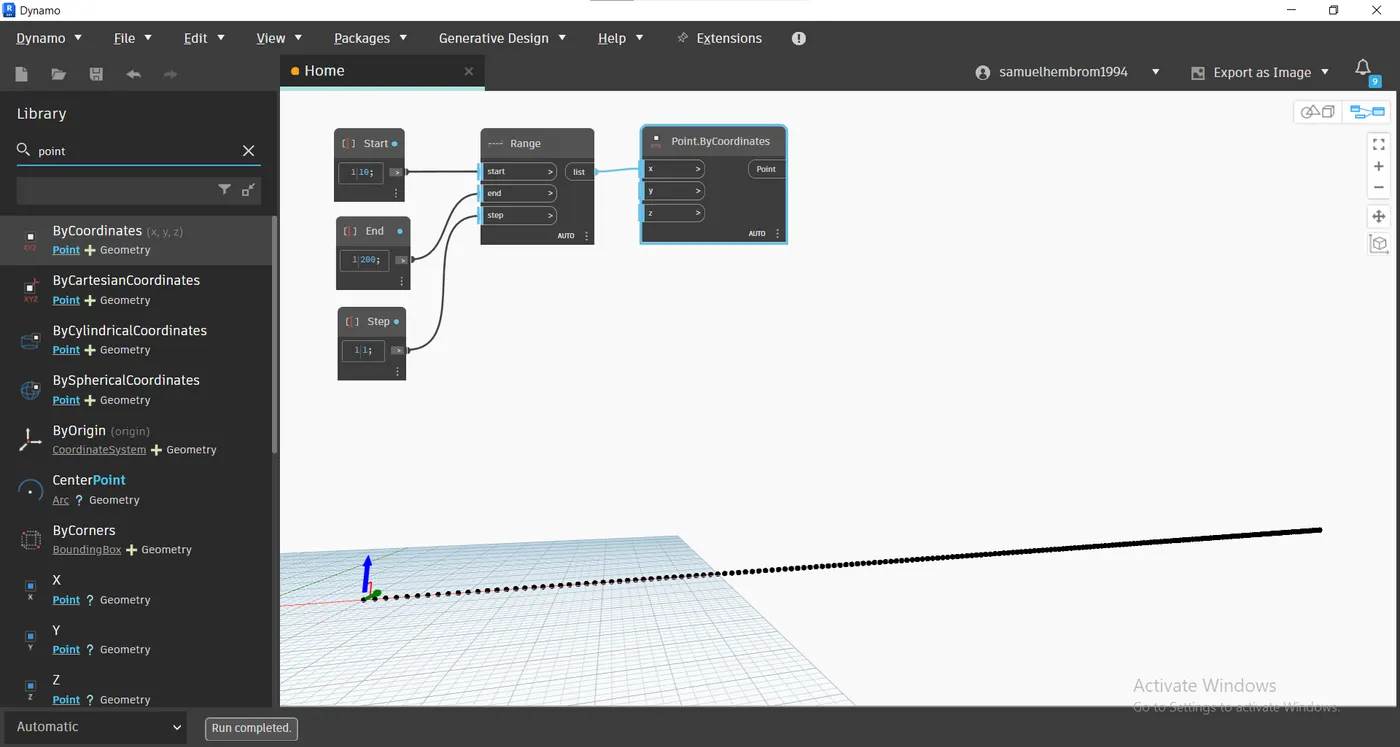
- Connect all the elements as shown in image below to form a line of points in X-axis.
- For Y values based on the X values we will add "Math.Sin" from the search bar in the library.
- Also we need to add a "Code Block" for amplifying these sine values.
- So add a "Code Block" from the library and rename it as "Amplifier".
- Assign a number of 20 to the "Amplifier" block.
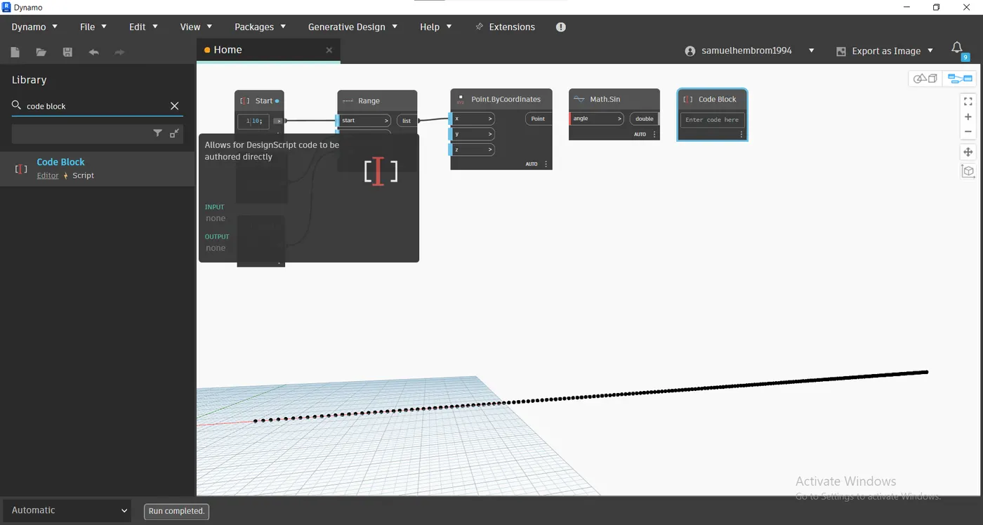
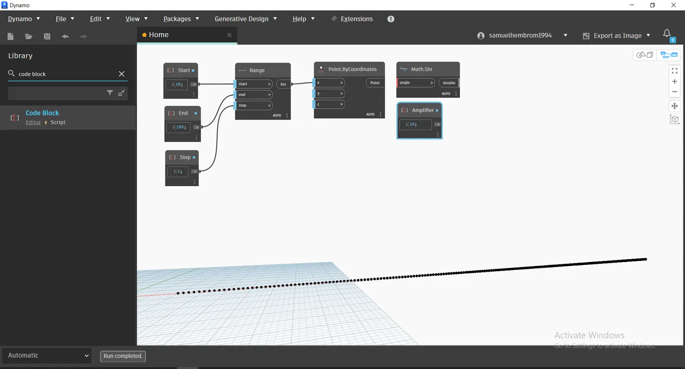
- We have to multiply the sine values to amplifier.
- Search for math operator "product" in the search bar in the library and add it.
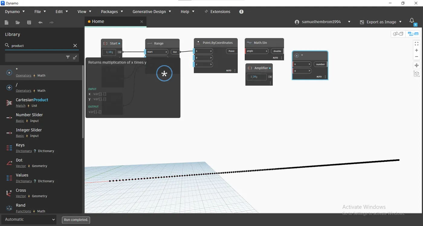
- Connect the "Range" to the "Math.Sin" & Connect "Math.sin" and "Amplifier" to the "Product block" as shown in image below.
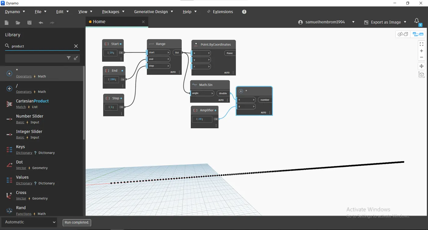
- Every Sine values has a phase so from the "Library" we will add a "Integer Slider" for providing values to the phase.
- Set the maximum and minimum values of "Integer Slider" as 20 & 50 respectively.
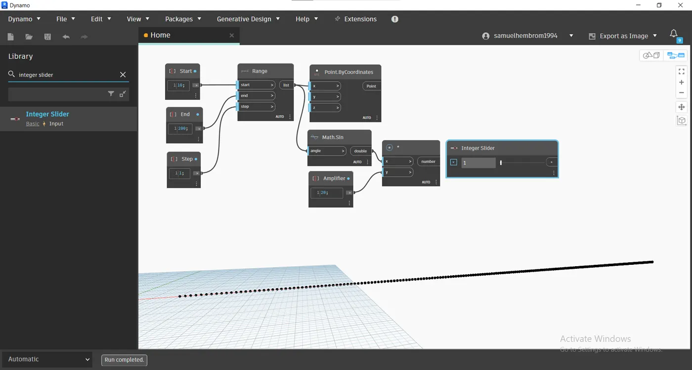
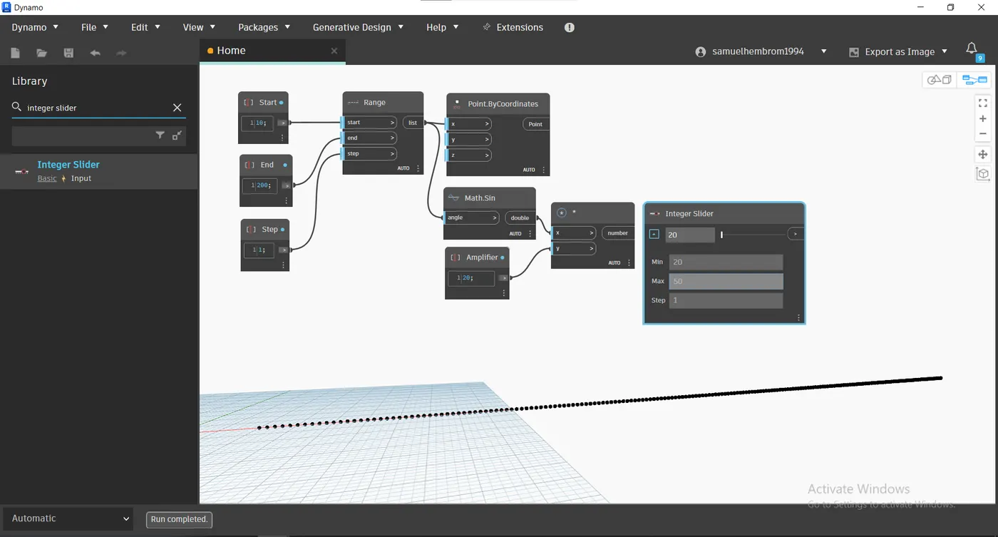
- In order to add my amplified value to the phase we need to add an "Add" math operator from the library to have the final Sinusoidal Value.
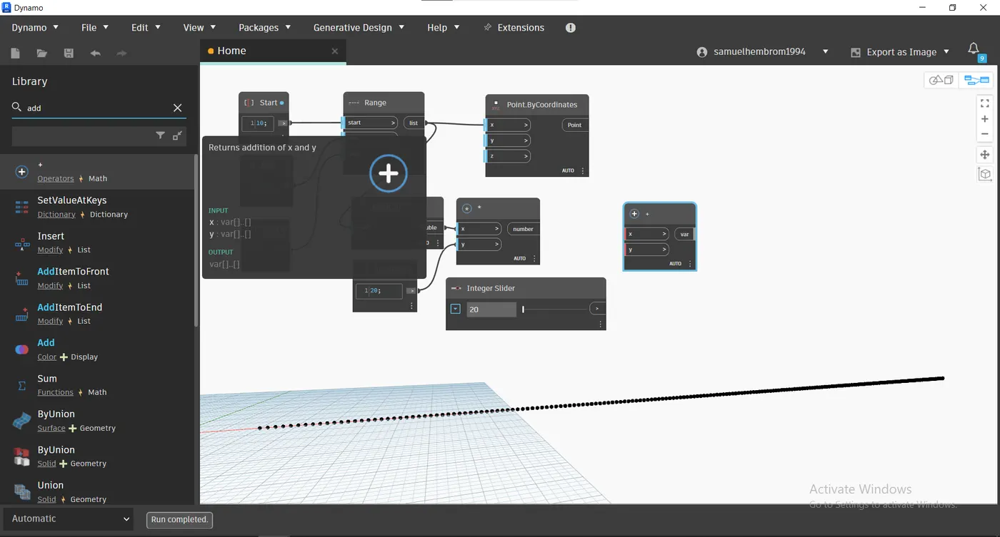
- Join the product value and integer slider to the "Addition" operator block as shown in image below.
- Also join the "Add" block to the y value of the "Point. By Coordinate" block.
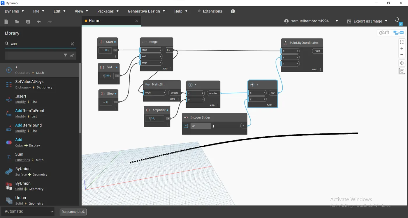
- Change the value of "End" block from 200 to 500 to get a more appalling curve.
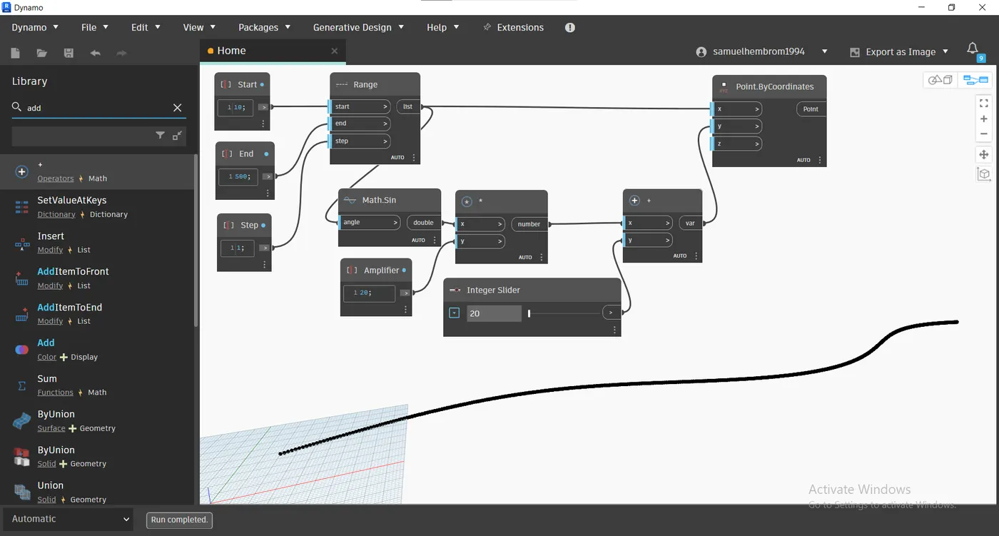
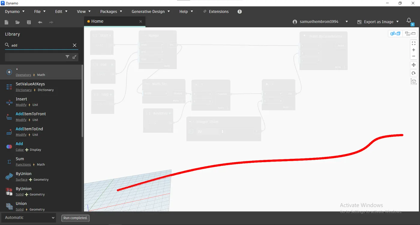
- For joining the control points we need to add a "Line" block.
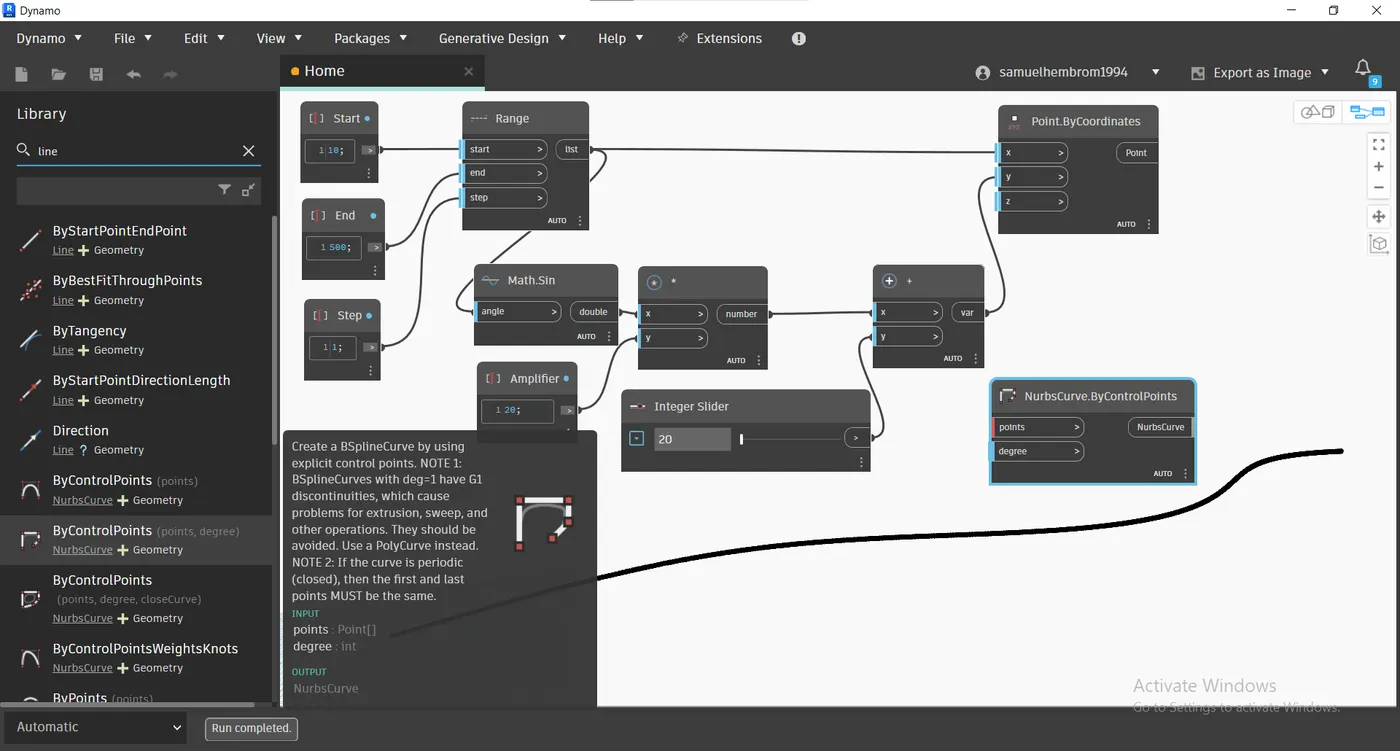
- Join the "Points. By Coordinate" and "Line" block as shown in image below.
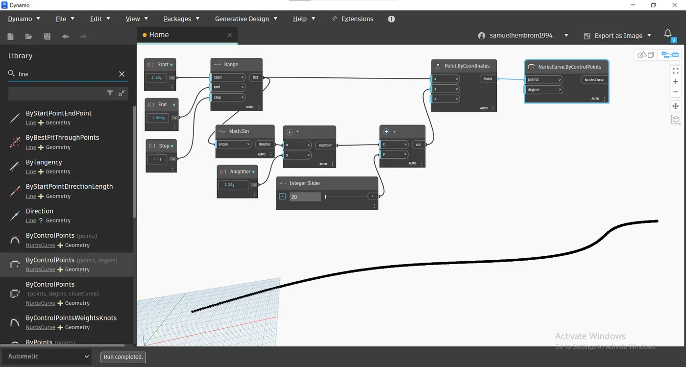
- For adding degrees we add an "Integer Slider" from the library and set the maximum and minimum values as 2 and 5 respectively.
- Join the "Integer Slider" to the degree of the "NurbsCure.ByControlPoints".
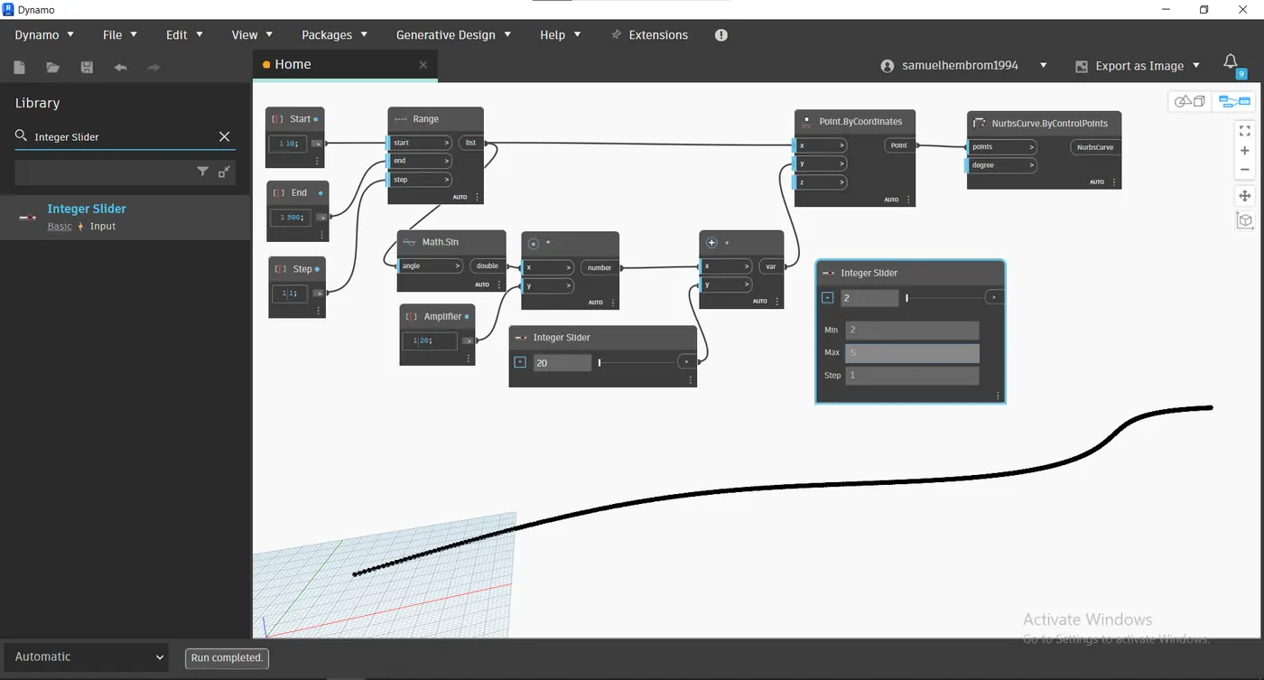
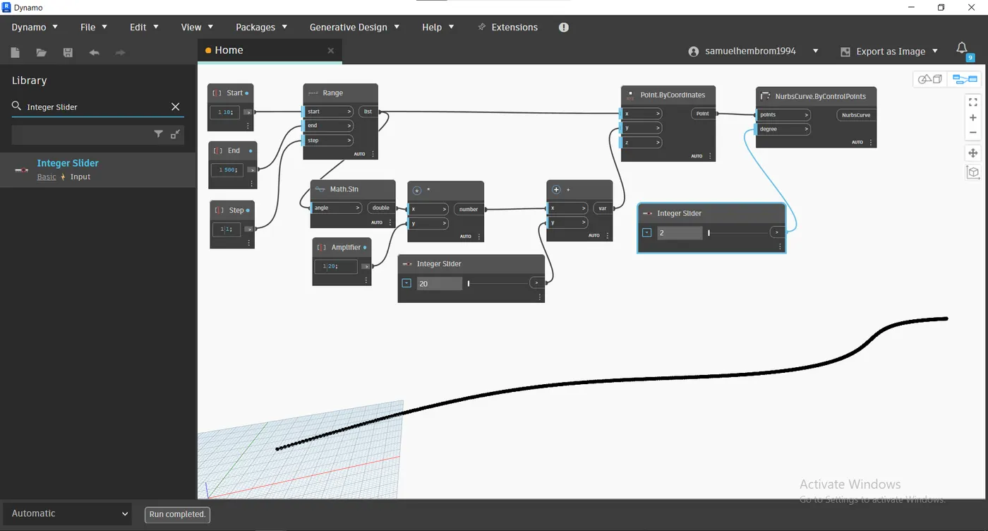
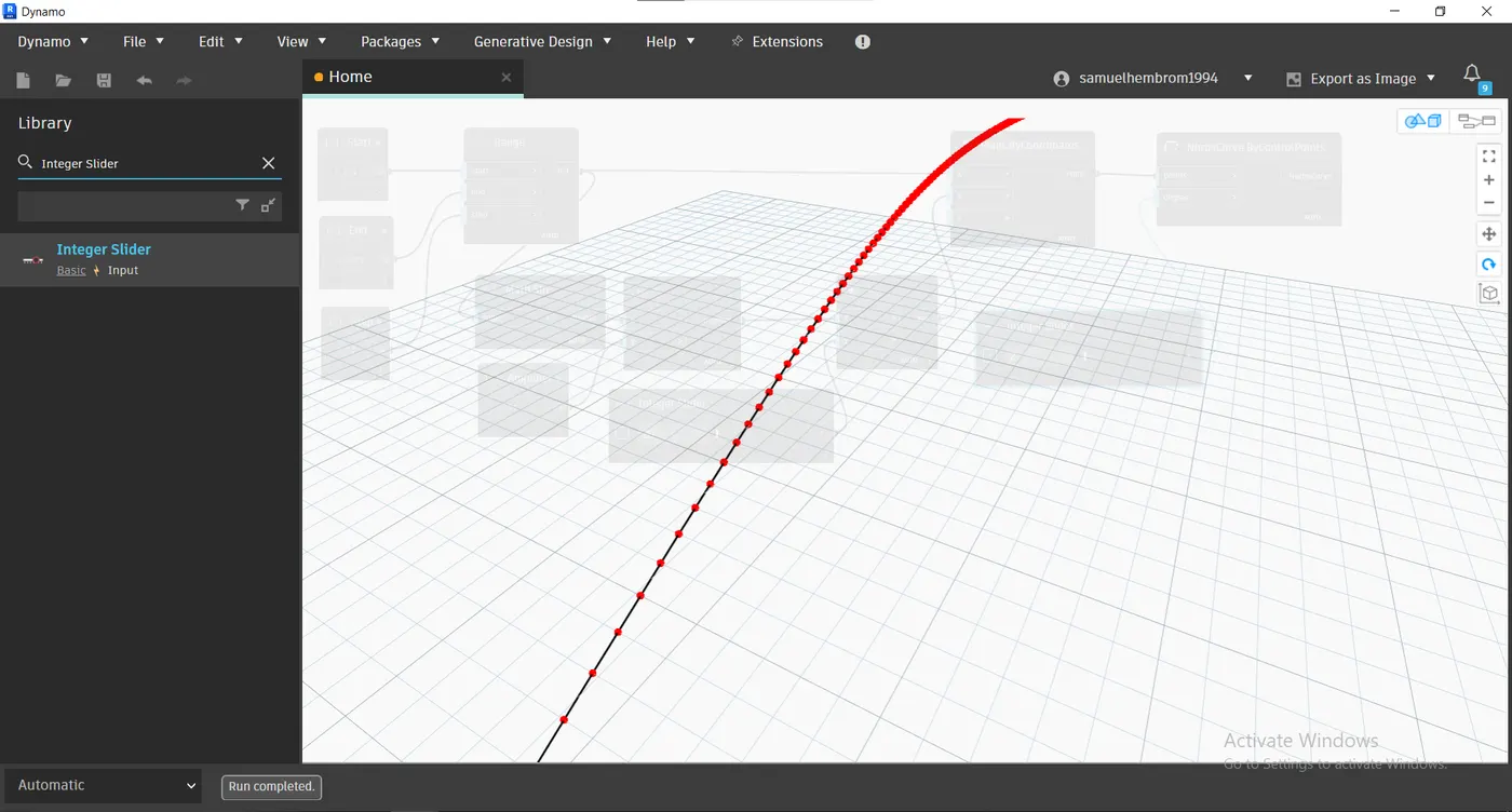
- Select all the "Output" and "Processing" blocks and go for "Edit" in Menu bar.
- Select "Create Custom Node" from the "Edit" menu.
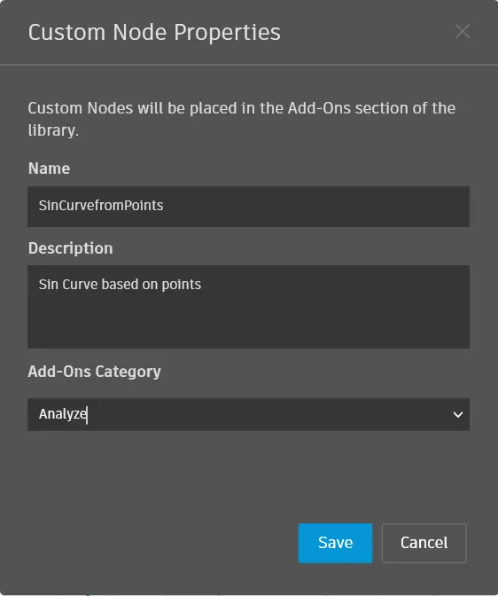
- Provide Name as "SinCurvefromPoints" , Description as "Sin Curve from Points" & Add-Ons Category as "Analyze" in "Custom Node Properties" tab.
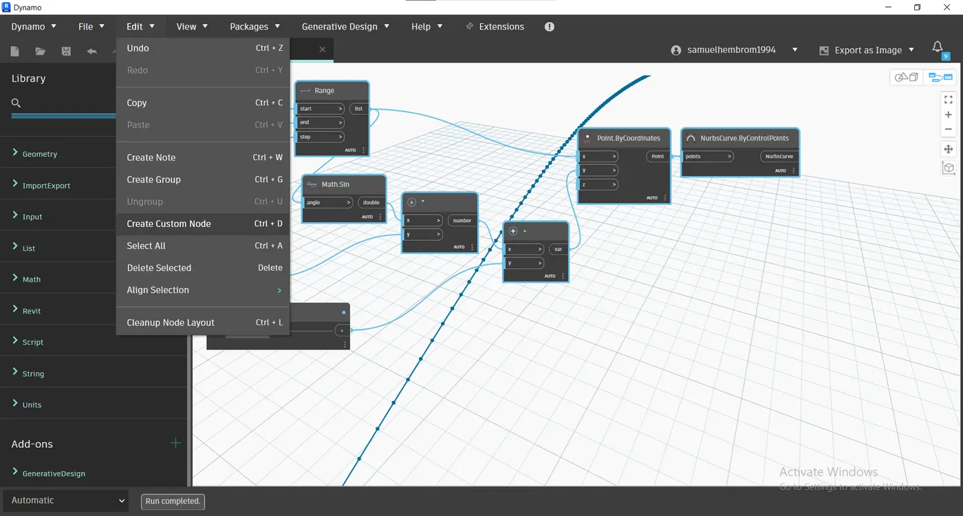
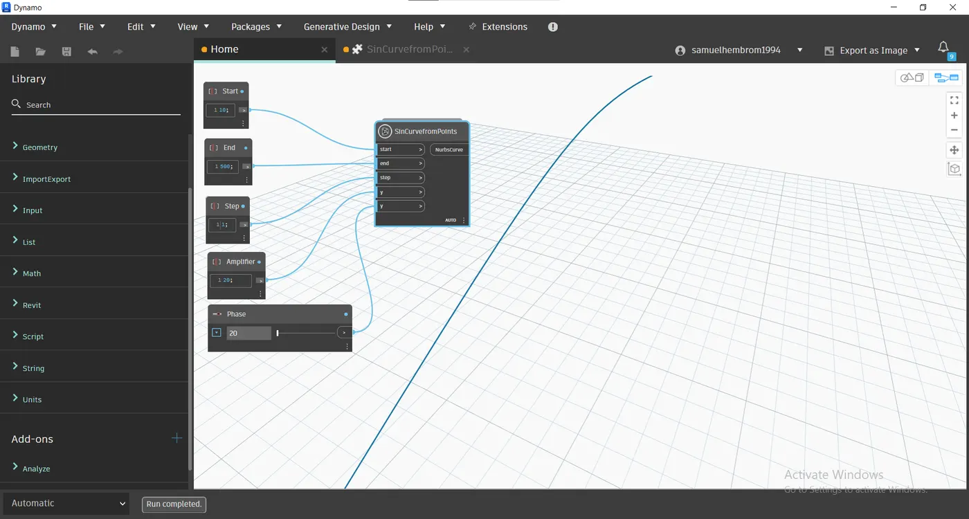
- In the above image we can see that we have to y values in "SinCurvefromPoints" block.
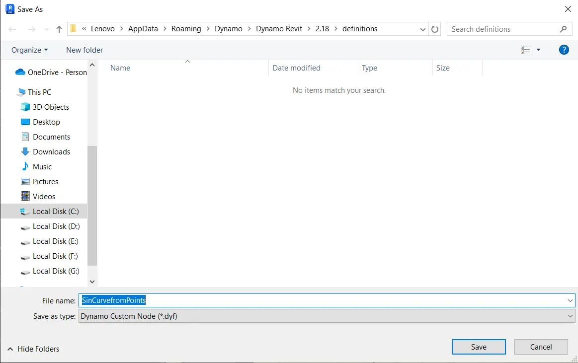
- So we Rename bottom two inputs as "Amplifier" and "Phase" and save it as shown in image below.
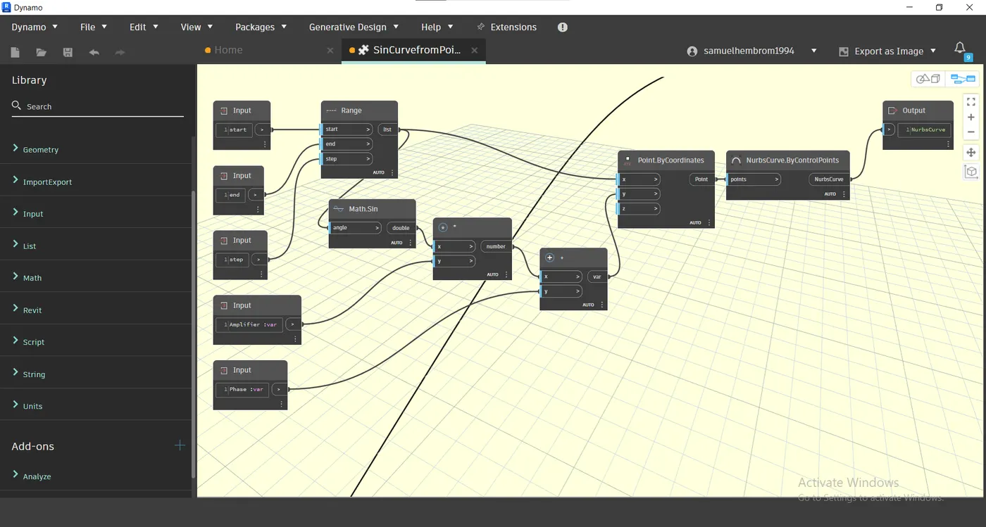
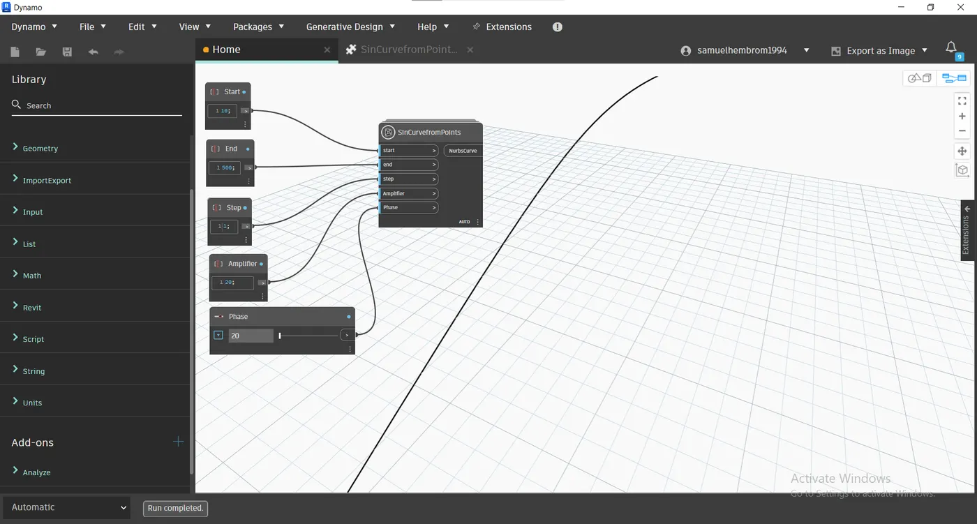
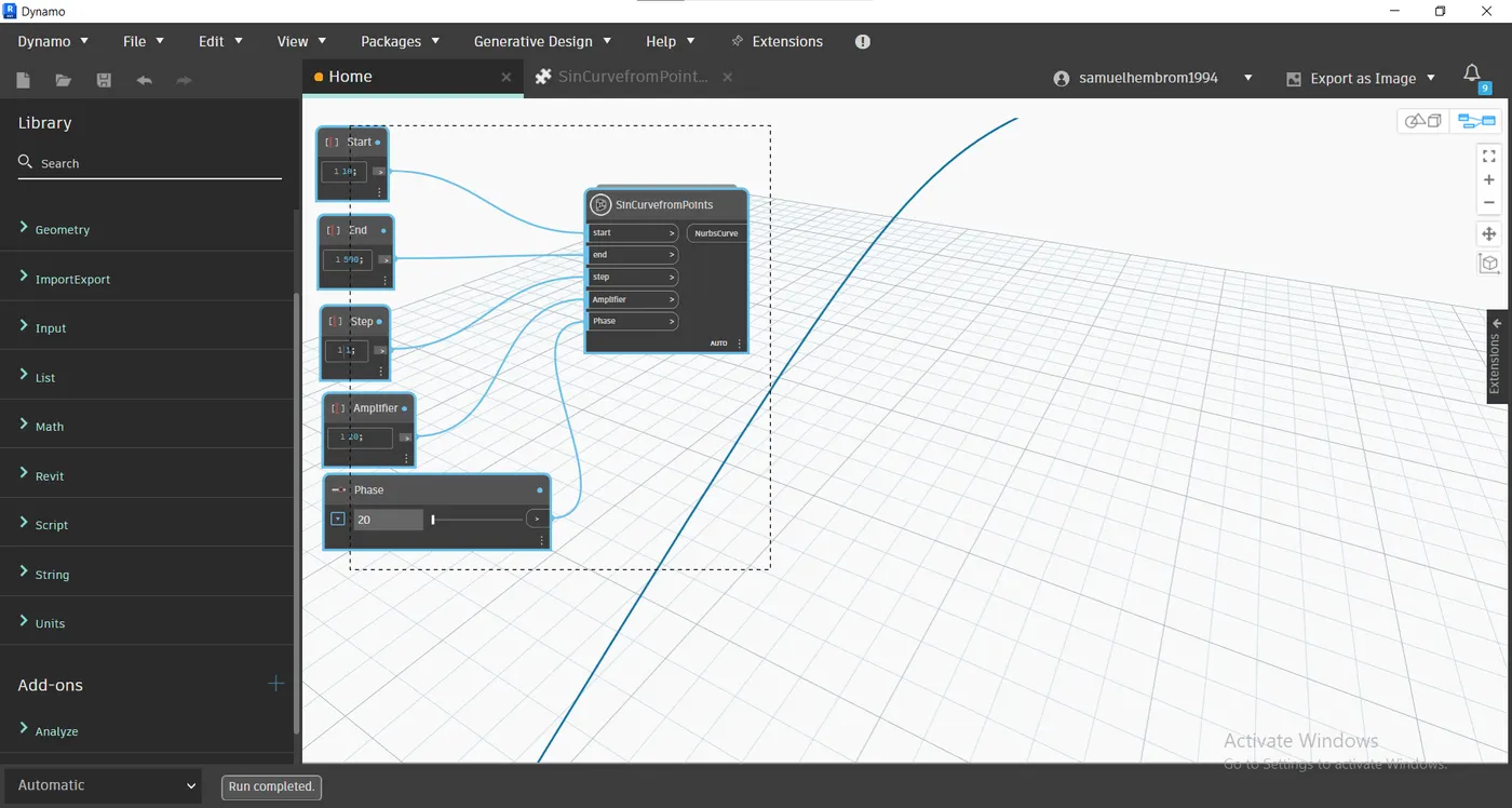
- Select the above blocks and copy them and paste them so that we can create two more curves by changing phase values.
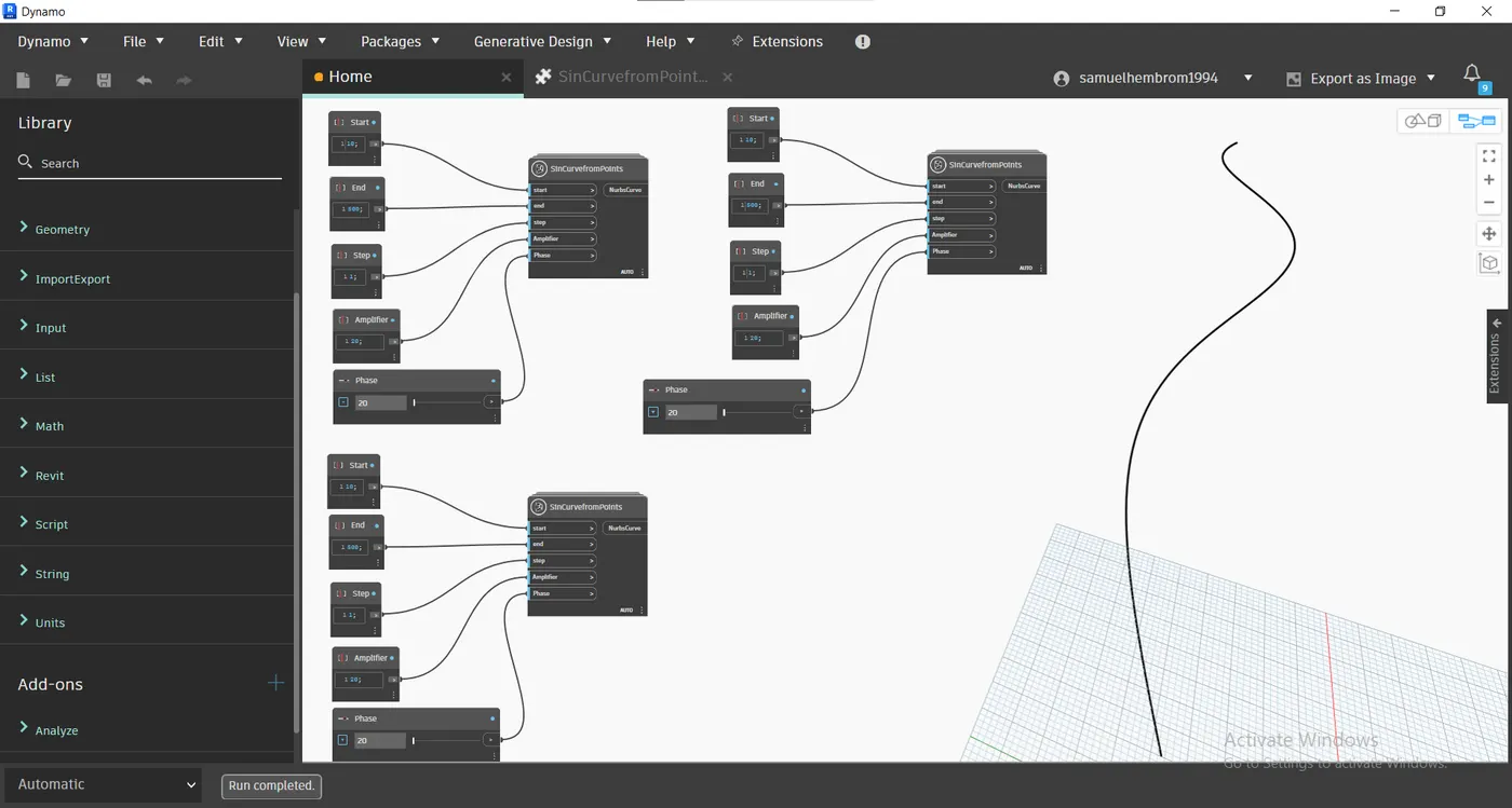
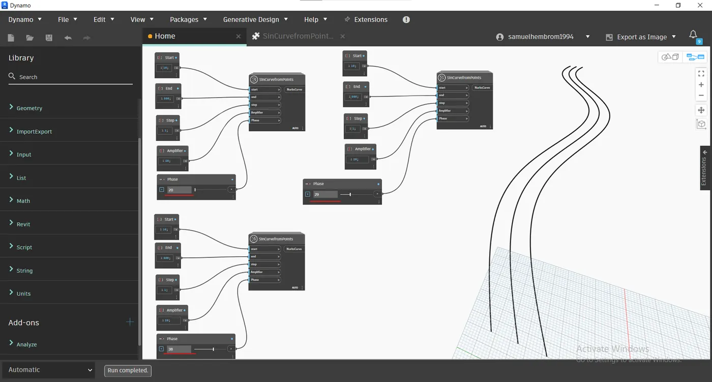
- In order to create a surface out of the curve we have to add a "List" because the "Loft" command only takes list values.
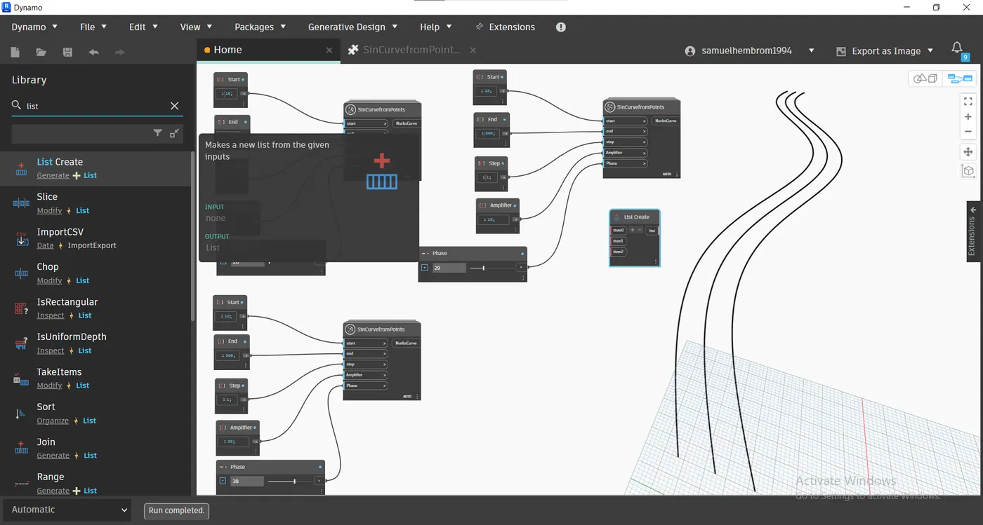
- Join all the "SinCurvefromPoints" values to the "List Create" block as shown in image below.
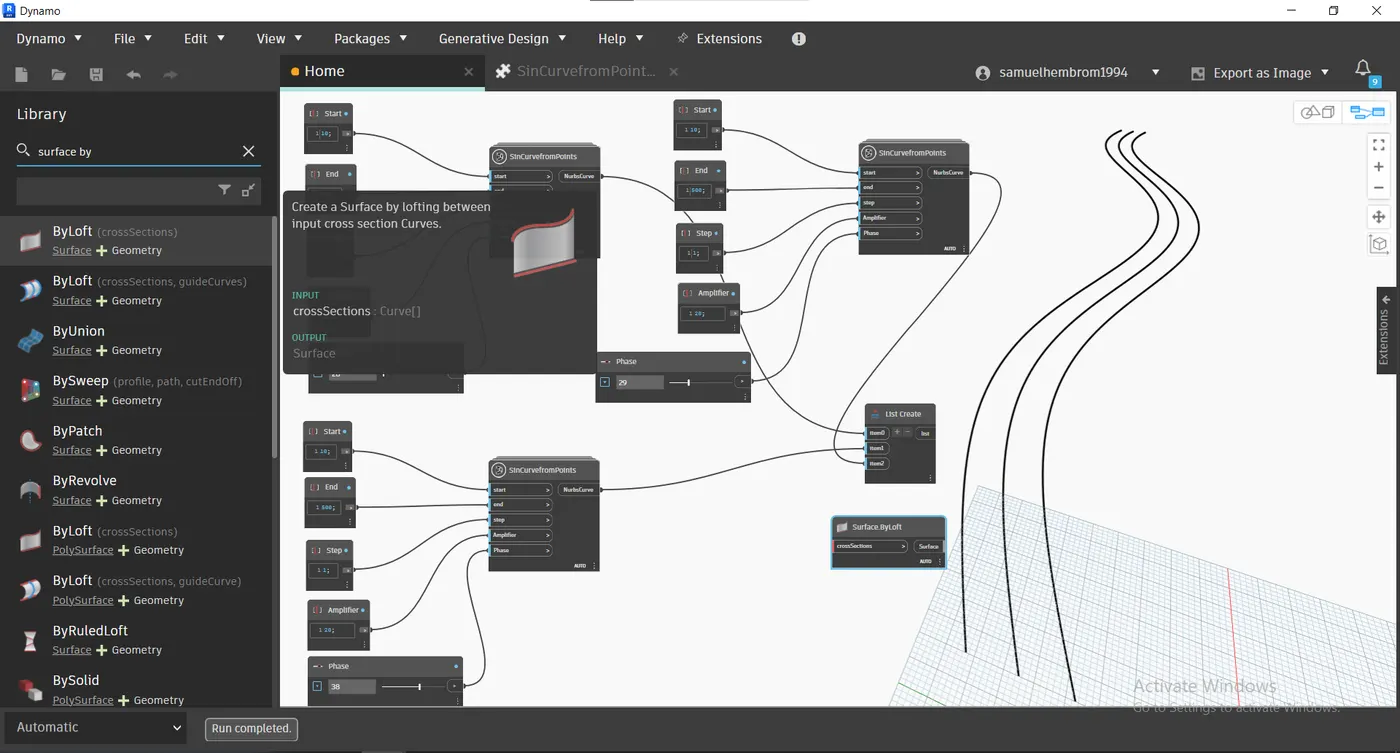
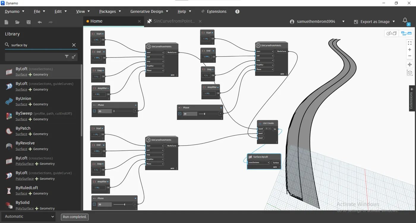
- Join the "List Create" block to "Surface.ByLoft" block and we will be able to see that a surface have been generated out of the curve.
Result:-
A sinusoidal curve is drawn and a surface is made out of it.
Q No.2
Ans:-
Aim:-
To create a conceptual layout of a floor plan in dynamo.
Procedure:-
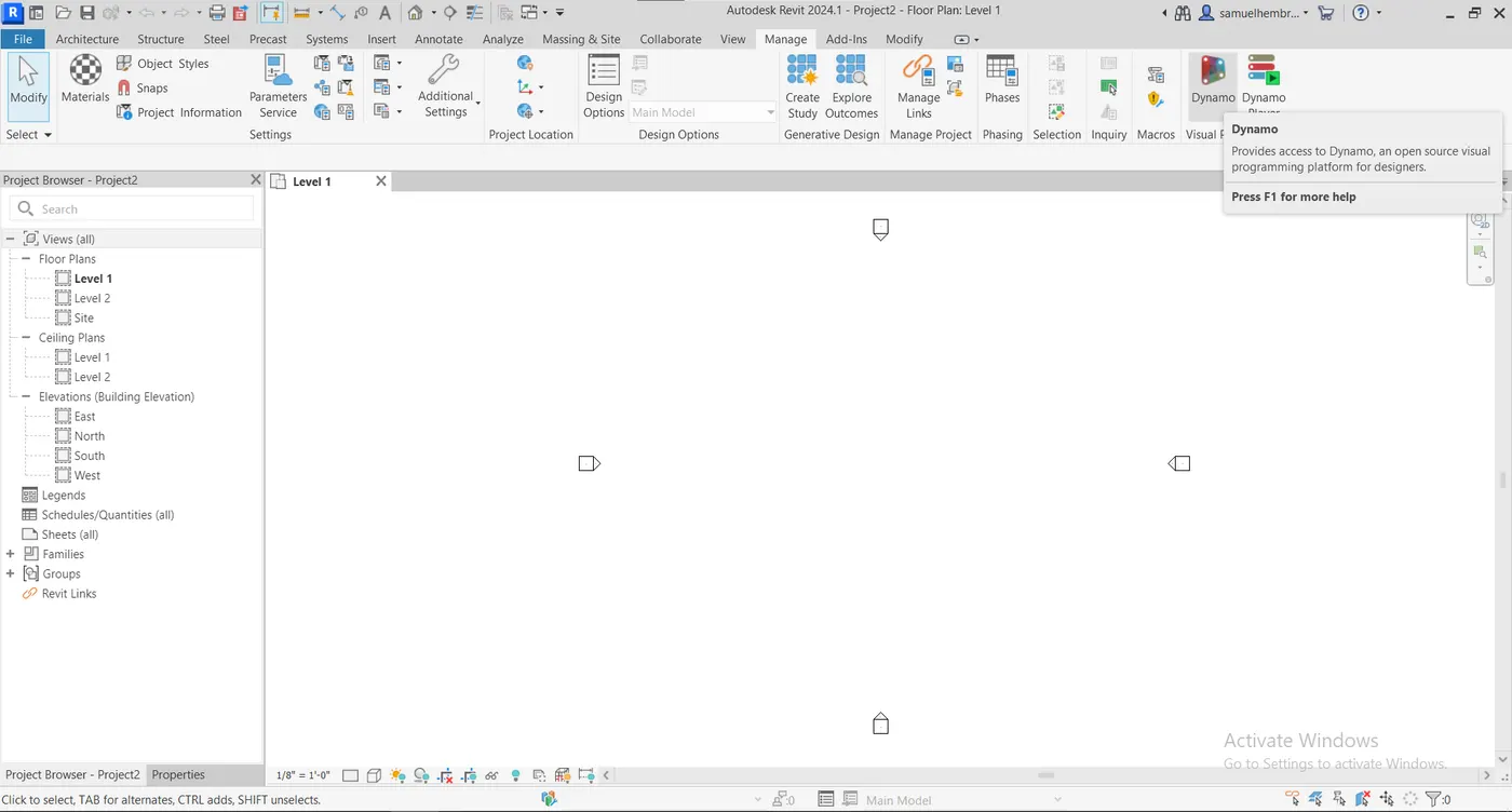
- Open the "Revit" software and open a new architectural template.
- Go to Manage -> Visual Programming -> Dynamo.
- Open a new Dynamo File.
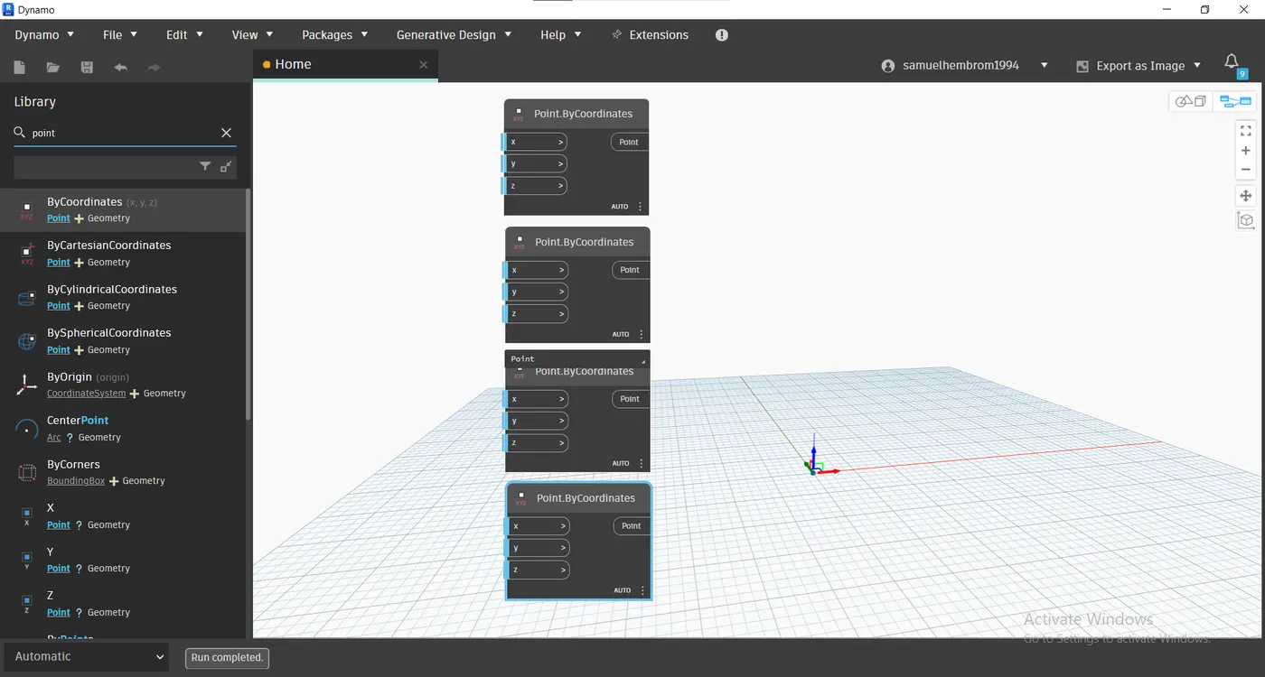
- Type "Point" in search bar of library and add four "Point.ByCoordinate" block.
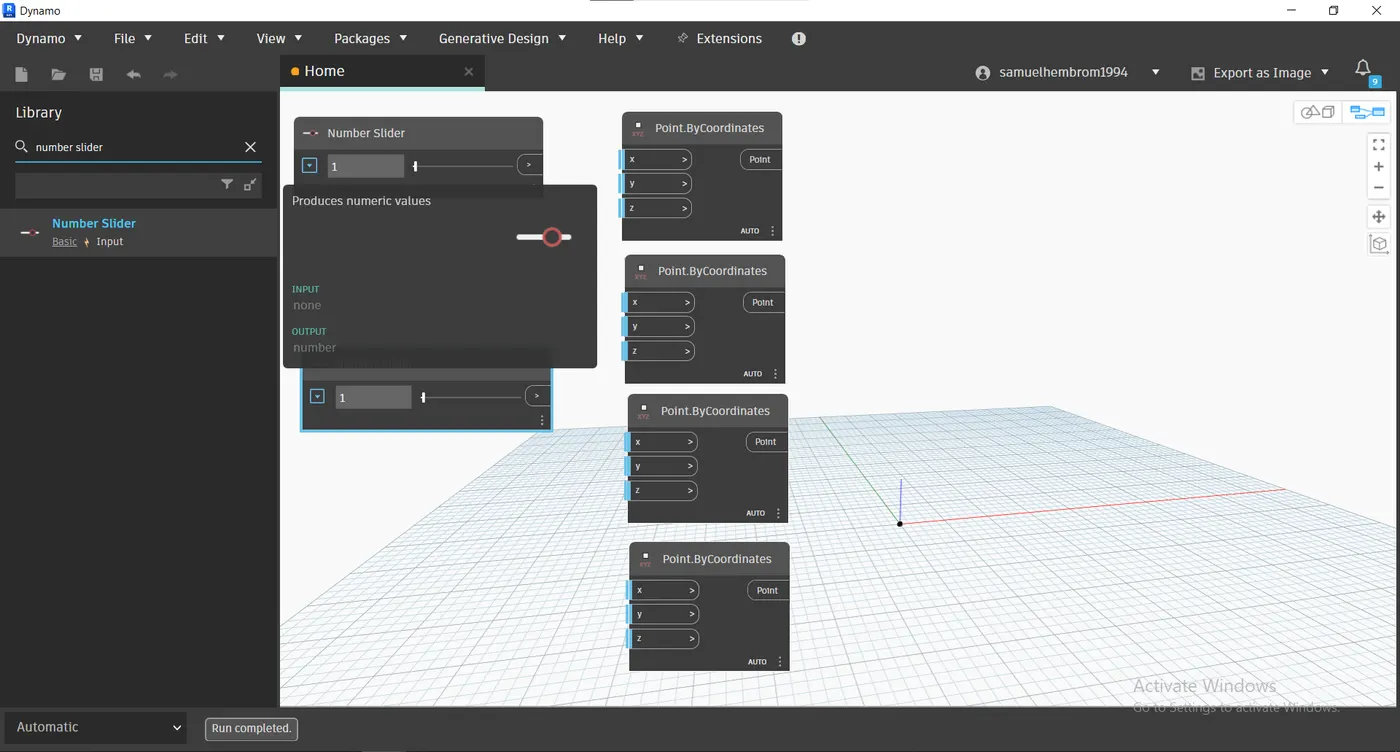
- Again add two number slider from the library.
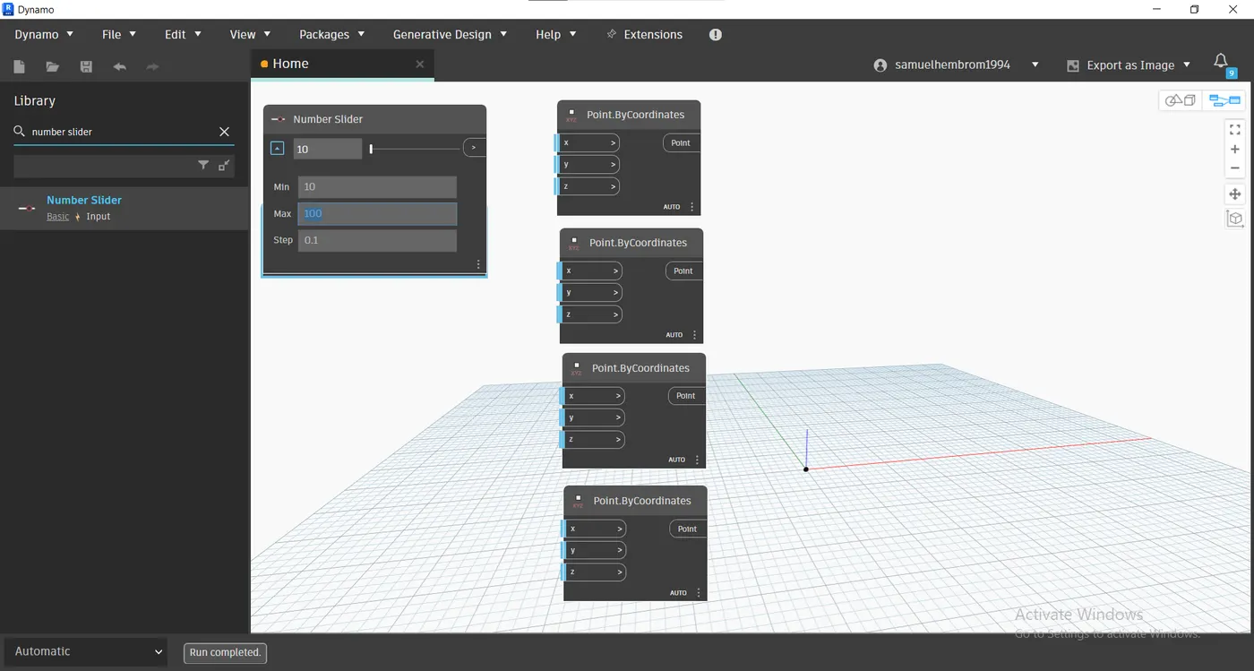
- Set the maximum and minimum values of both the sliders from 10 to 100 respectively.
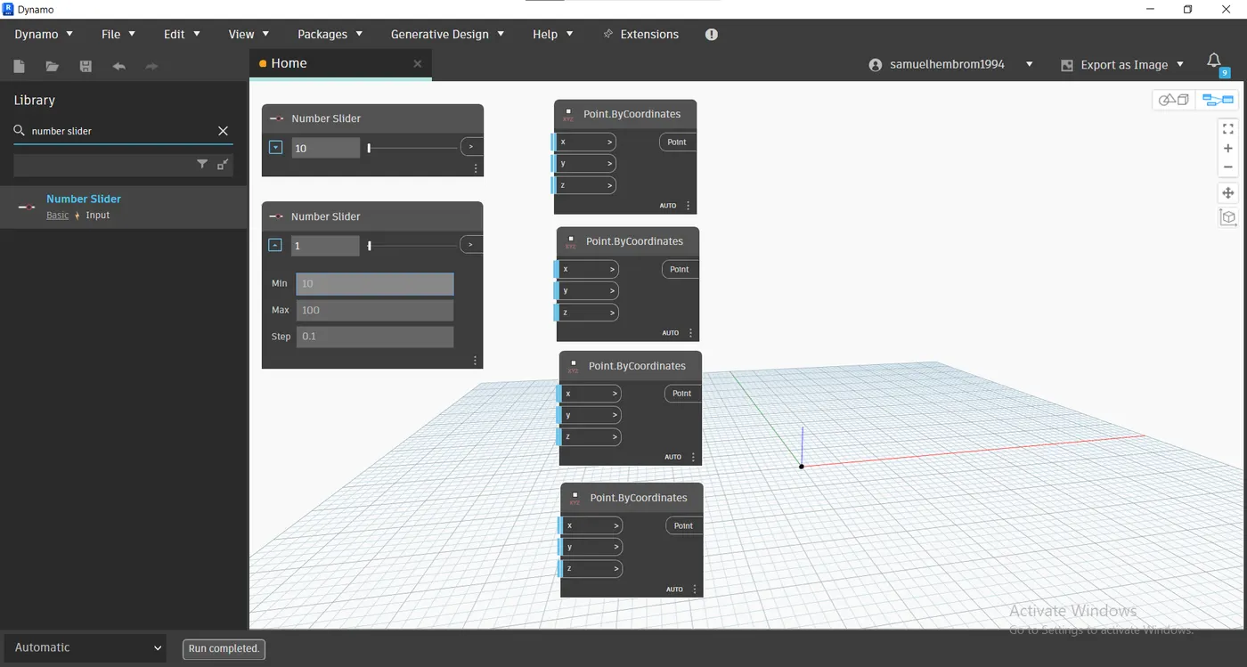
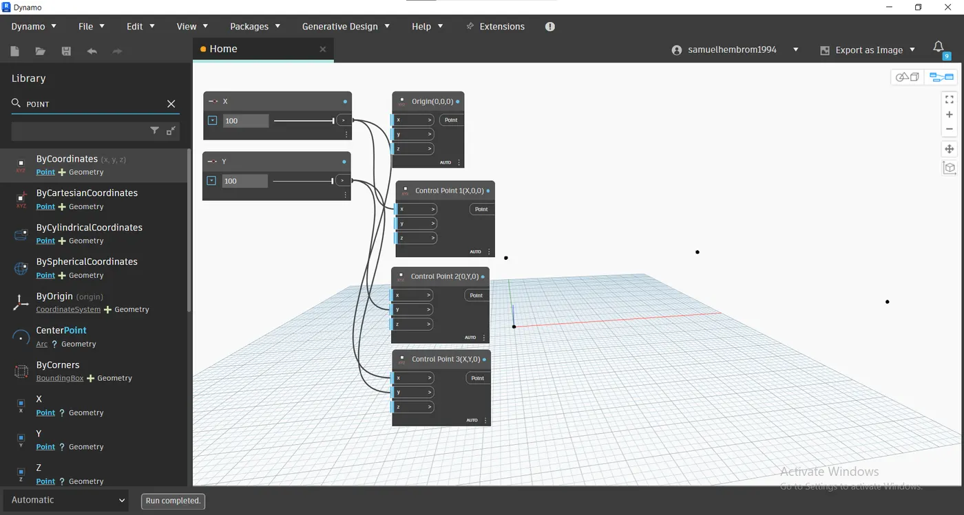
- Rename the "Point.ByCoordinates" to Origin(0,0,0), Control Point 1(X,0,0), Control Point 2(0,Y,0), Control Point 3(X,Y,0).
- Rename the Number slider to "X" and "Y" to respectively.
- Join the "X" number slider to "X" coordinates of the control points and "Y" number slider to "Y" coordinates of the control points block.
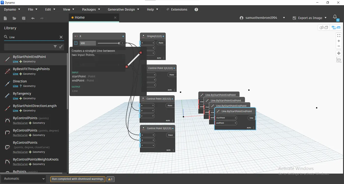
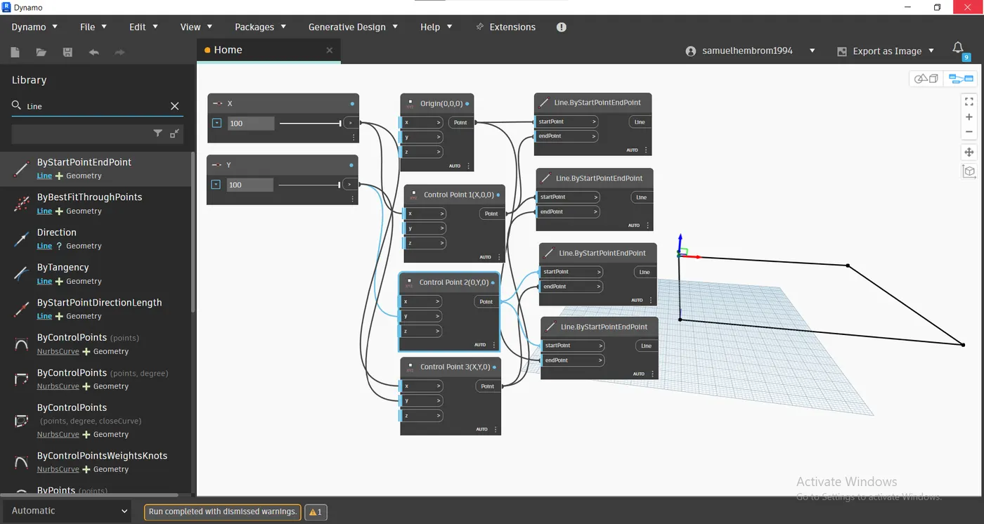
- In the Library's search bar search for line and add four "BystartPointendPoint" block.
- Join the "Origin" and "Control Point" blocks to above added line blocks so that it forms a rectangle in model space.
- Now search for "Wall" and add the "ByCurveAndHeight" option from the list.
- Again add "WallTypes" from the library list & from the drop down menu of "Wall Type" select "Generic-5"" wall.
- Simillarly add "LEVELS" block from the library search bar menu and set it to "Level 1" from the drop down menu of the "Levels" block.
- Add a "Number Slider" and set minimum and maximum values as 10 to 40 respectively.
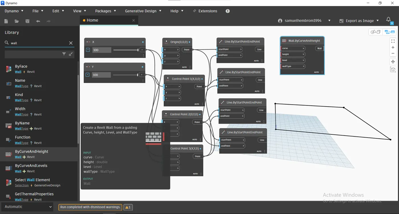
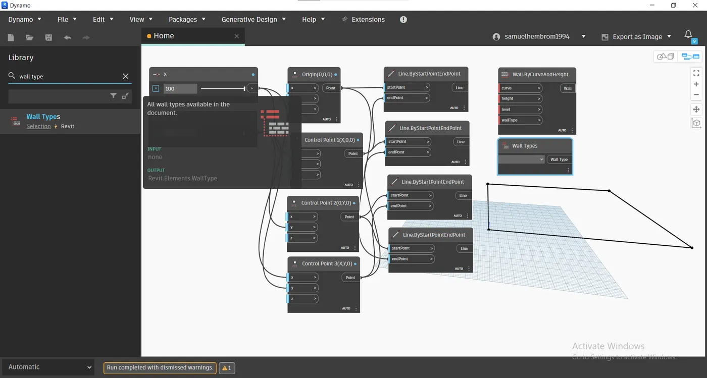
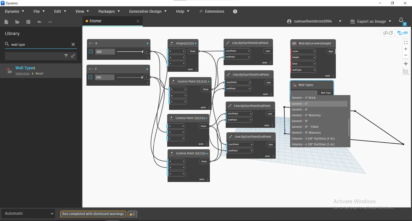
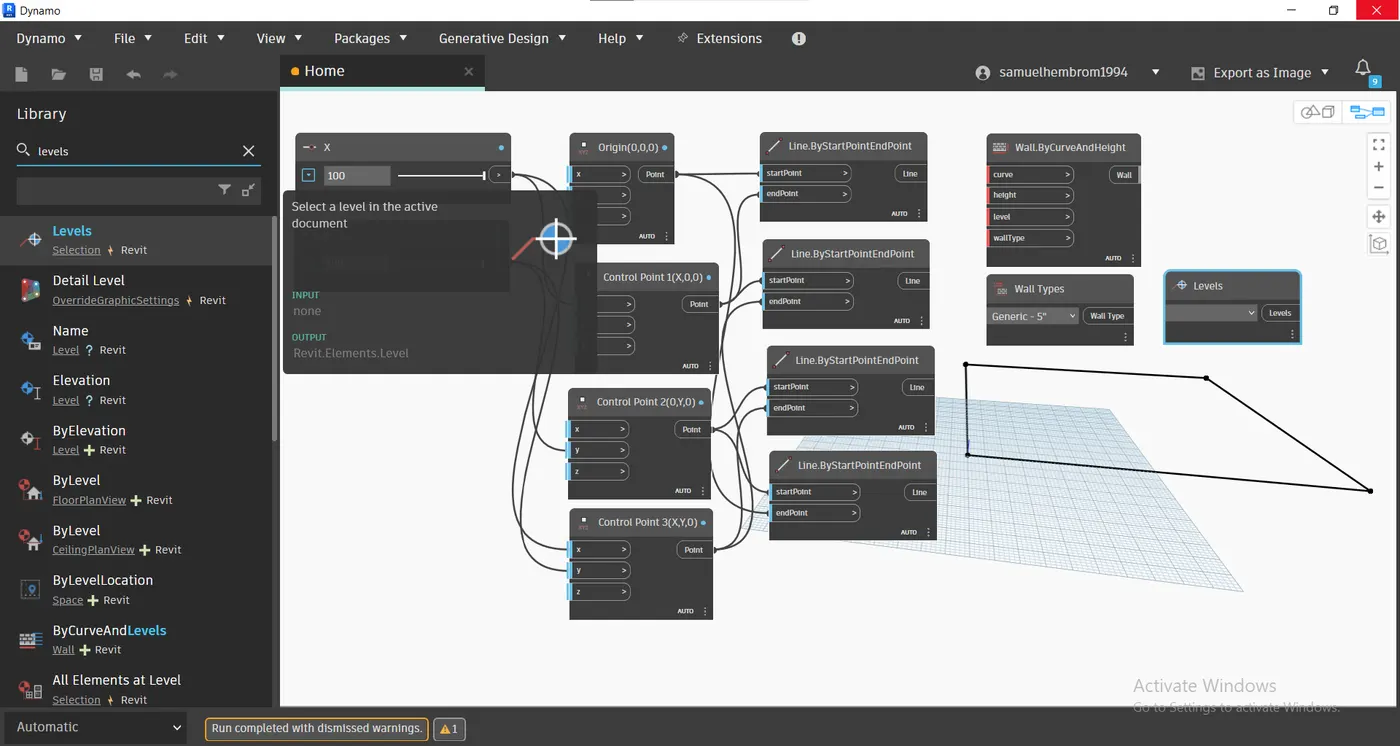
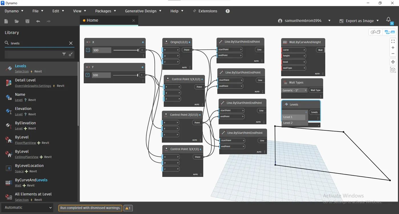
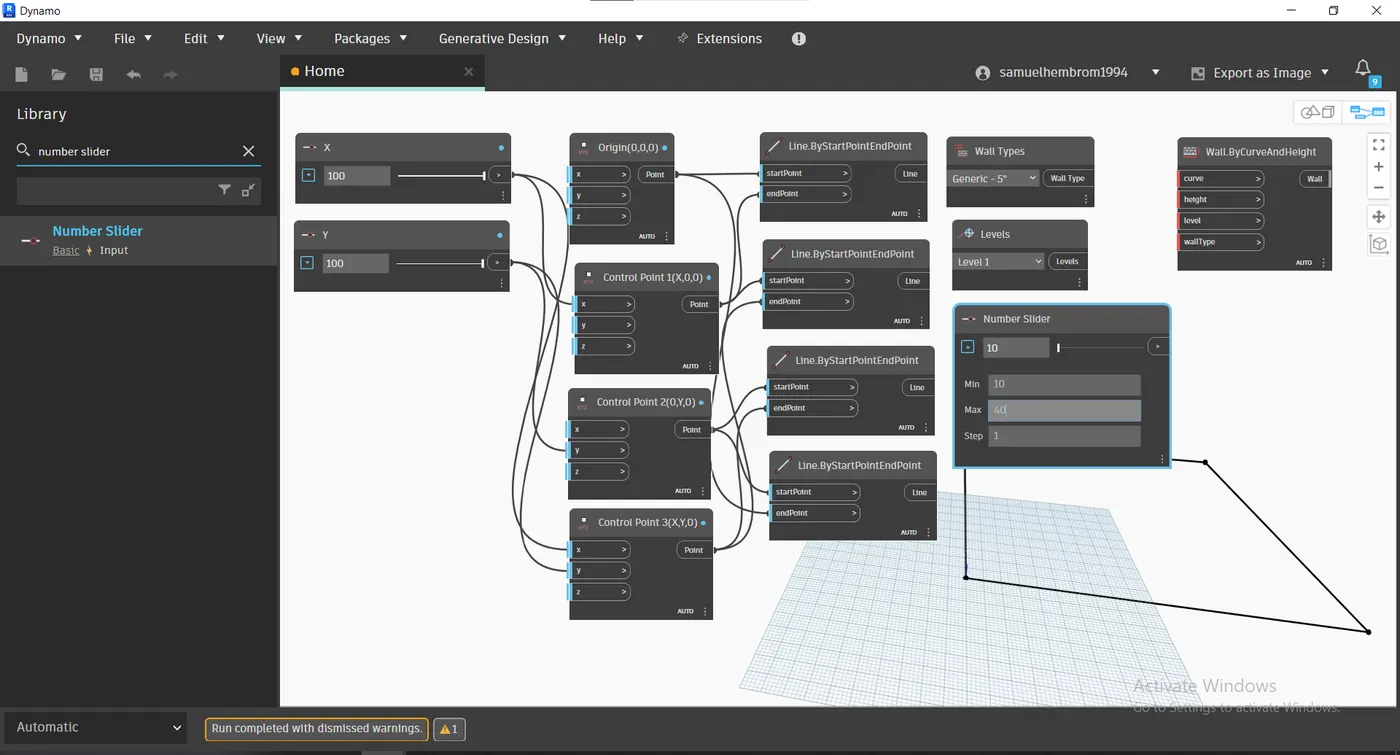
- In order to complete the wall we need to connect the lines to the list option.
- So search for "List" in search bar in "Library".
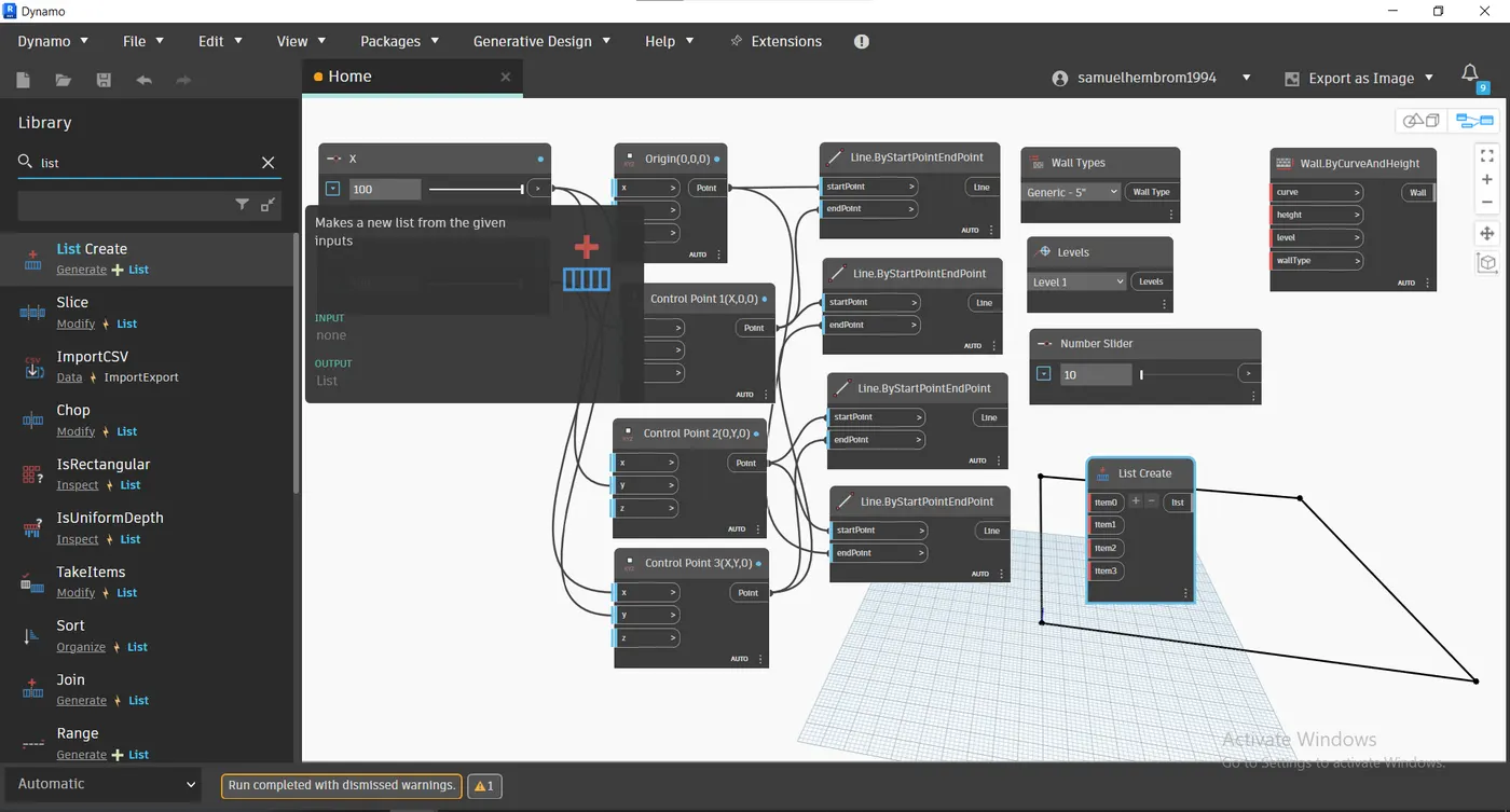
- Connect the "Lines" block to the "List" block & connect the "List" block to "Curve" option in "WallbyCurveandHeight" block.
- Similarly connect the "Number Slider" renamed as "Height" to the "Height" option of "WallbyCurveandHeight".
- Do the same for "Levels" and "Wall Types" curve block.
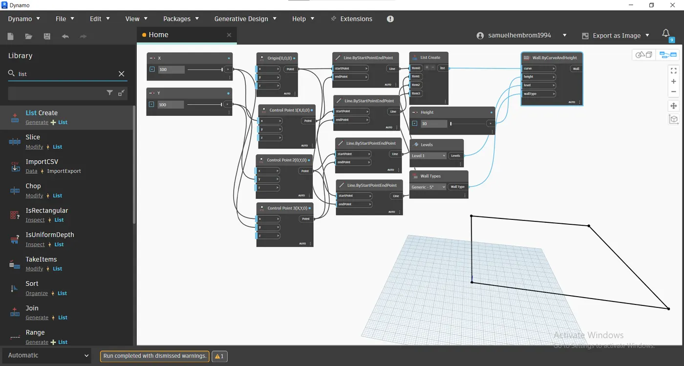
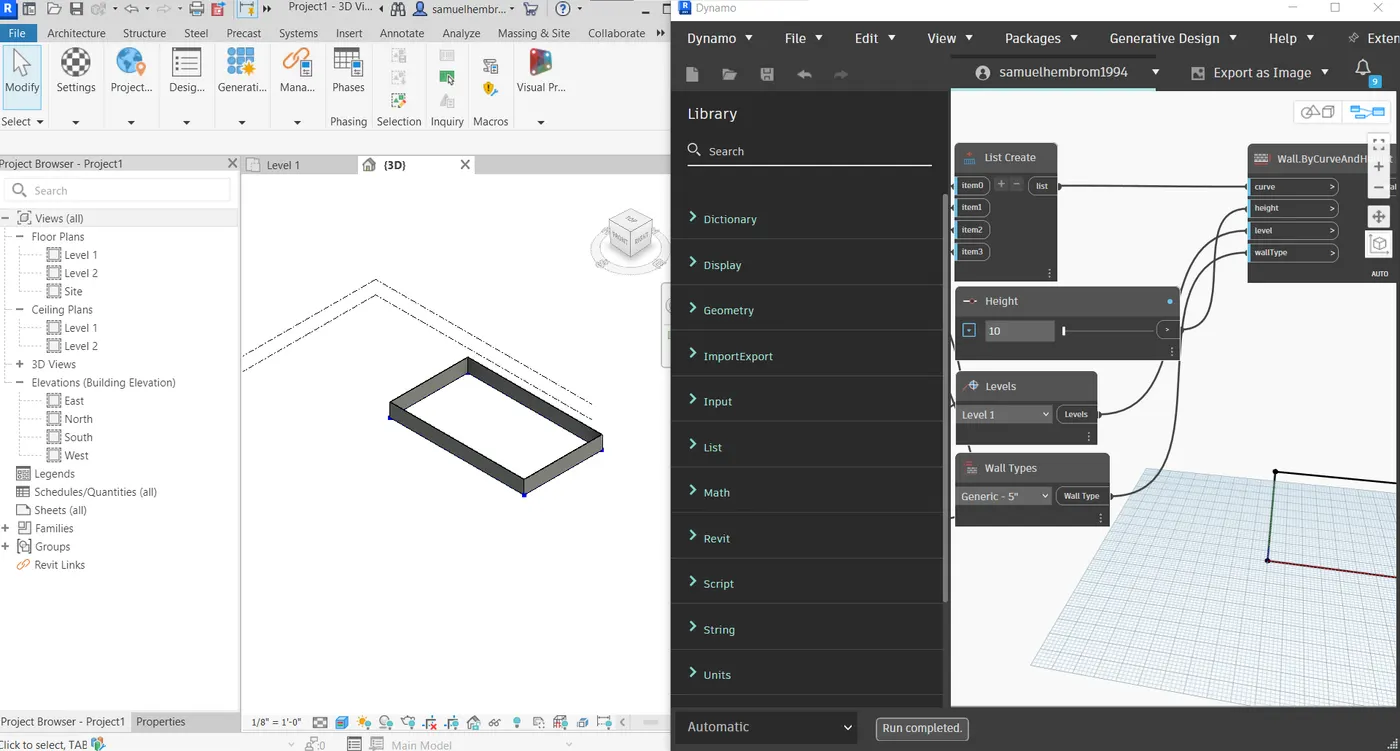
- Split the screen in two so that we can see both "REVIT" and "DYNAMO" screen simultaneously.
- In the Revit screen we can see a wall element has been created.
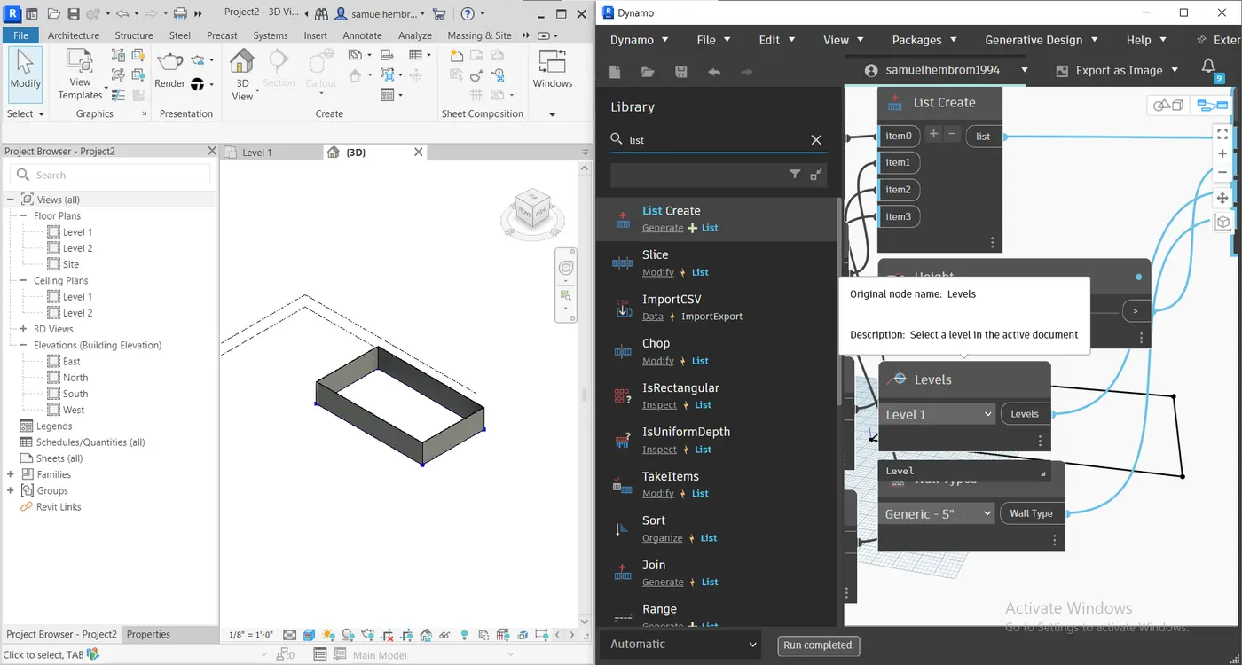
Result:-
So we have created a wall of height 10' and type Generic 5".
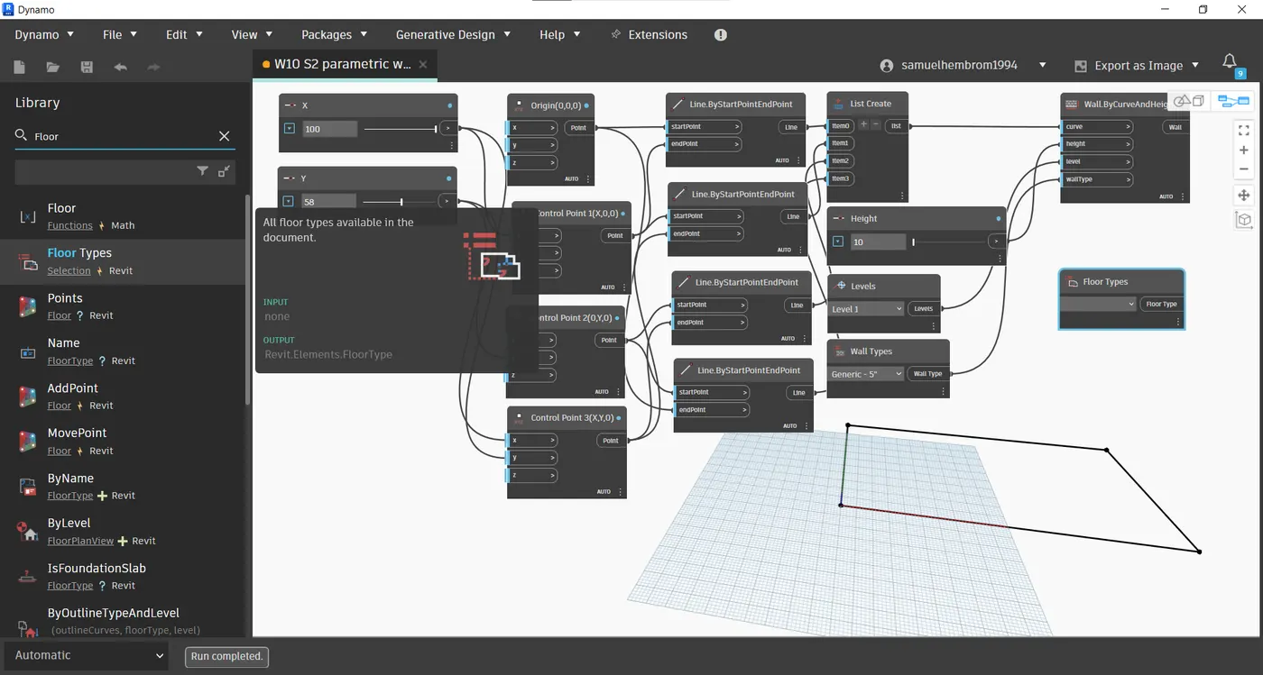
- In order to create "Floor" in Dynamo go for "Floor Type" option in search bar.
- Again go for the Floor "ByOutlineTypeAndLevel" option.
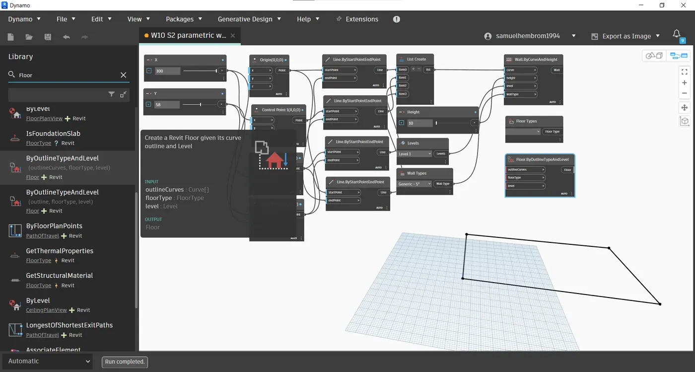
- Add the "List Create" block to the "outlinecurves" of the "Floor" block.
- Similarly choose suitable floor type from the drop down menu of the "Floor Type" block and join it to the "Floor" block as well.
- Again join the "Level" block to the "Level" option of the "Floor" block.
- So split the screen so that we can see both the dynamo and revit option.
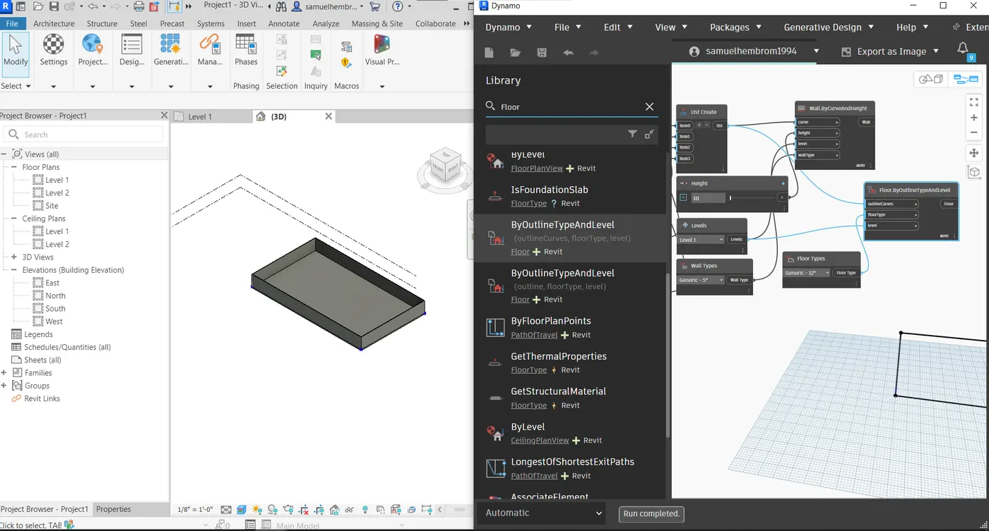
Final Result:-
So we have created the wall and floor with suitable level and height and material type.
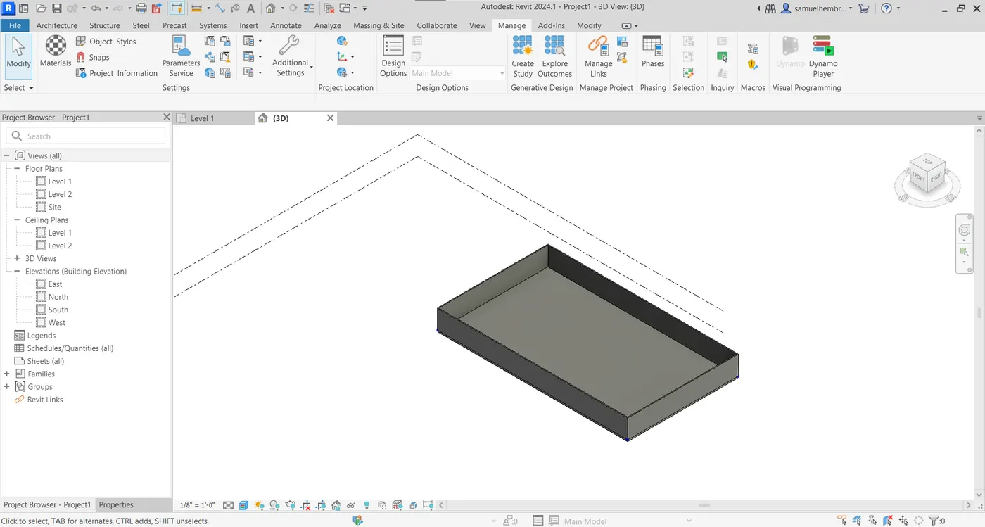
Q No.3
Ans:-
AIM:-
To create an array of model elements in Revit.
Procedure:-
- Open the Revit Software.
- Open a new architectural template.
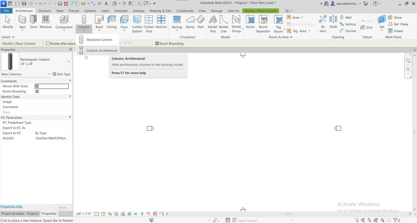
- Go to Architecture -> Create -> Column -> Column : Architectural.
- Place the column in the model space.
- From the properties browser select the "Rectangular Column" of 24" X 24".
- Set the base level to Level 1 and top level to Level 2.
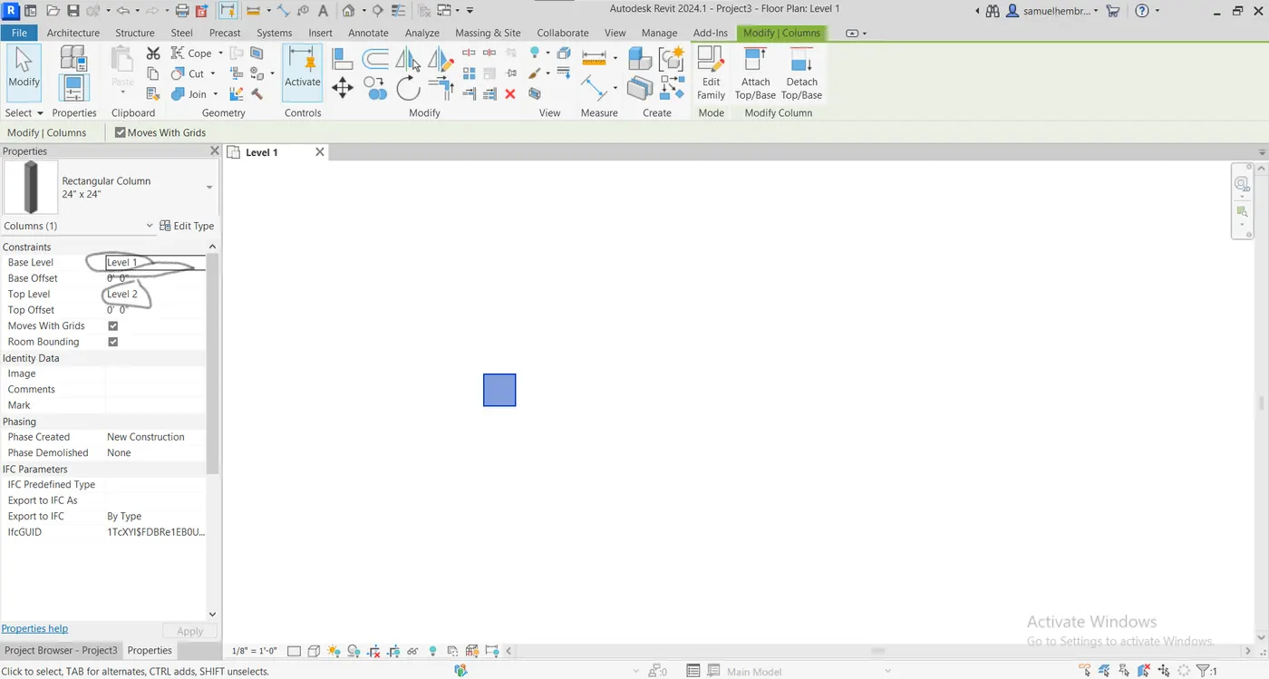
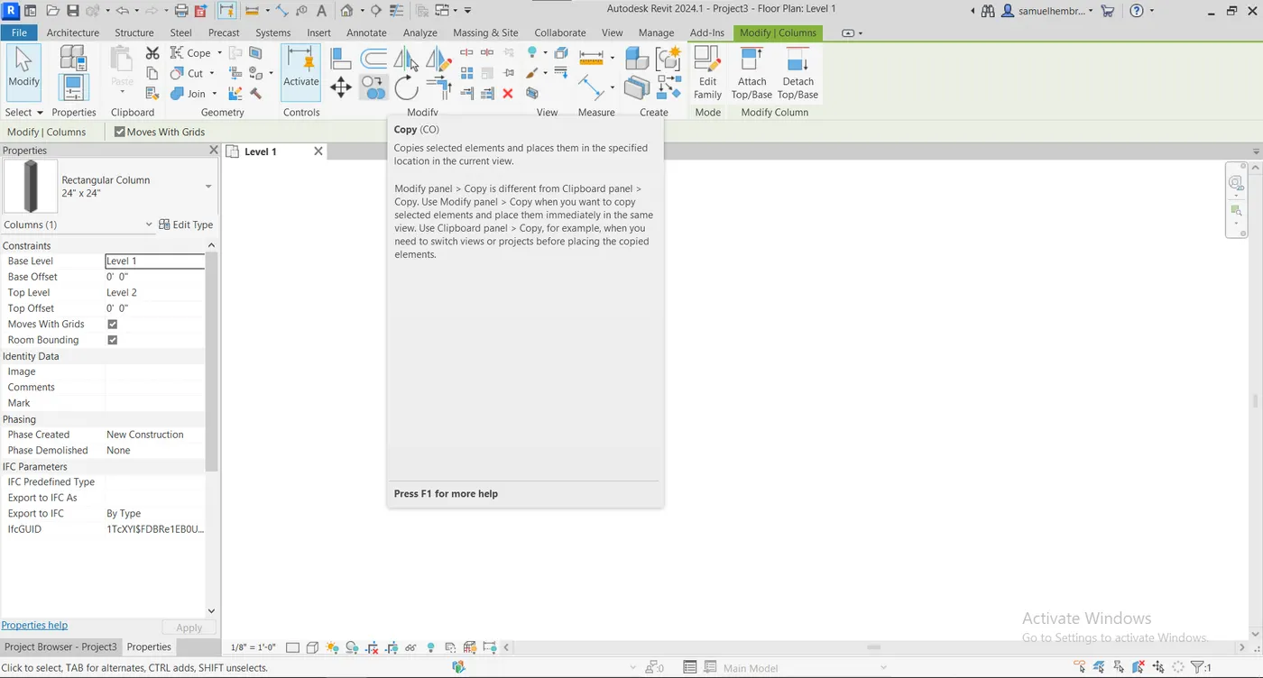
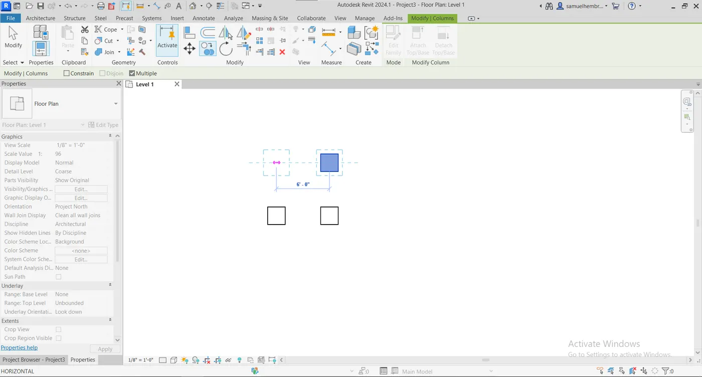
- Go to Modify/Column -> Modify -> Copy.
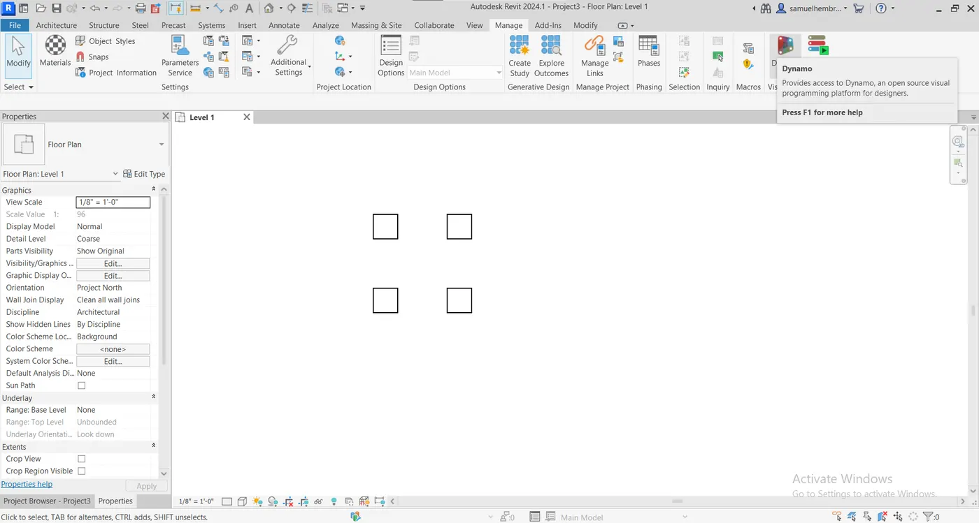
- Select above drawn column and copy it so that we have four columns 6' apart from each other.
- Next go to Manage -> Visual Programming -> Dynamo.
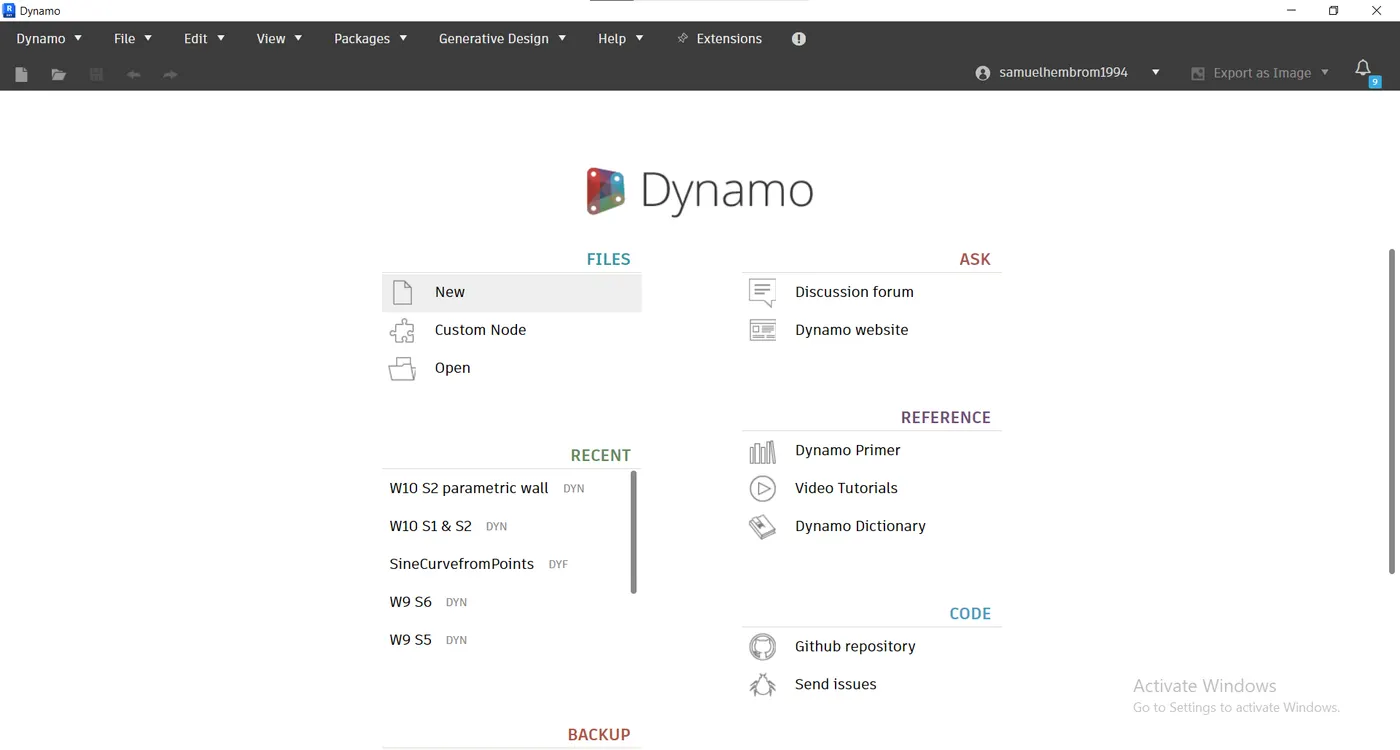
- Open a New file in Dynamo.
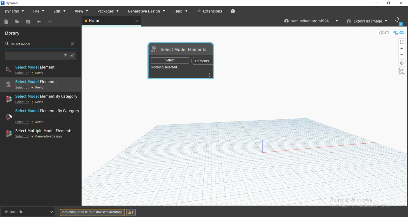
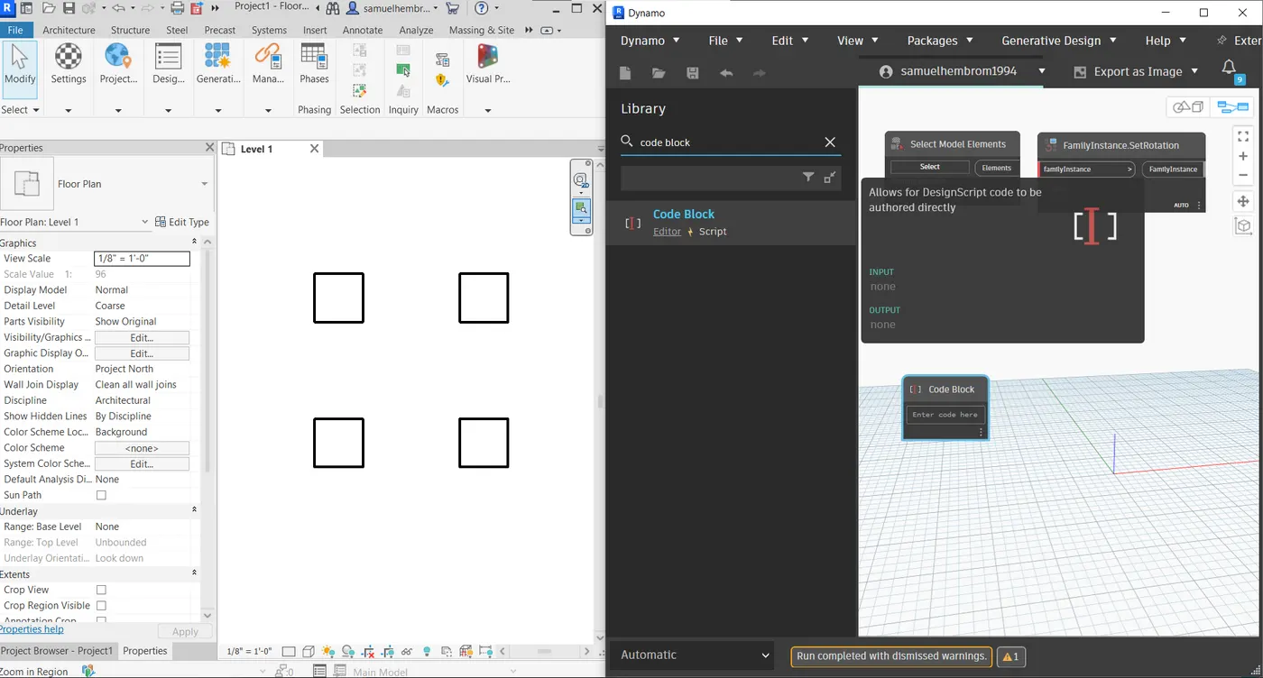
- In the search bar of the Library search for "Select Model", "Set Rotation", and "Code Block".
- Split the screen so that we can see both the model space of dynamo and revit simultaneously.
- Rename the "Code Block" to "Angle degree" and provide the value of 45 unit.
- In the "Select Model Elements" block click on select button and select the columns in the revit workspace.
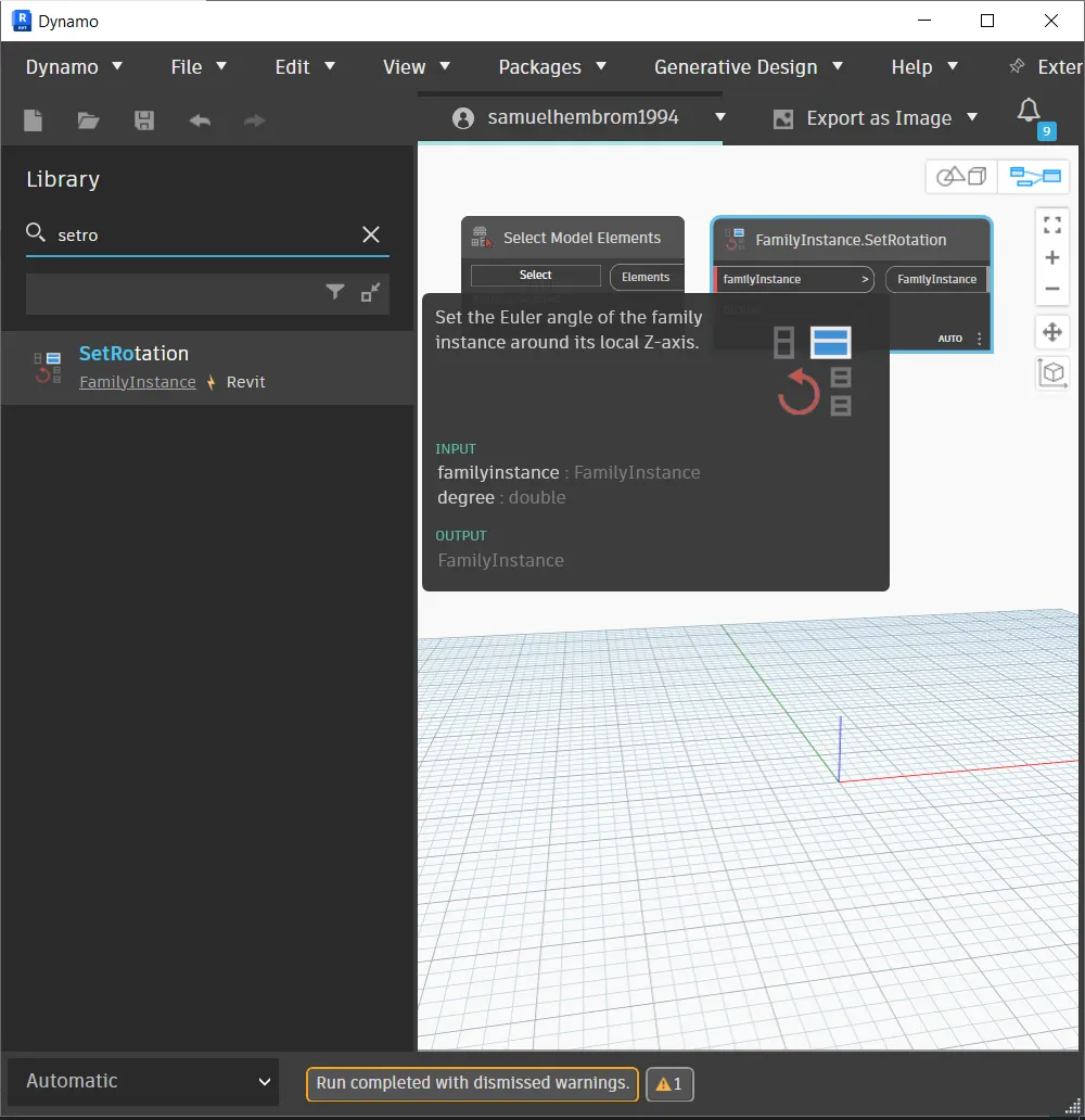
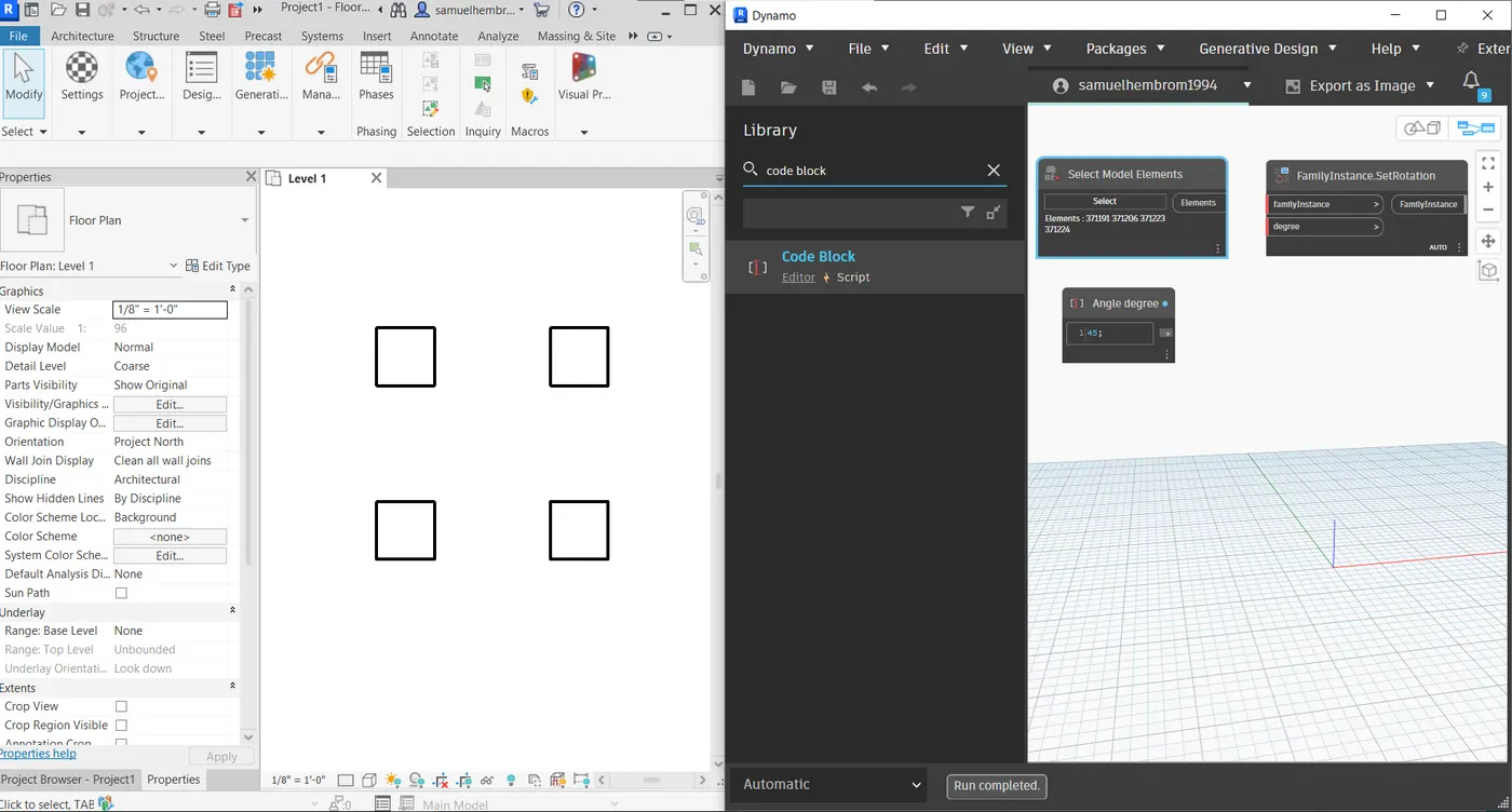
- Join the "Mode Elements" block to "Set Rotation" block and do the same for "Angle Degree" block.
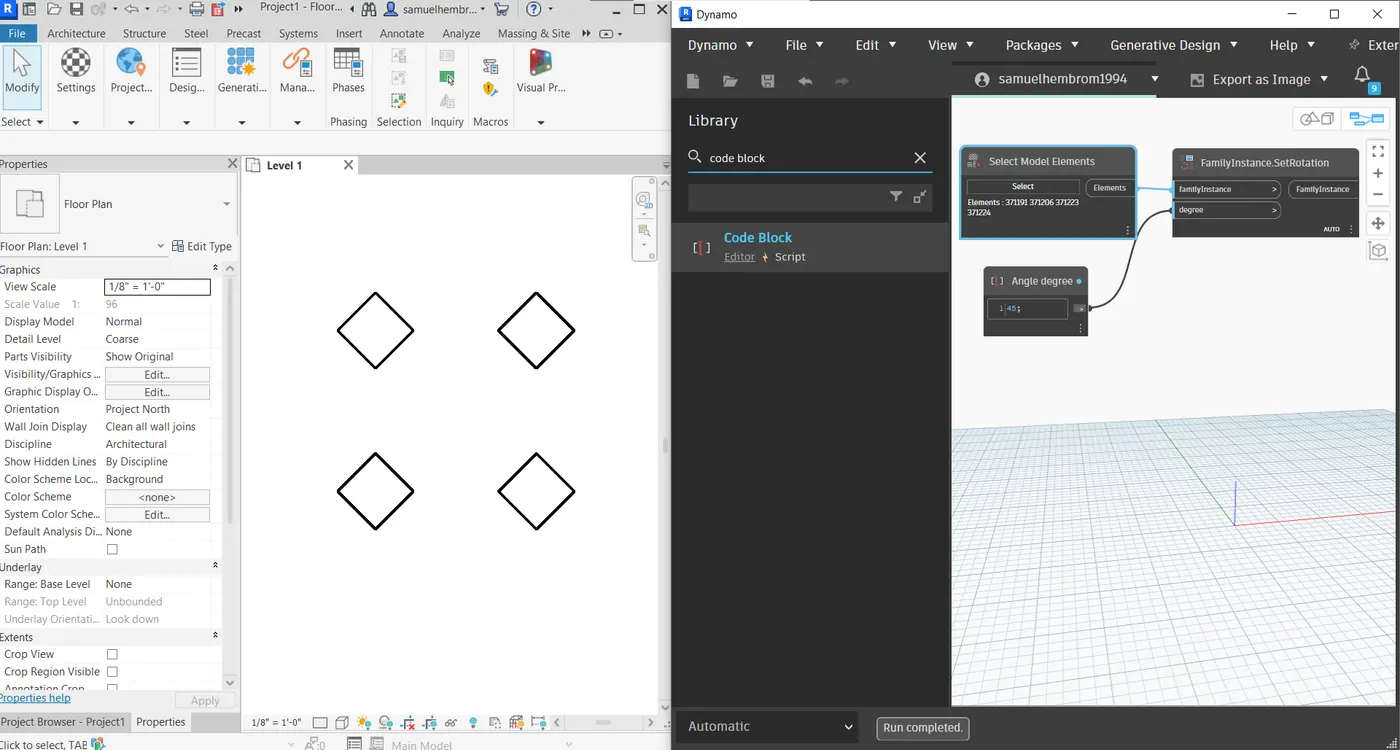
- We can see in the above diagram that columns have been rotated at an angle of degrees.
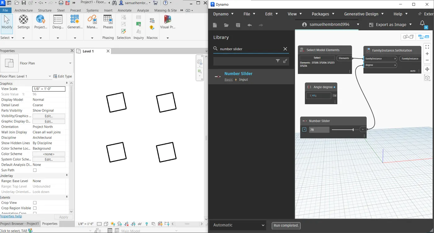
- We can use the Number slider as well for the degree option in the "FamilyInstance.SetRotation" block.
- Search for Number slider in the search bar in library and add a number slider in the workspace.
- Set the minimum and maximum values as 30 to 90 respectively.
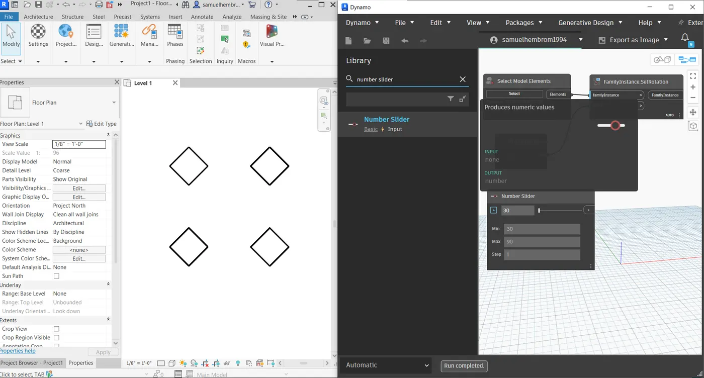
- As we slide through the values we will observe that the columns in revit workspace are rotating as well.
Q No.4
Ans:-
AIM:-
To create a conceptual mass in REVIT and develop a parametric column by dividing the surfaces.
Procedure:-
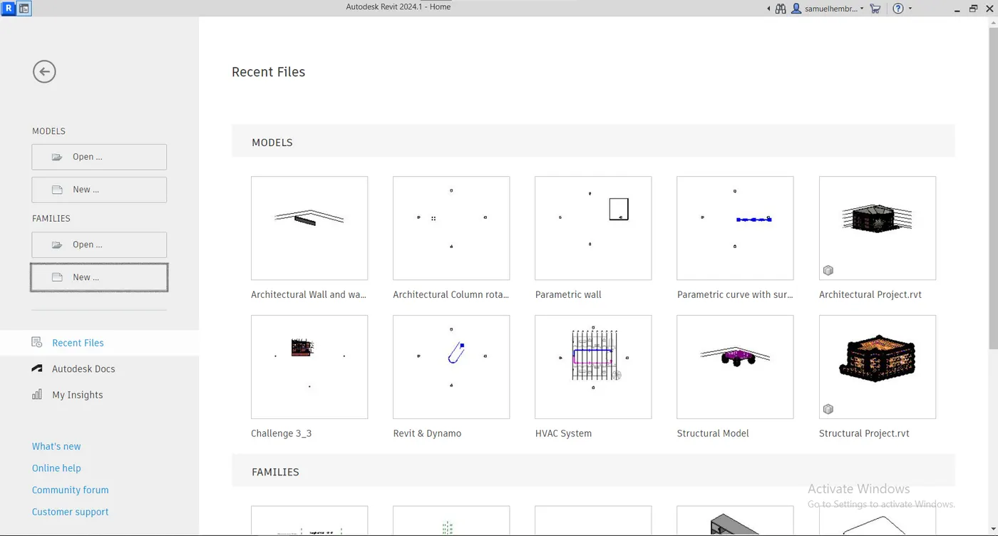
- Open Revit software and click on "New" button under the "Family" section.
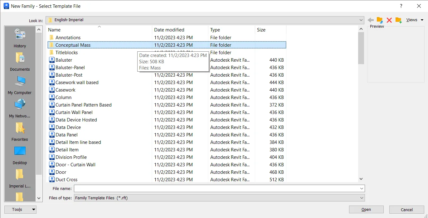
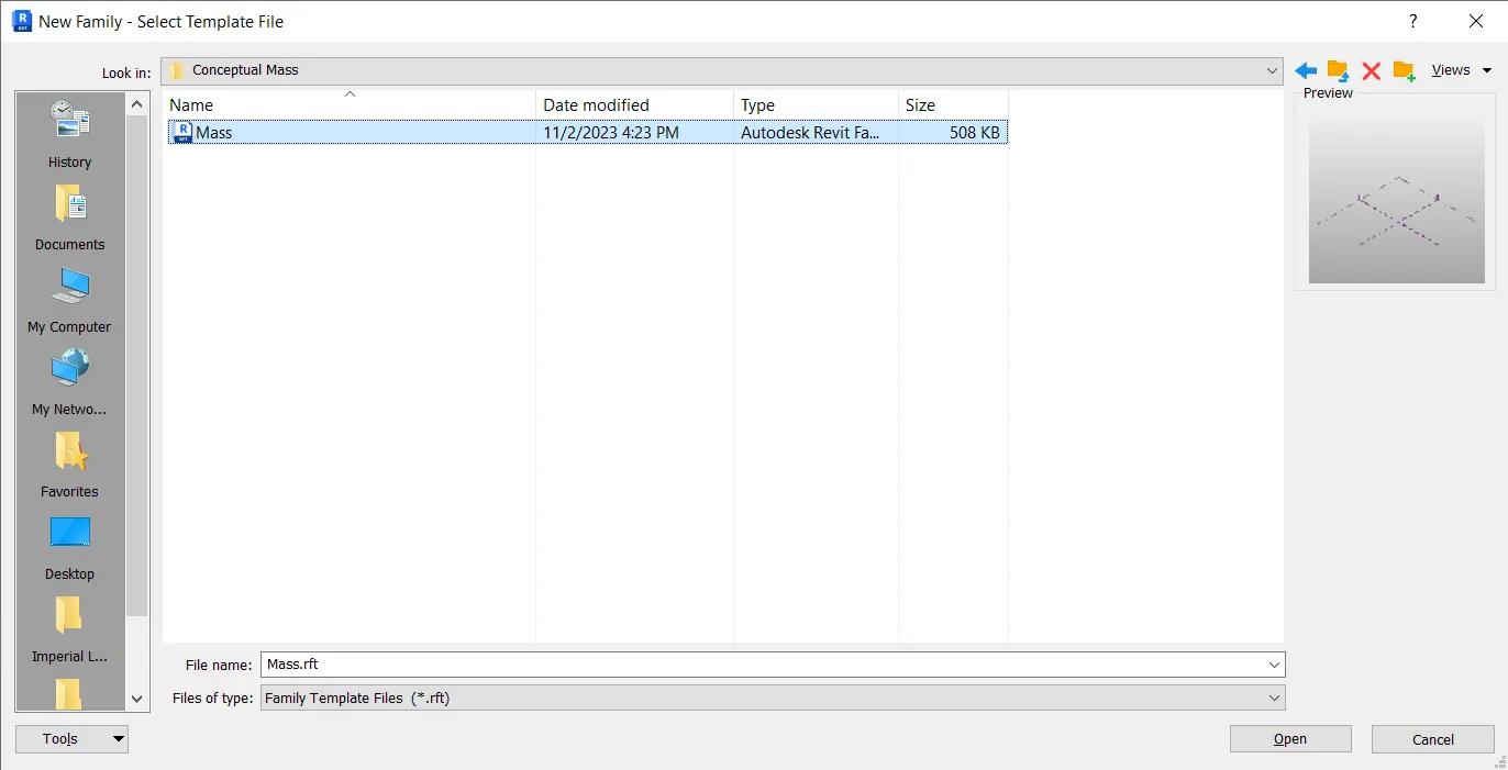
- In the New Family-Select Template File go for the "Conceptual Mass" folder and select "Mass".
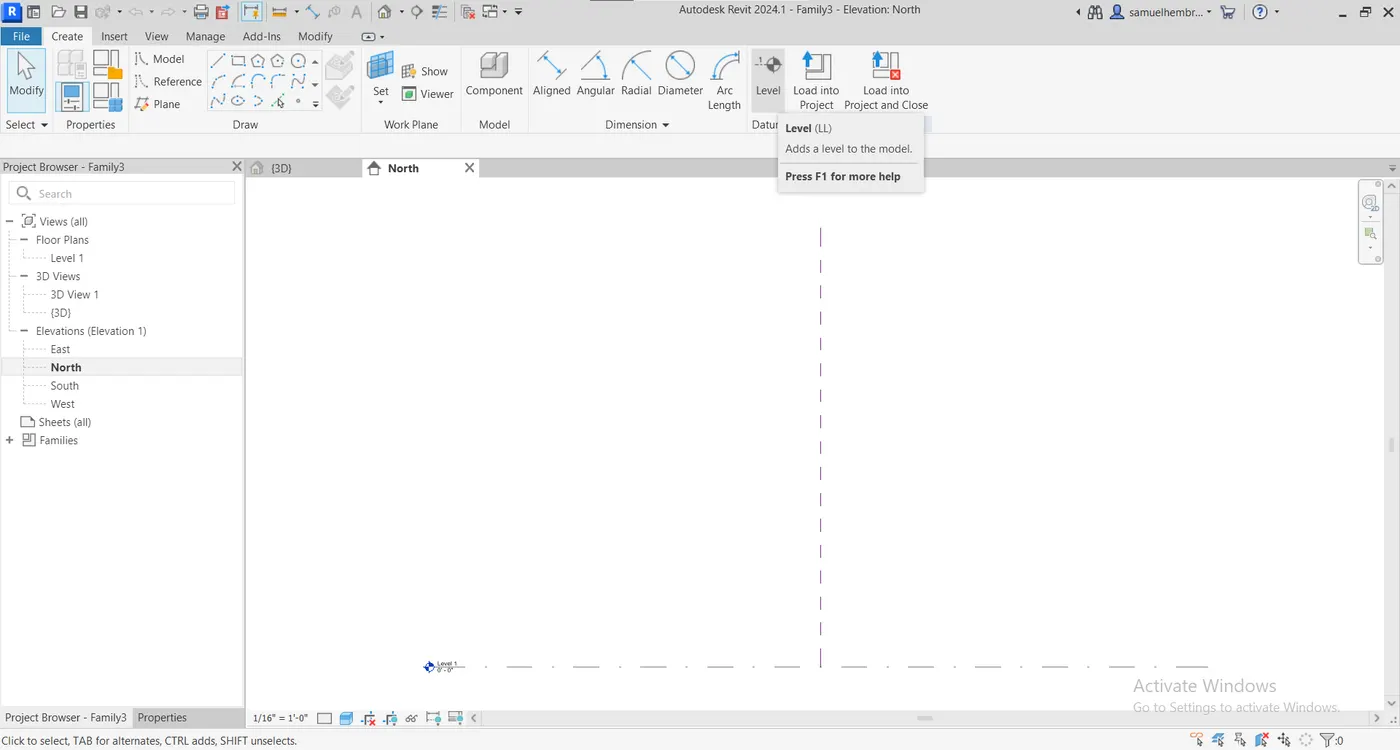
- Open a elevation view.
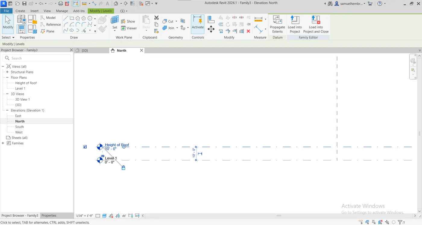
- Now go to Create -> Datum -> Level.
- Draw a level at a height of 10' and name it as "Height of Roof".
- Now go to "Height of Roof" floor plan.
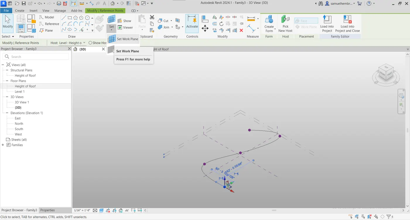
- Now go to Modify -> Work plane -> Set -> Set Work Plane.
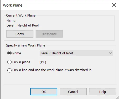
- "Work Plane" tab will open. Just click on "OK" button and leave the parameters to its default value.
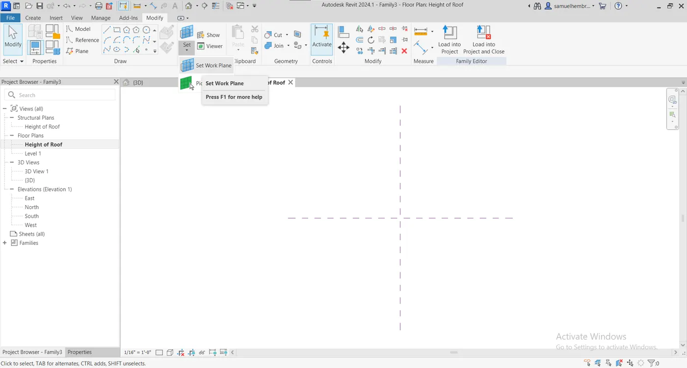
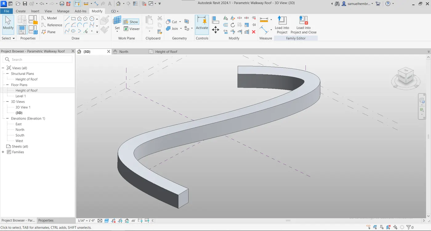
- Now go to Modify -> Draw -> Spline through points.
- Place the points on the work plane so that it forms a curve as shown in image below.
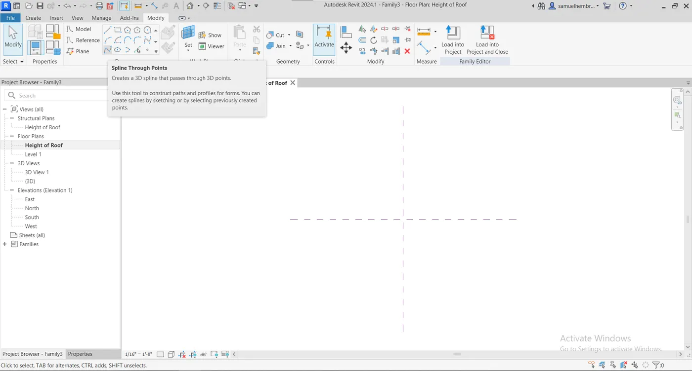
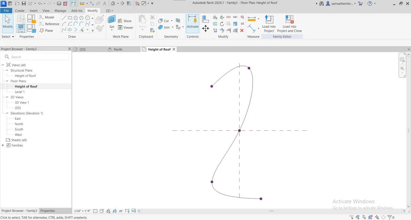
- Go for the 3D model.
- Go to Modify/Reference Point -> Work Plane -> Set -> Set Work Plane.
- Select an end point of the curve.
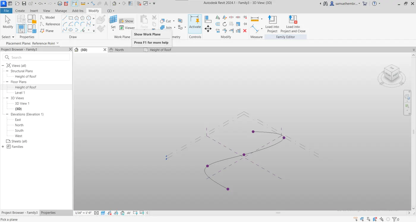
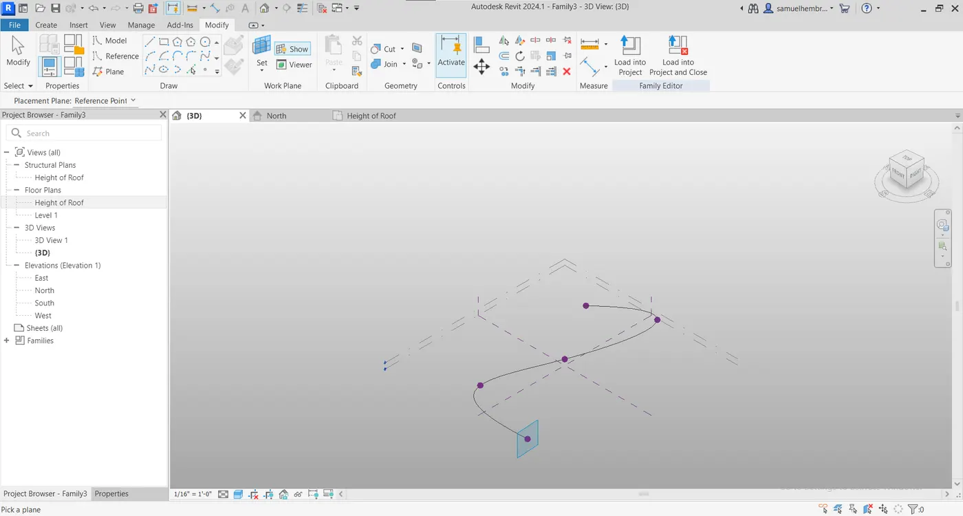
- Go to Modify -> Work Plane -> Show.
- We can see that a plan is made at the end point of the curve.
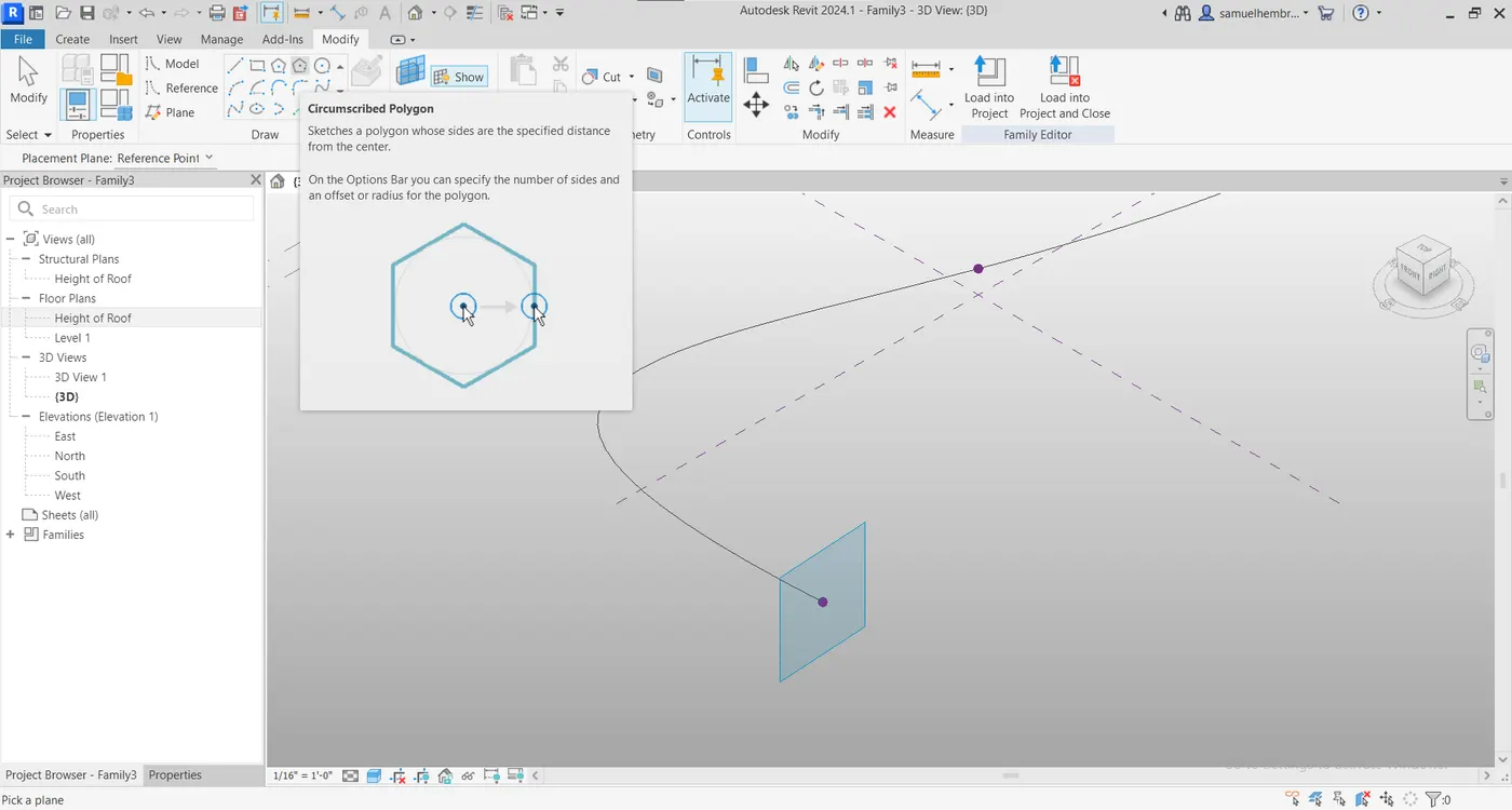
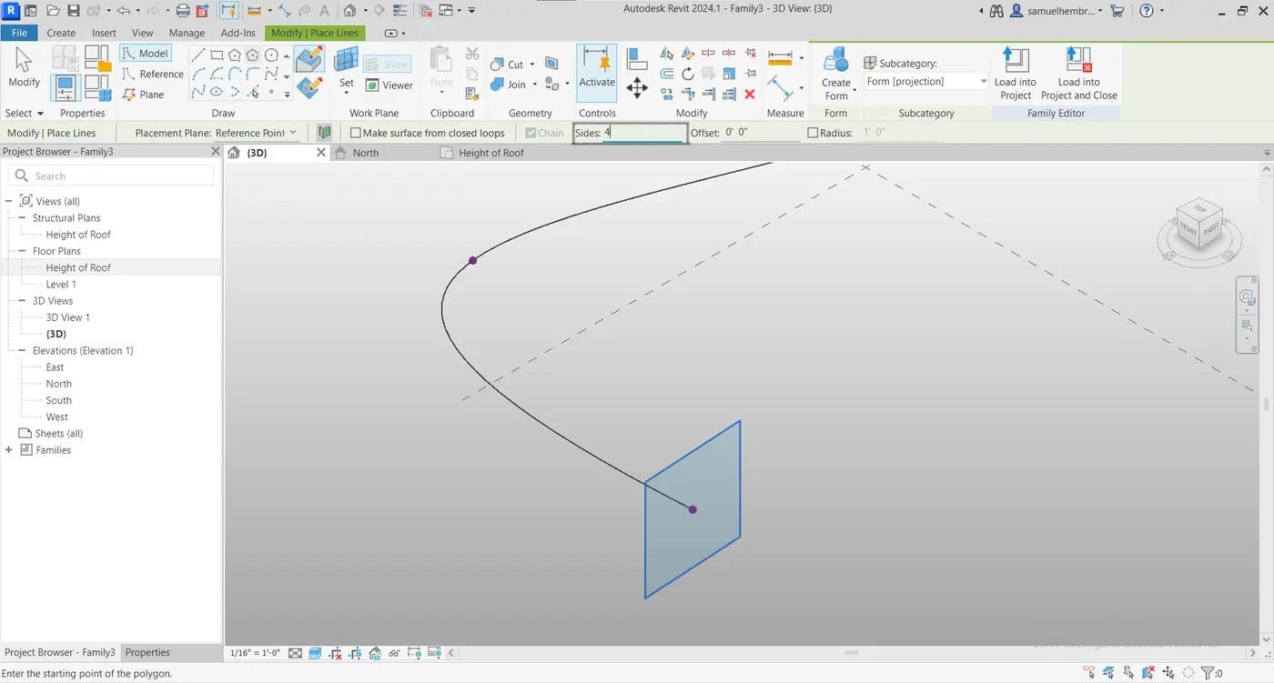
- Go to Modify -> Draw -> Circumscribed Polygon.
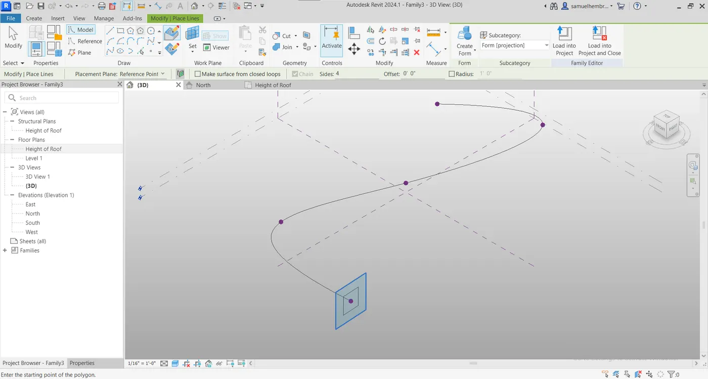
- In the "Modify/Place Lines" ribbon select Sides=4.
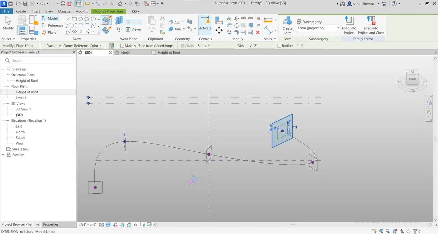
- Similarly do the same for all the control points.
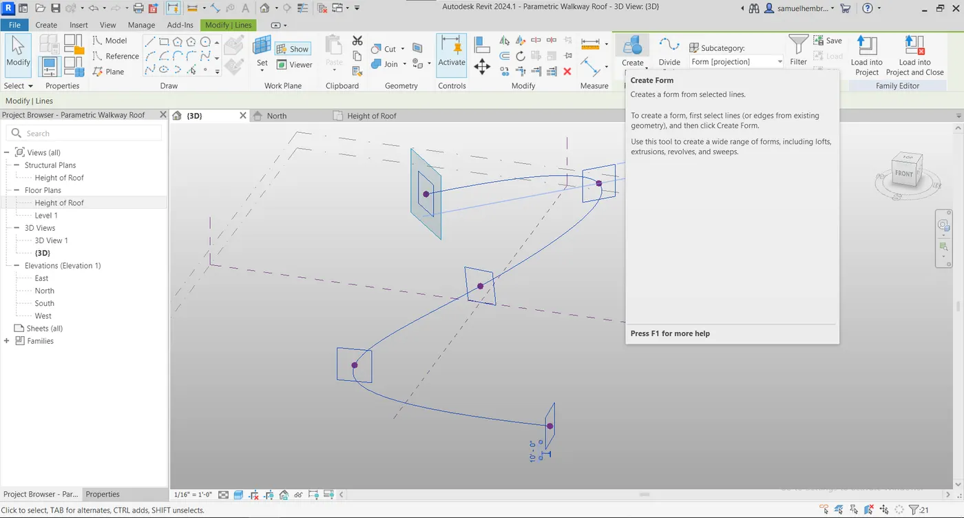
- Next the curve and reference points and go to Modify/Lines -> Forms -> Create form.
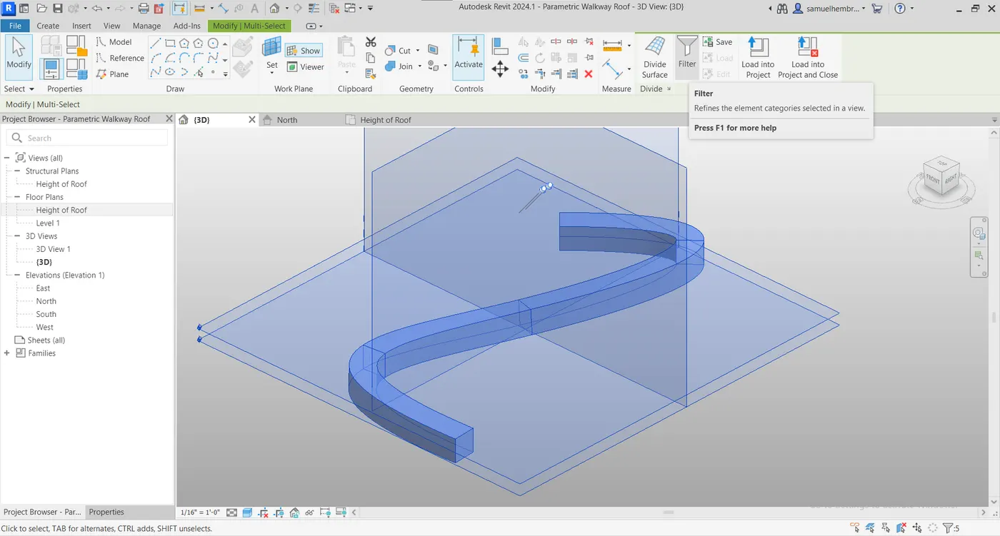
- Next select the curve and go to Modify/Multi-Select -> Selection -> Filter.
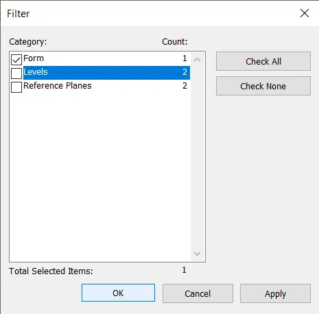
- In the "Filter" dialogue box uncheck all the elements except "Form" and click "OK".
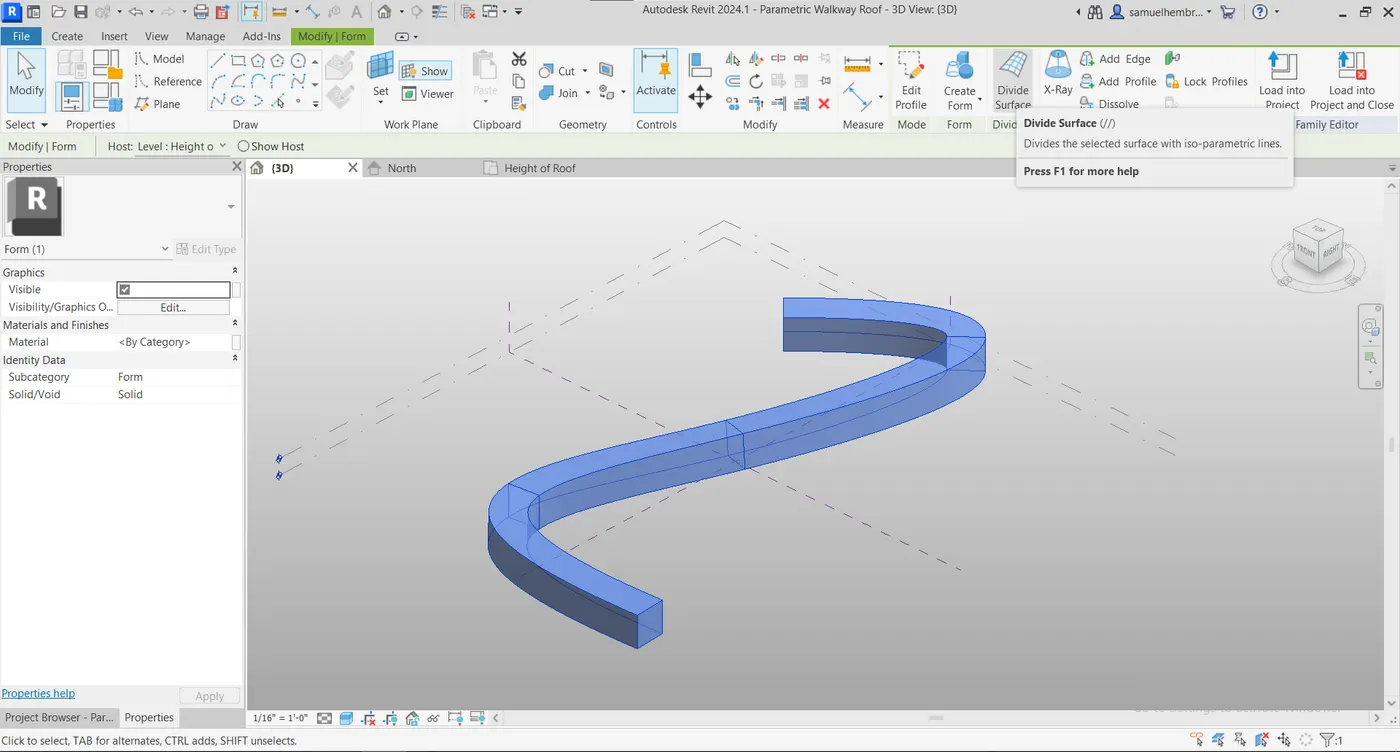
- Next go to Modify/Form -> Divide -> Divide Surface.
- In the properties browser select the "Triangle(bent)" pattern.
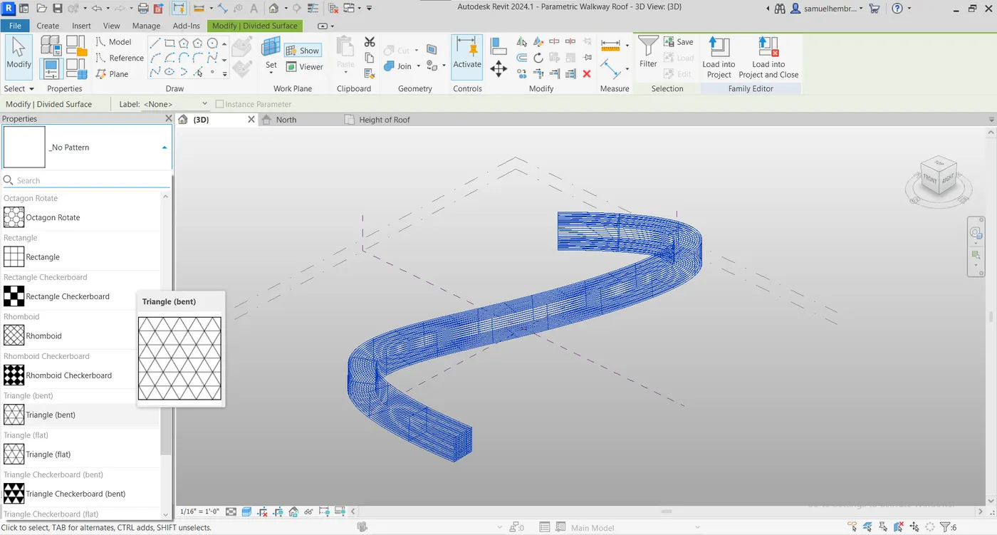
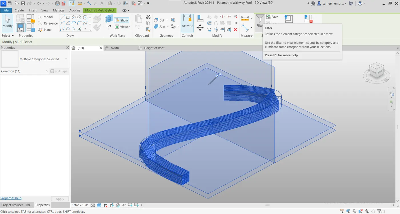
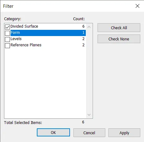
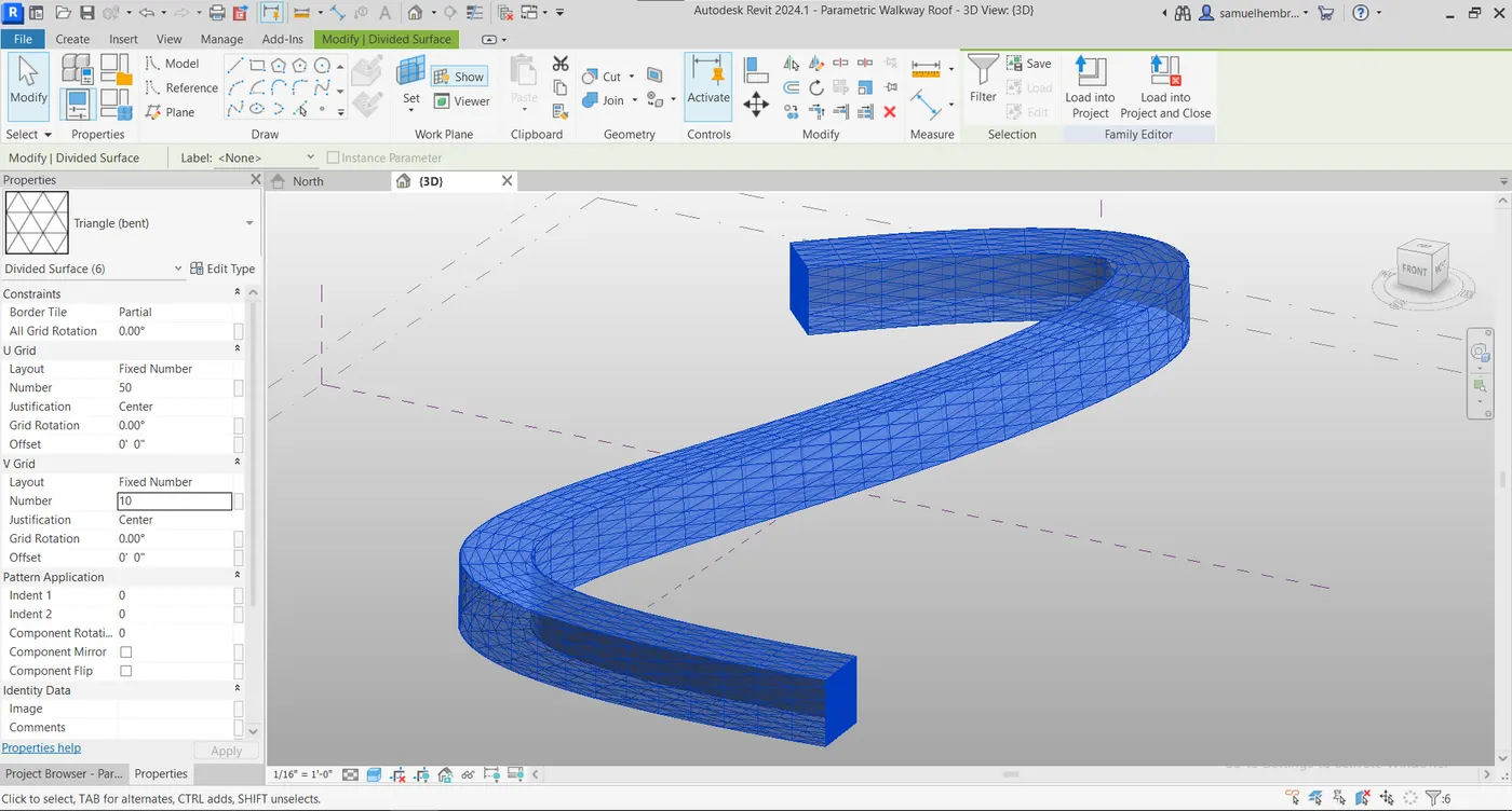
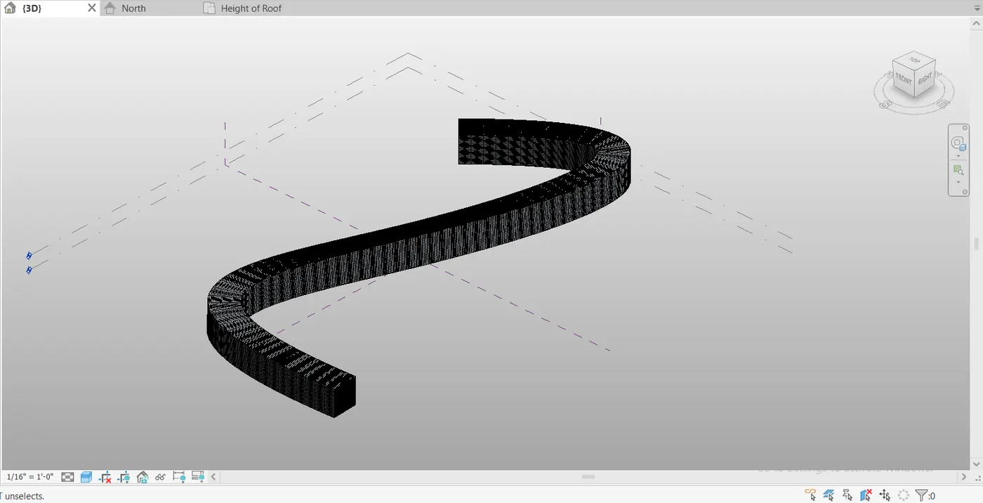
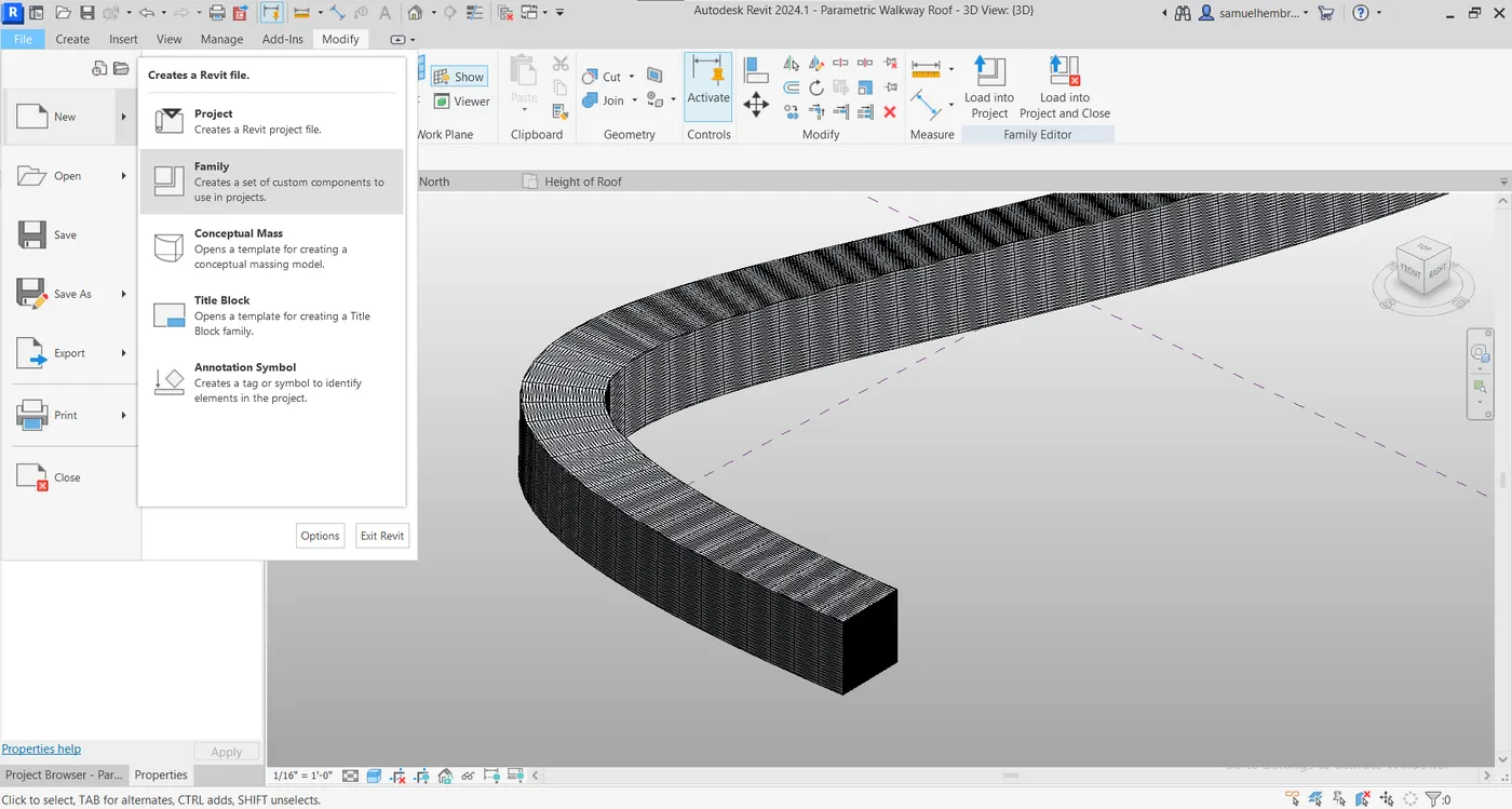
- Next go to "File" menu and create a new family.
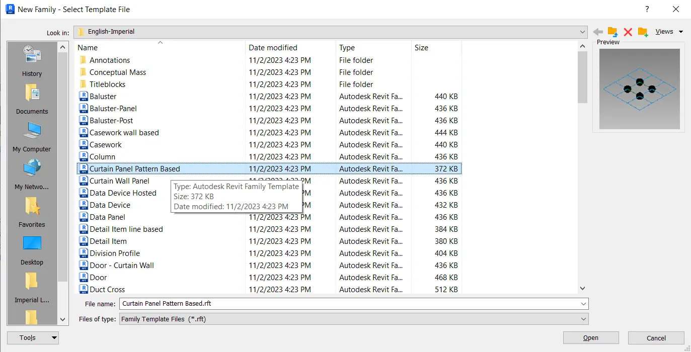
- In the "New Family - Select Template File" choose "Curtain Panel Pattern Based".
- Now from the properties browser select "Triangle(bent)"
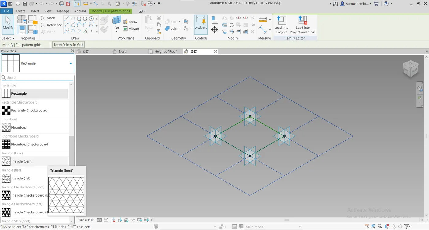
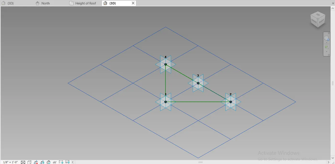
- Go to Modify -> Draw -> Reference line.
- Again go to Modify -> Draw -> Point Element.
- Select the mid-point of the line joining points 1 and 2.
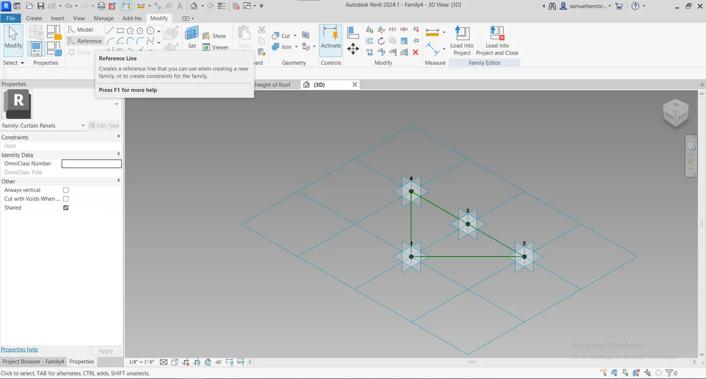
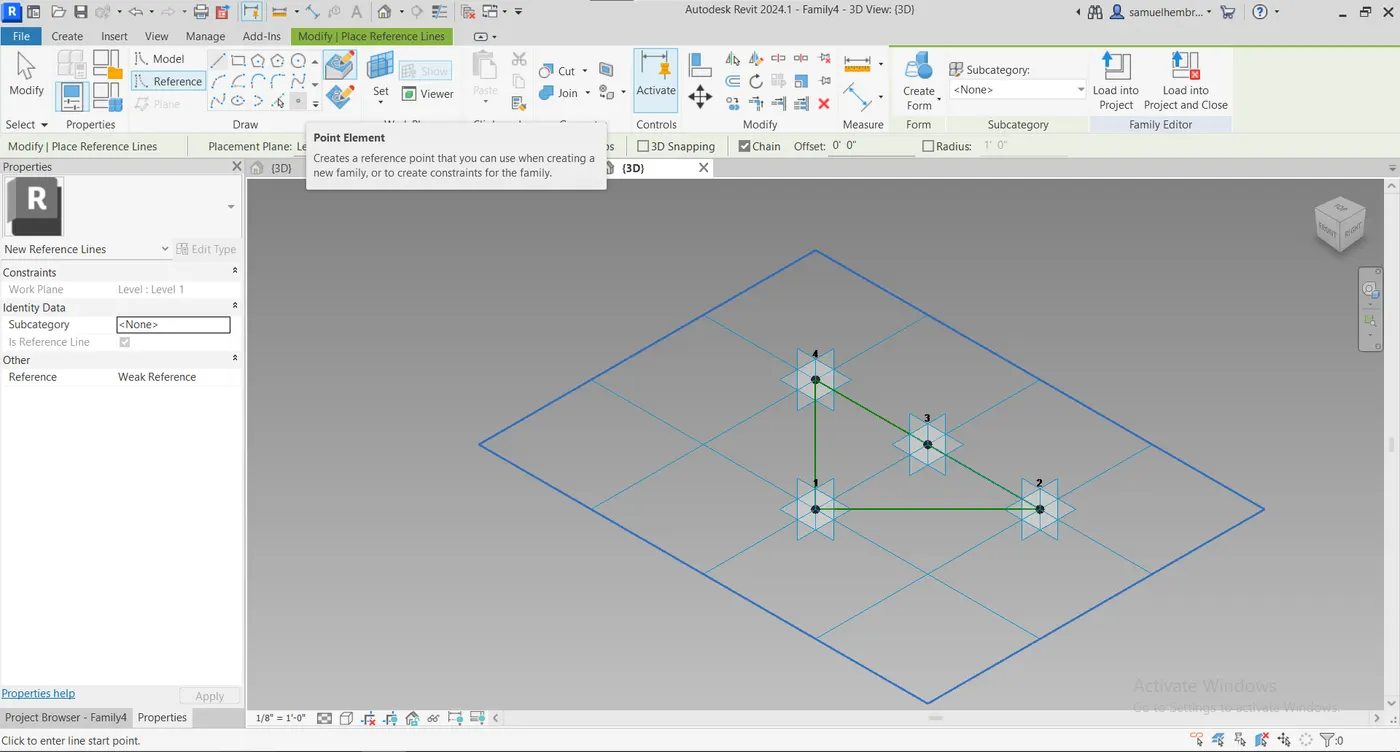
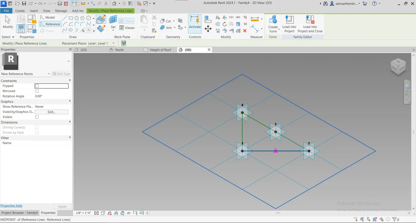
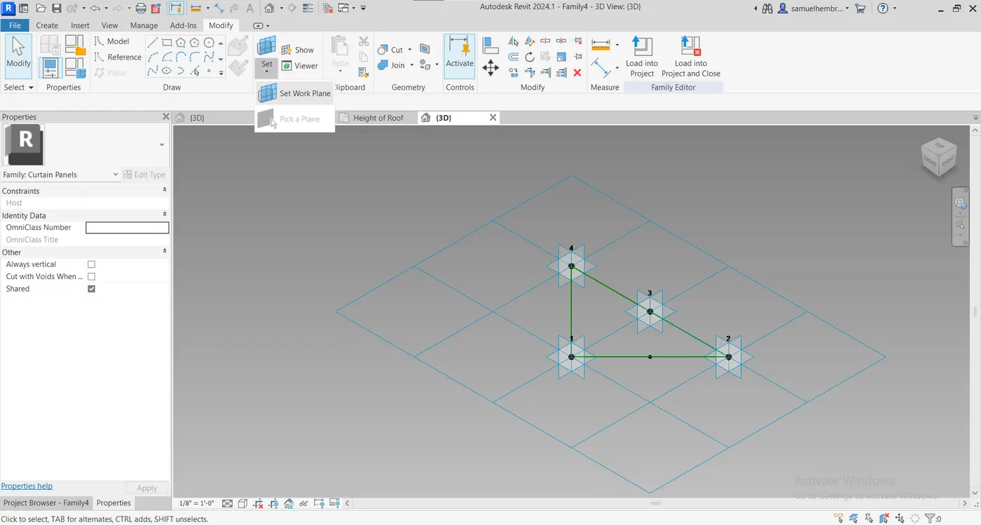
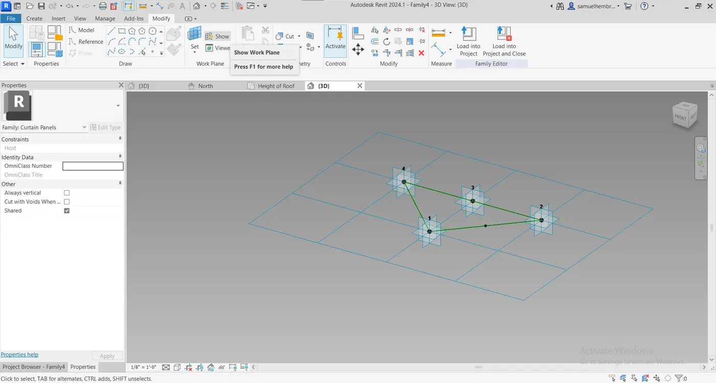
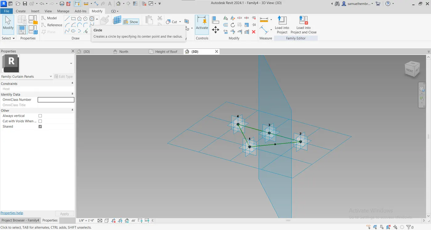
- Next go to Modify -> Draw -> Circle.
- Draw a circle of 2" on the point in which reference plane is created.
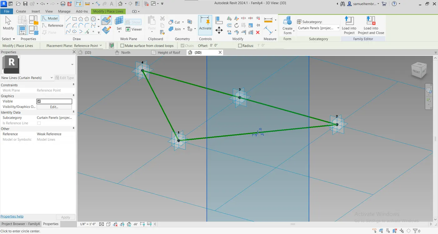
- Select the curve and circle.
- Go to Modify/Lines -> Form -> Create Form
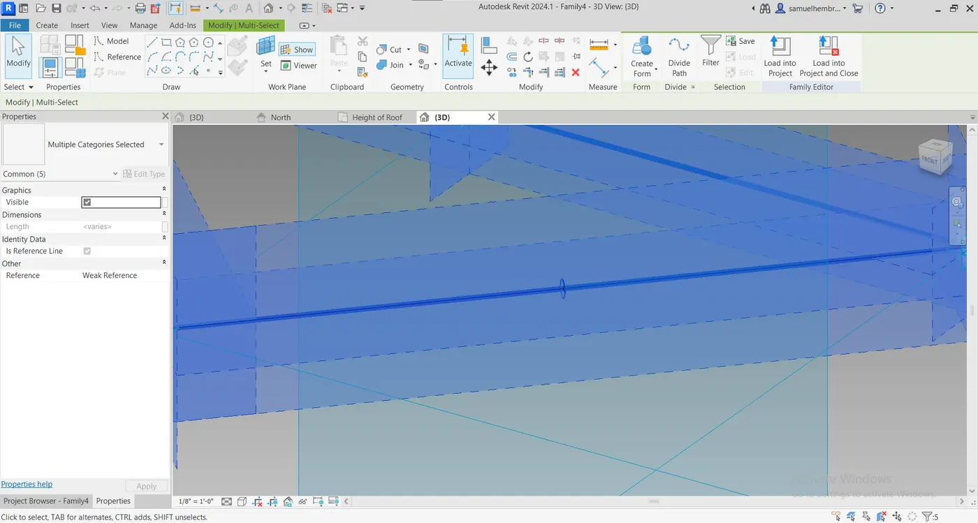
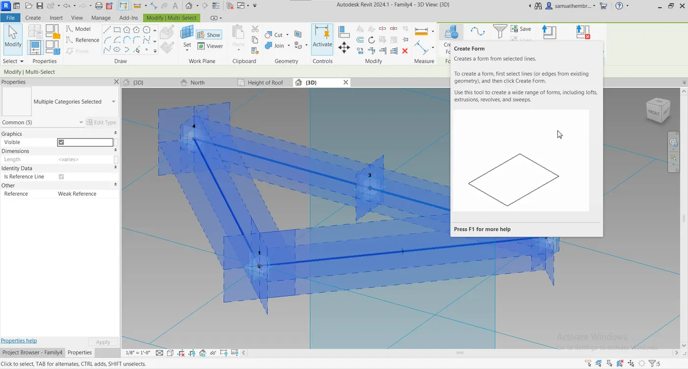
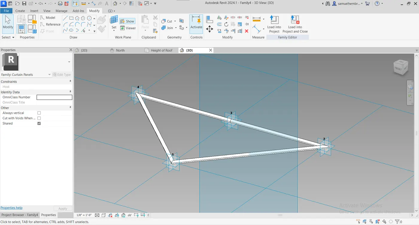
- Next go to Modify -> Family Editor -> Load into project.
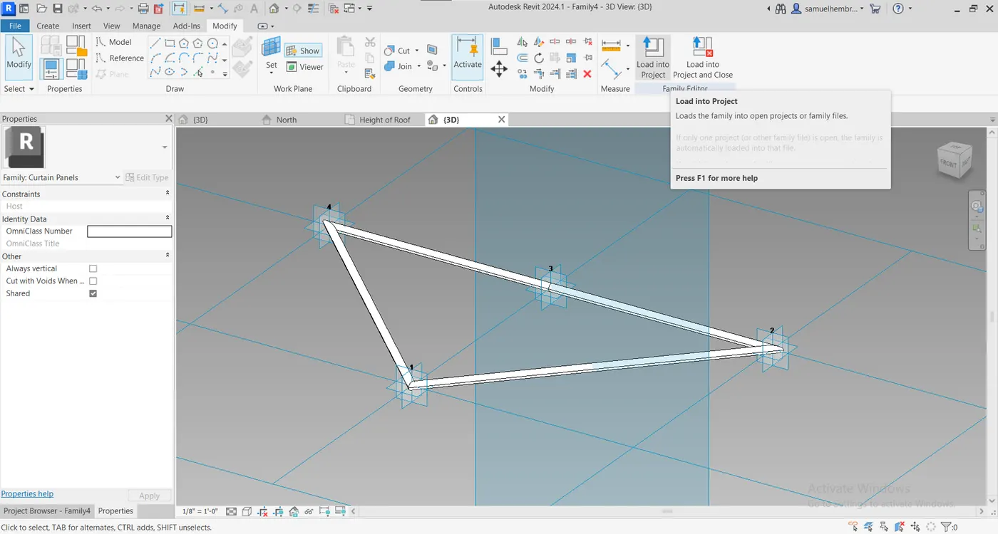
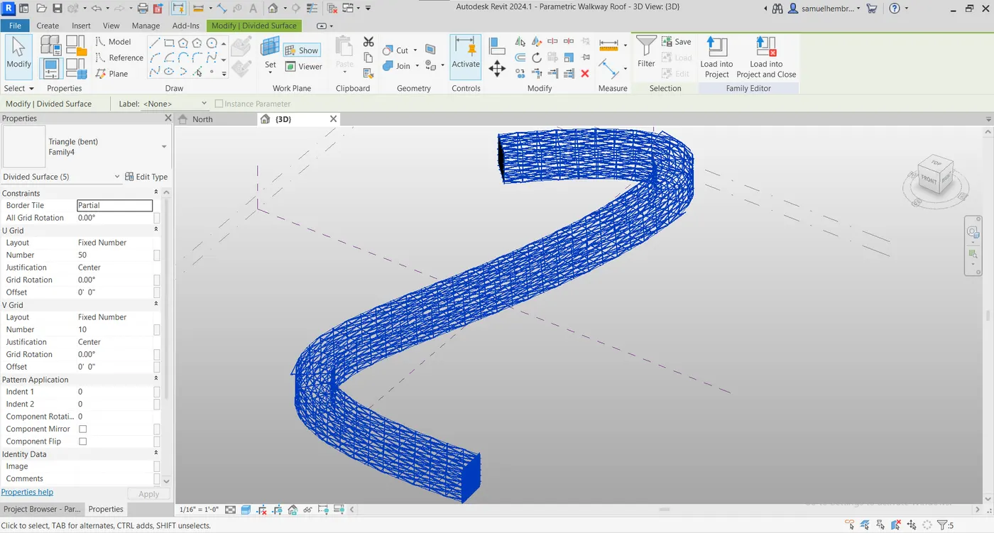
- In the parametric walkway roof template select the loaded family from the properties browser.
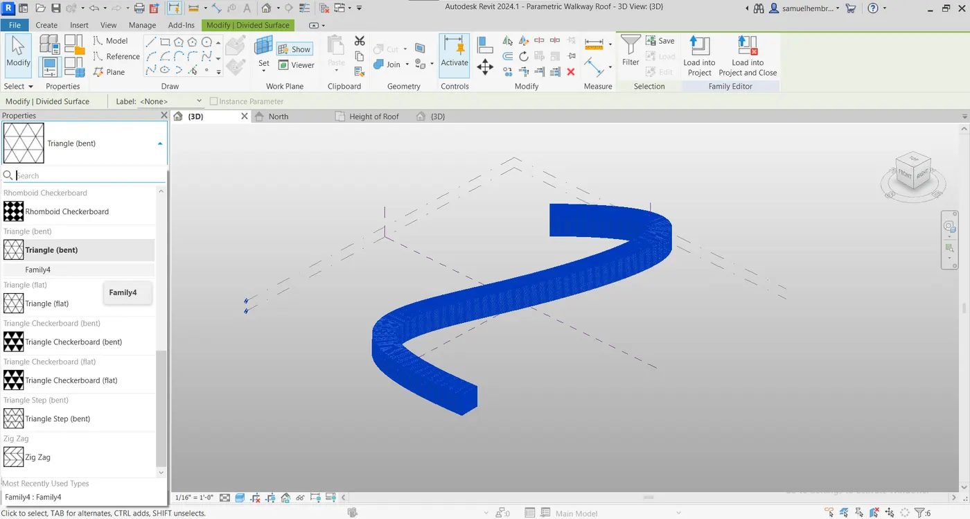
Final Result:-
We can see that conceptual mass have been created and in Revit and is as follows:-
Q No.5:-
Ans:-
AIM:-
To develop the Parametric Stadium using dynamo in Revit.
Procedure:-
- Go to Revit software and open Dynamo.
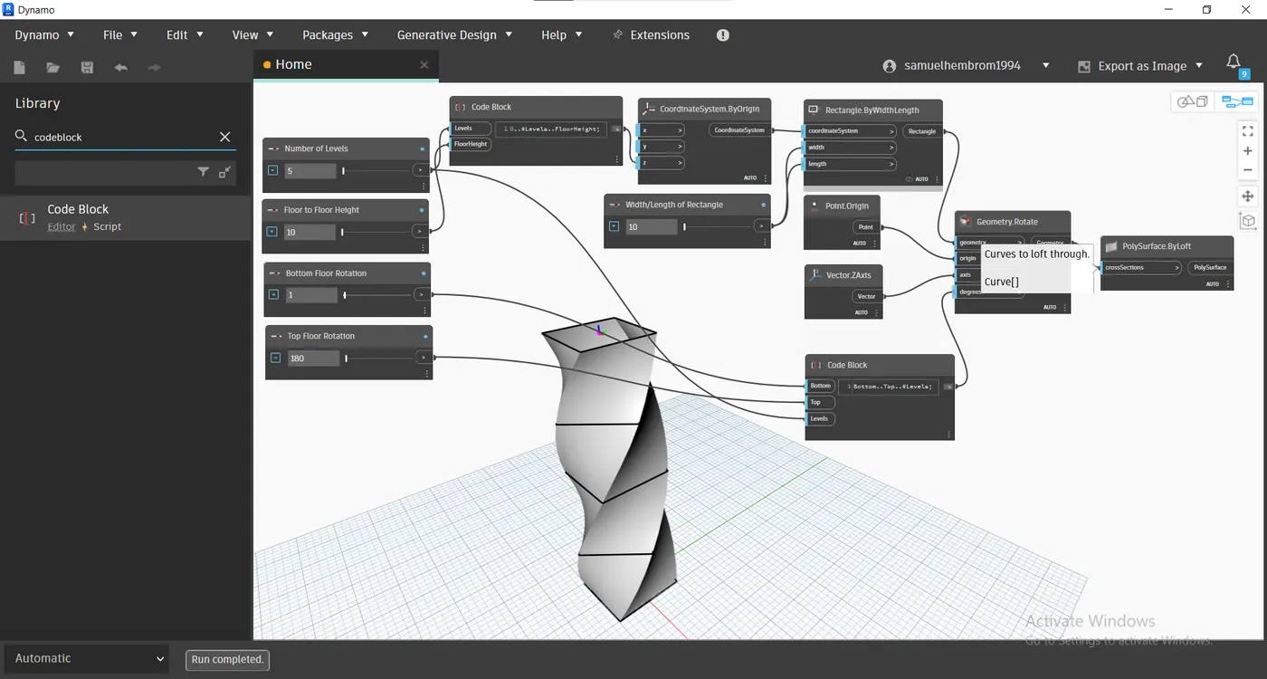
- Open four Integer Slider as shown in image below.
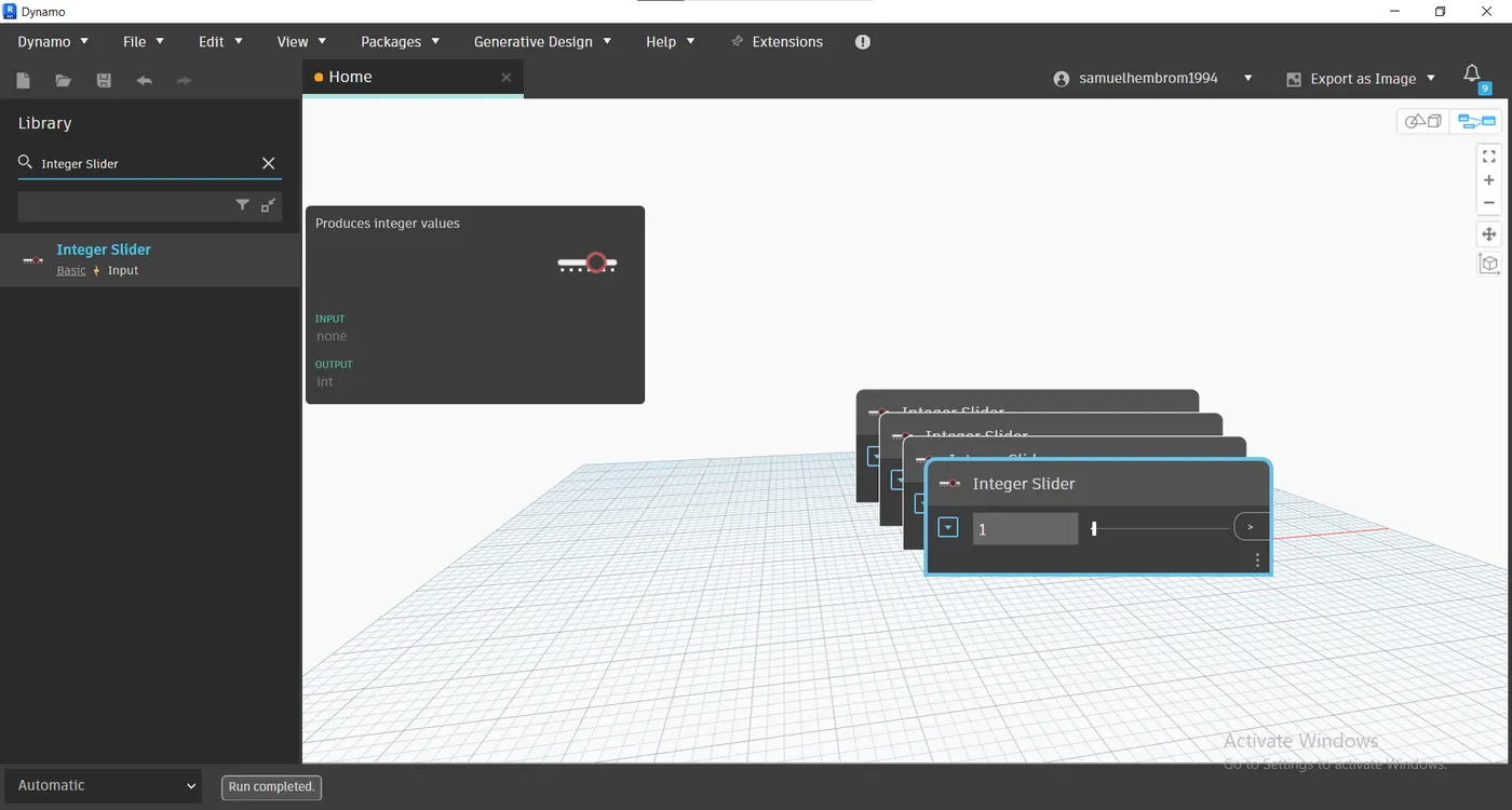
- Rename the integer slider as "Number of Levels", "Floor to Floor Height", "Bottom Floor Height" and "Top Floor Rotation".
- Set minimum and maximum values to 5 and 20 for "Number of Levels" block.
- Similarly set minimum and maximum values to 10 to 50 for "Floor to Floor Height" block.
- Again set minimum and maximum values to 0 to 180 for "Bottom Floor Rotation" block.
- Next set minimum and maximum values to 180 to 360 for "Top Floor Rotation" block.
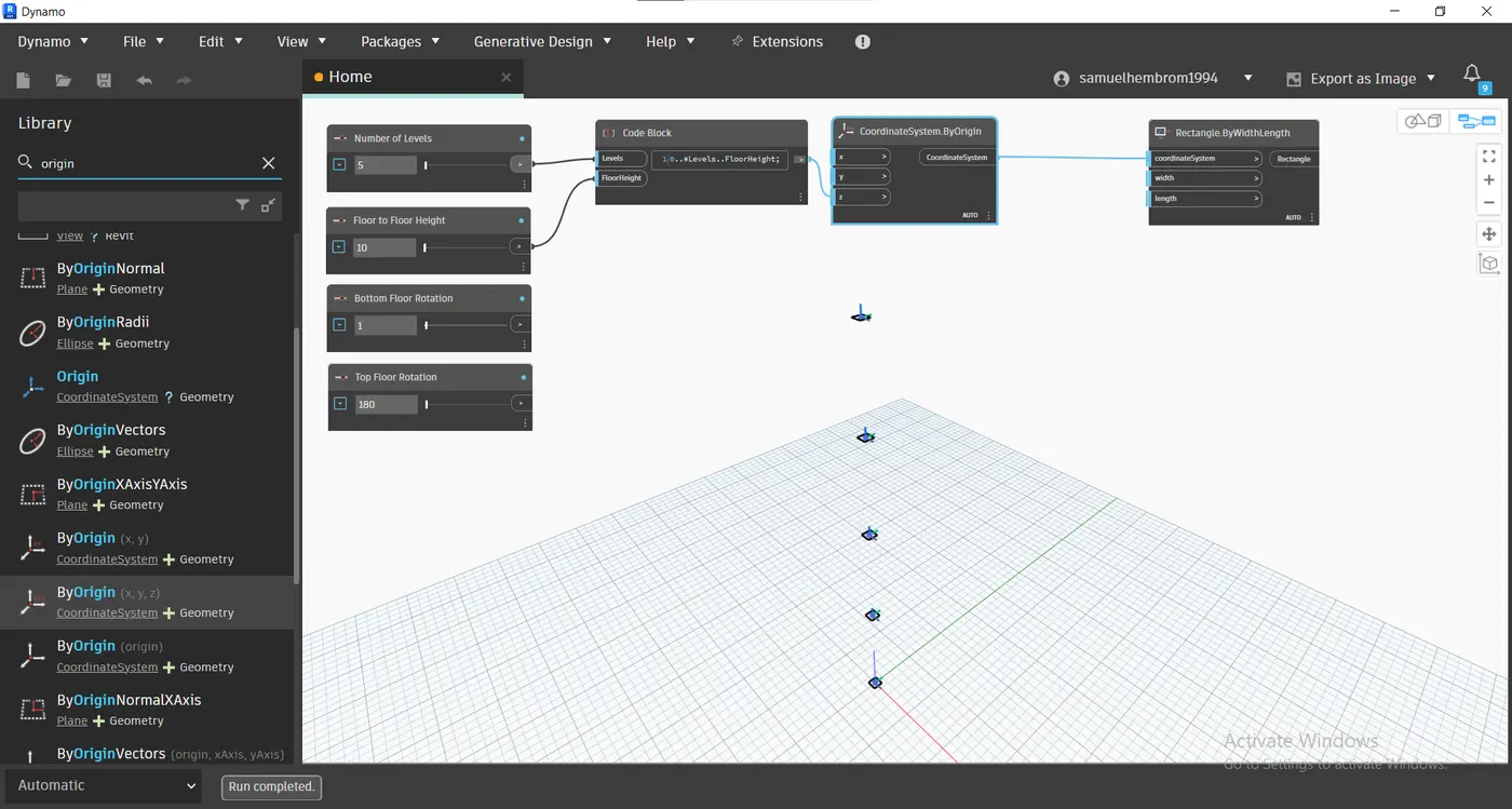
- Add point by coordinate from the library.
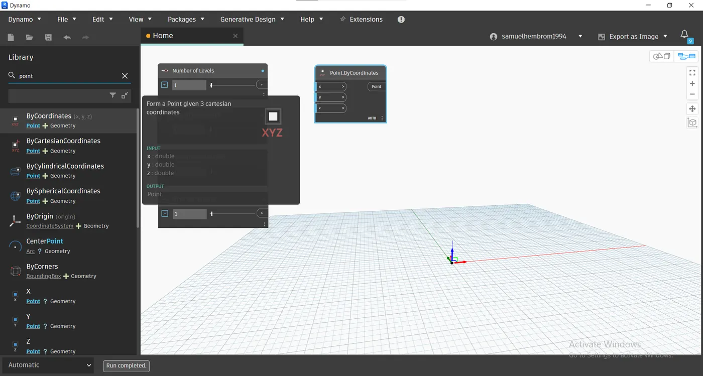
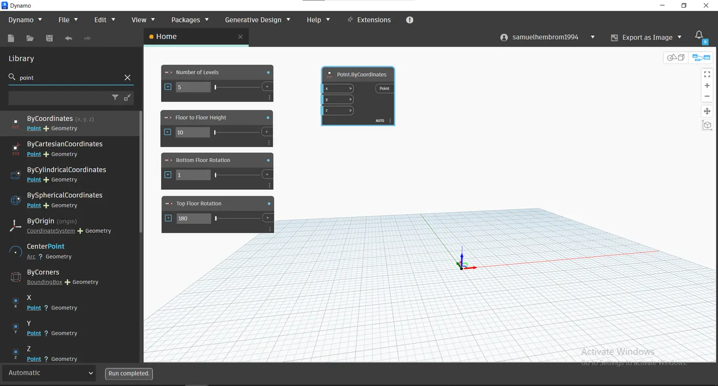
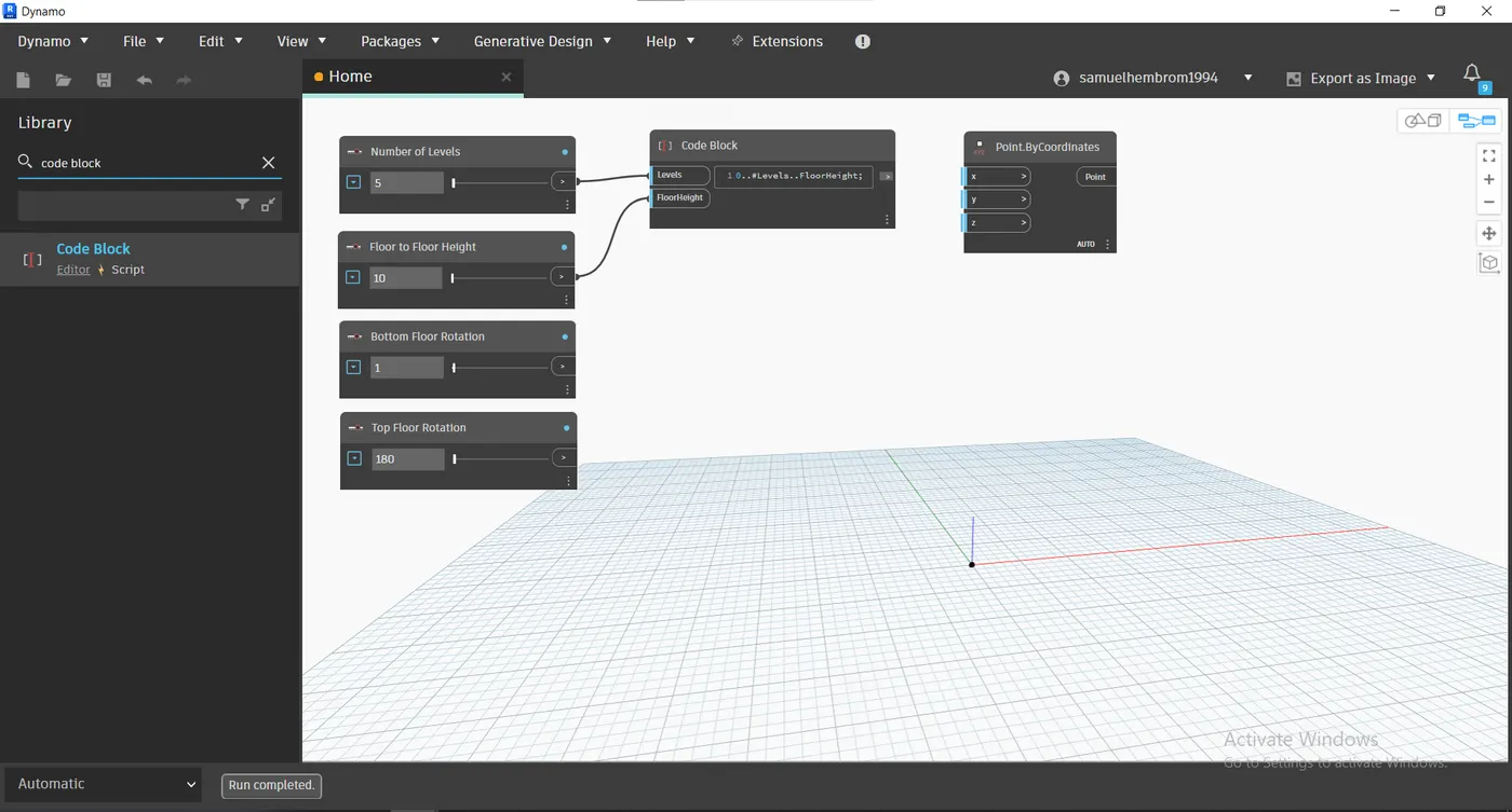
- Add a Code block from the library and provide the code "0..#Levels..FloorHeight;".
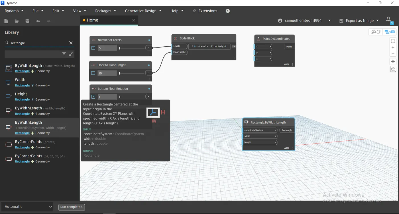
- In the search bar search for rectangle and in the library menu select "ByWidthLength".
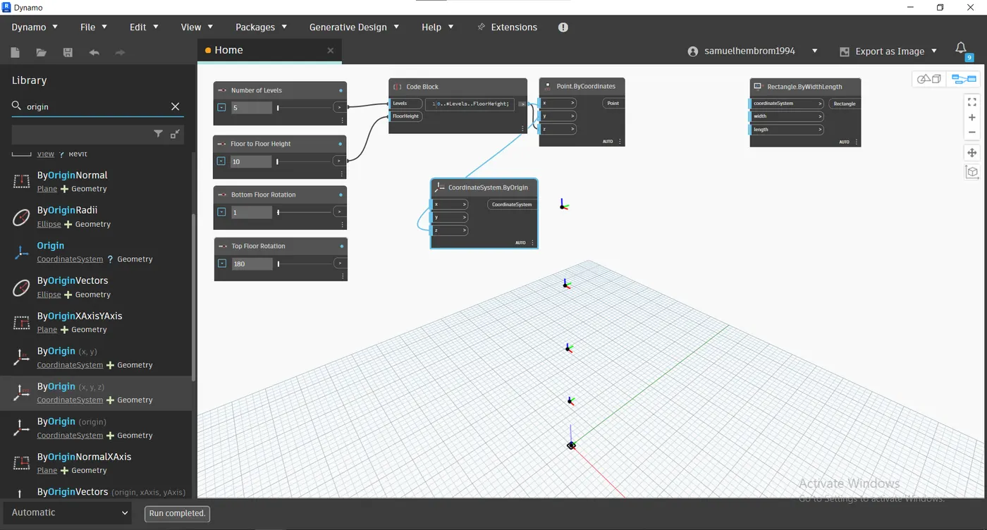
- Delete "Point.ByCoordinates" tab and join "CoordinateSystem.ByOrigin" block to "Rectangle. ByWidthLength" coordinate system option as shown in image below.
- And we will see that rectangles are made at control points.
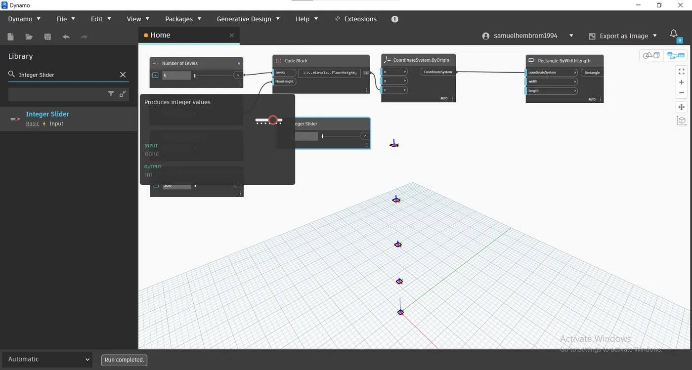
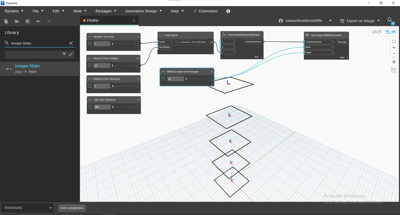
- Add an "Integer Slider" and rename it as "Width/Length of Rectangle".
- Set the minimum and maximum values to 10 to 20 respectively.
- Join the block to width and length option of "Rectangle.ByWidhtLength" block.
- We can see that rectangle's width has increased in below image.
- For creating surface out of the rectangle search for "polysurface" in the search bar and select "ByLoft" option.
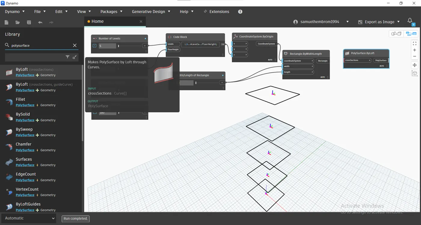
- Join the "Rectangle.ByWidthLength" block to "PolySurface.ByLoft".
- We can see that surface is made out of the rectangle.
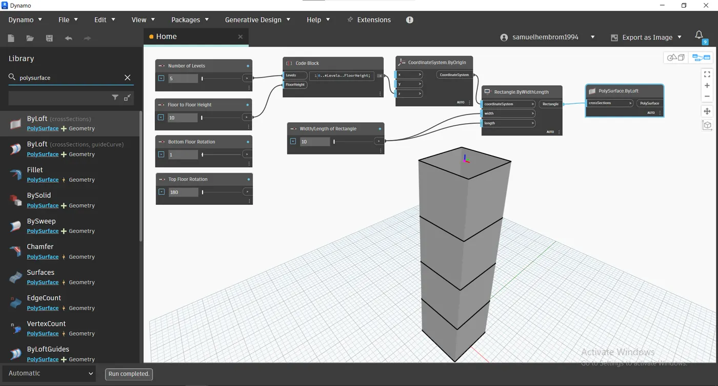
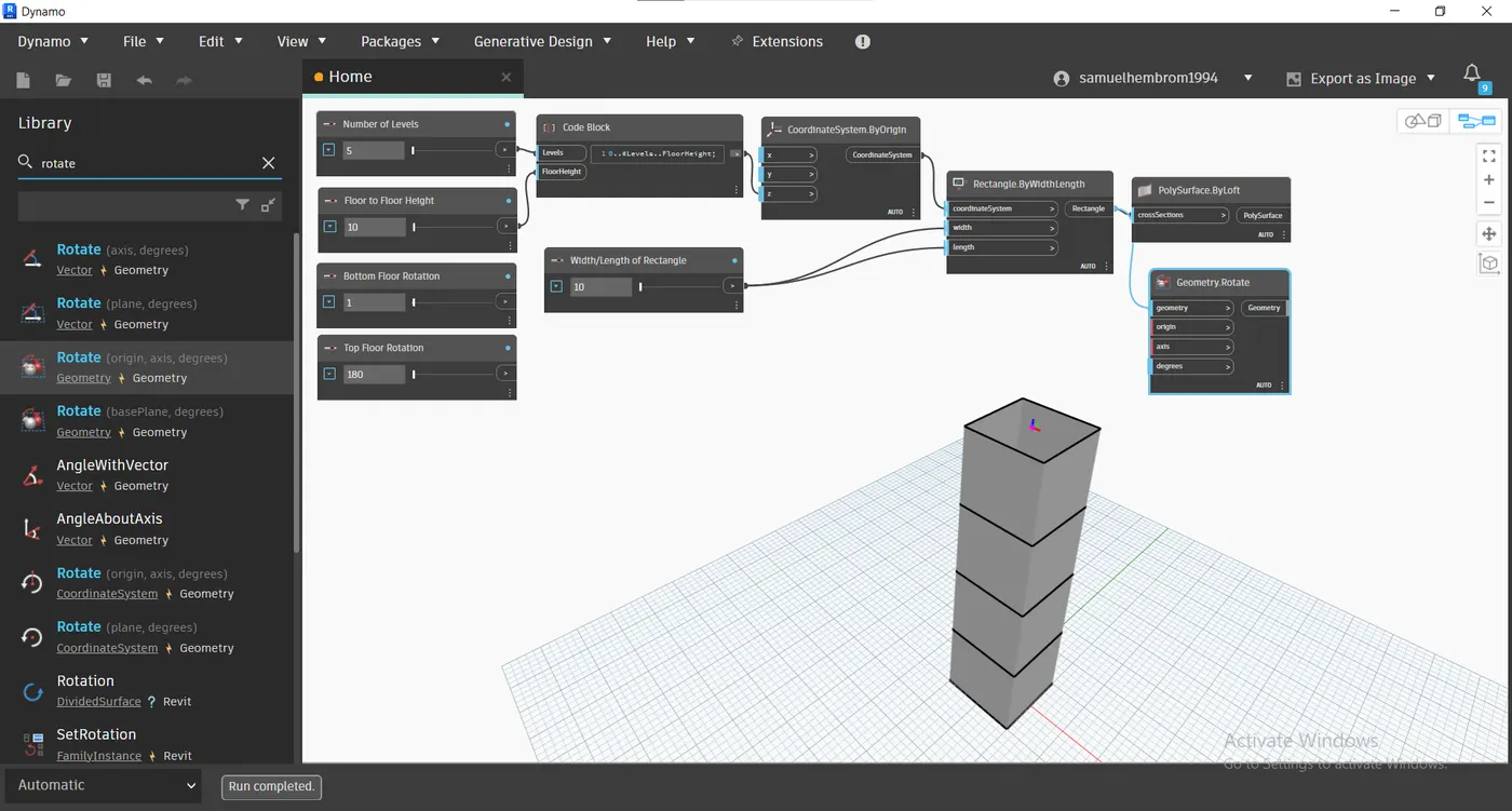
- Search for "Origin", "Zaxis" & "Code Block" and add them to model space.
- In the "Code Block" write the code as "Bottom..Top..#Levels;".
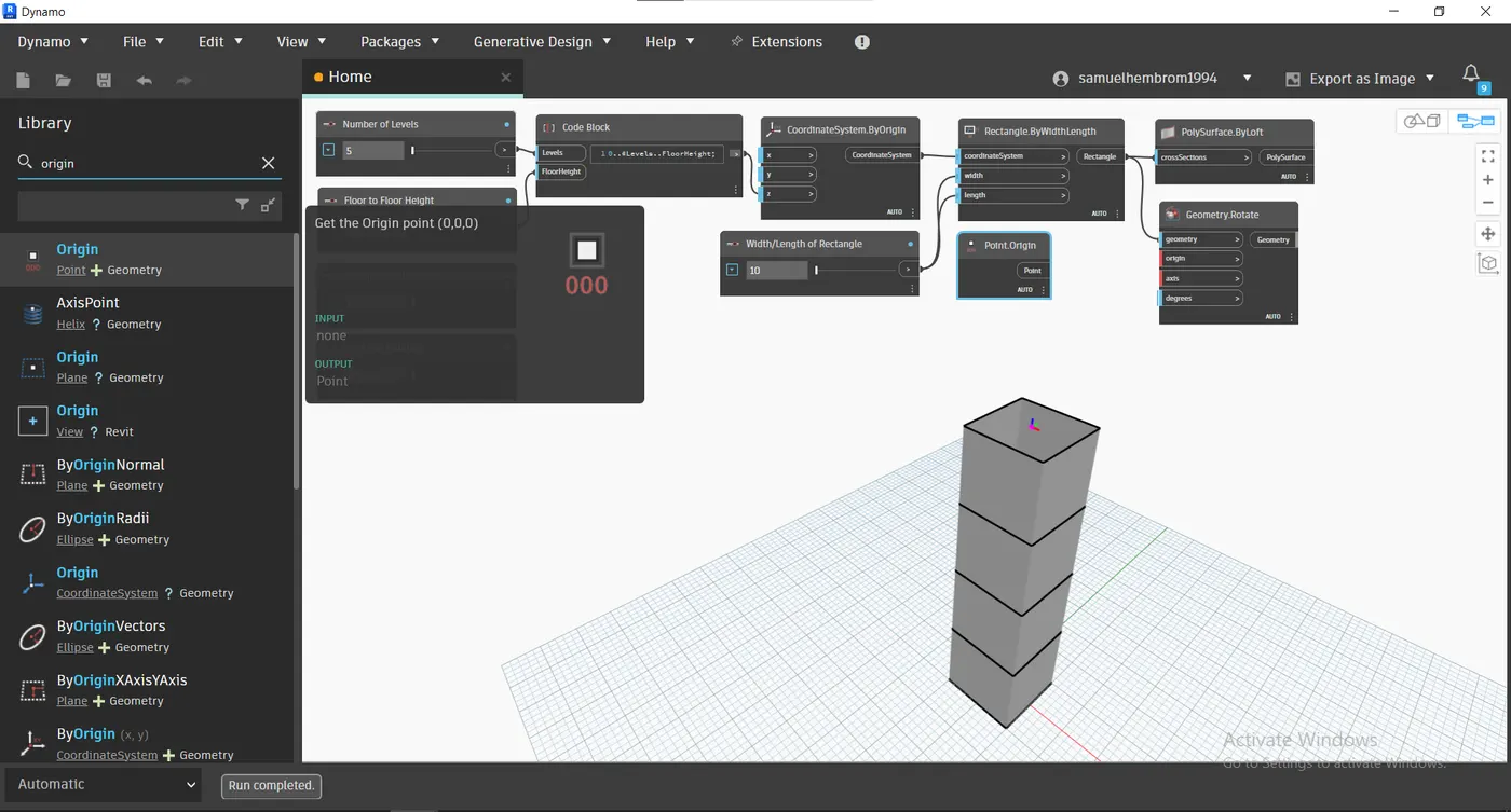
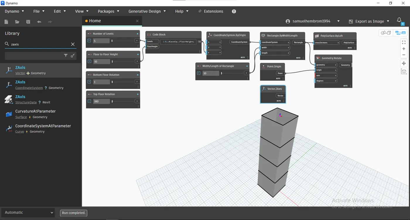
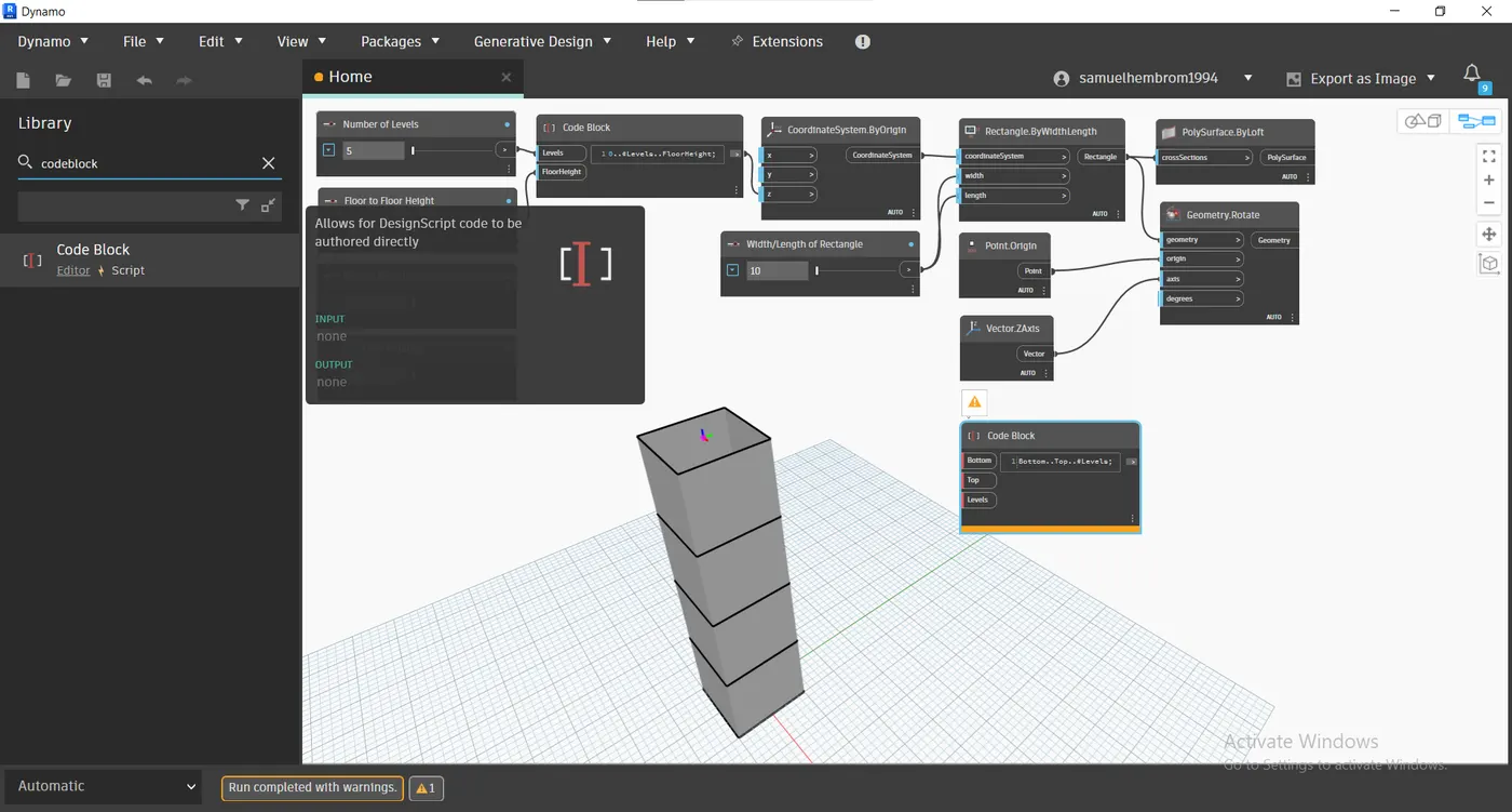
- Join the "Bottom Floor Rotation" and "Top Floor Rotation" to their respective option in "Code Block".
- Join the "Number of Levels" block to the respective option in "Code Block".
- Disconnect the "PolySurface.ByLoft" temporarily as shown in image below.
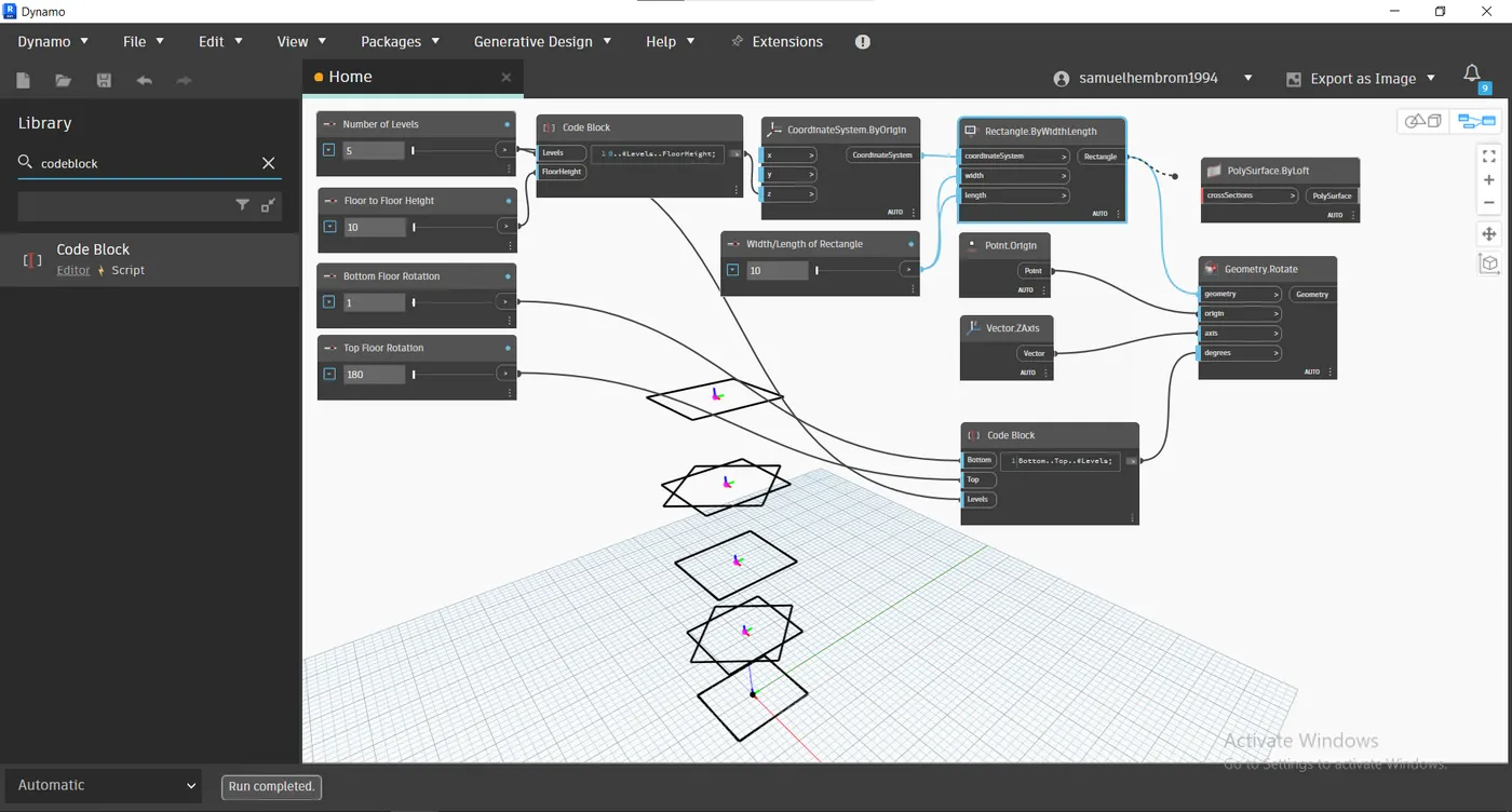
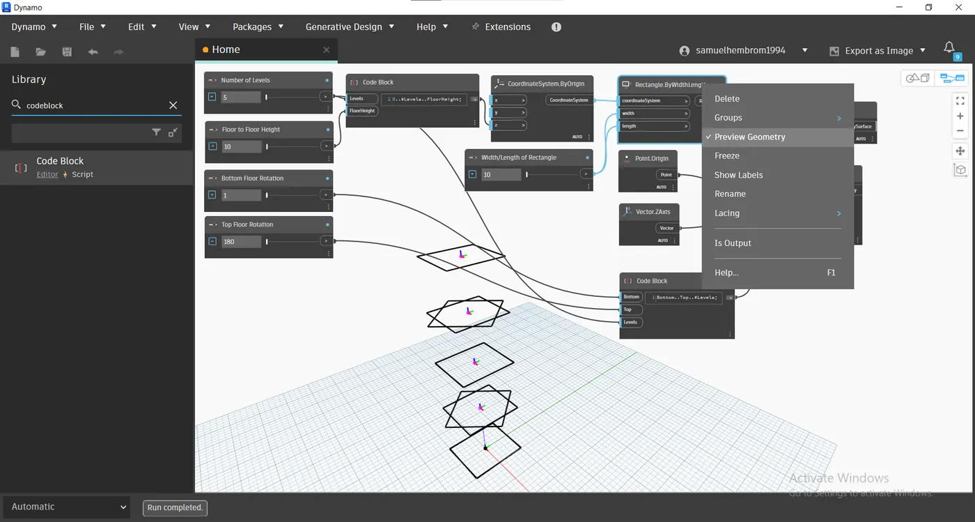
- For visualizing the rotated rectangles right click on the "Rectangle.ByWidthLength" and click on "Preview Geometry".
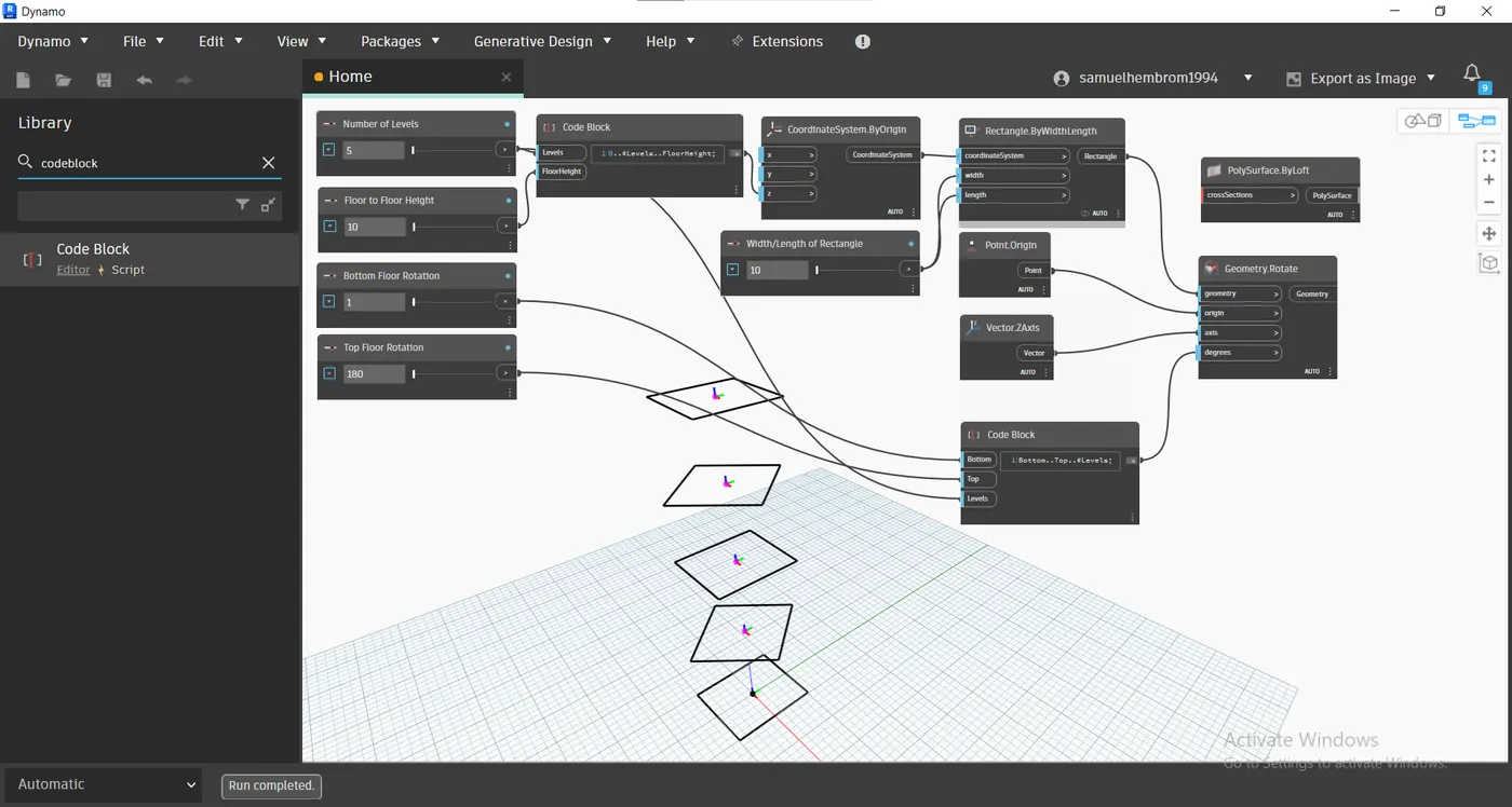
- Join the "Geometry.Rotate" block to "PolySurface.ByLoft" block as shown in image below.
Result:-
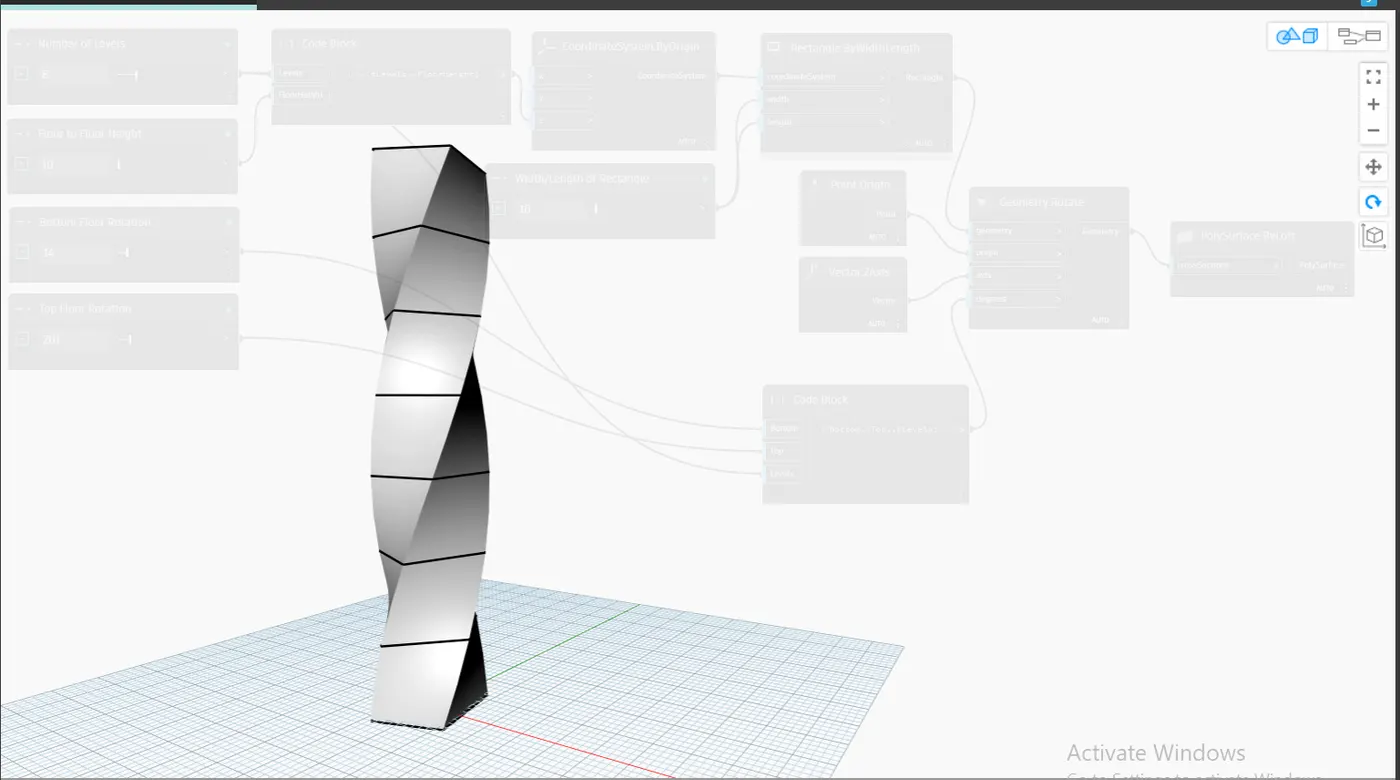
The parametric stadium have been created and is as given below.