Structural dynamics
1. Aim: Differentiate Static analysis and Dynamic analysis with proper representing pictures
Ans:
.The main difference between static and dynamic analysis is TIME! If the load is applied so slowly, that inertia effects won’t play a role, all you need is static analysis. Dynamic analysis handles impacts and other “fast” happening situations, but also vibrations (which happen in time).
.A static analysis can only be performed if the system being simulated does not depend on time, and if the loads being applied are constant. In a dynamic analysis, the system itself, the load application, or both might change with time.
.In a dynamic analysis, the inertial loads developed by the system due to acceleration are taken into account. Static analyses don’t consider inertia.
.Mathematically, the difference between static and dynamic analysis is that in a static analysis, only the stiffness matrix of the FEA model is solved. In a dynamic analysis, in addition to the stiffness matrix, the mass matrix (and damping matrix, if not zero) is solved as well. That is one of the reasons why dynamic analyses require more computational time than static analyses, for the same structure.
.In static analysis, we assume loads are applied very slowly, such slow that they are not even comparable with the natural vibration frequency of the structure. So it is as if the loads are static. And when the loads are static, we do not need to consider the effect of inertia and damping in the equation of motion but in dynamic analysis effect of inertia and damping force are to be considered in EOM.
2. Aim: Explain the following with relevant force-displacement graph
Ans:
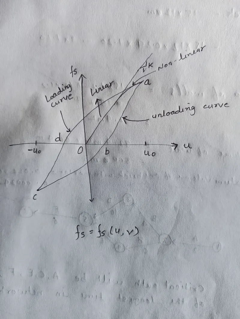
1. Elastic Behavior:-
Elastic behavior is the property of the material upto which the material can retain it's shape. From the aforementioned graph it is clearly mentioned that upto a certain point from "O" the graph is linear and shown its elastic properties.
2. Inelastic Behavior:-
Inelastic behavior is the property of the material when the material can't retain it's previous shape after a certain deformation. In the aforementioned graph inelastic behavior has been shown in the upper shape of the curve upto point "a".
3. Plastic Behavior:-
Plastic behavior occurs when the material completely lost it's ductility. In the aforementioned graph plastic behavior occurs during unloading after point "a".
4. Non-linear Inelastic Behavior:-
Non-linear inelastic behavior occurs after the line from "O" tends to bend towards point"a".
3. Aim: Explain Mass, Stiffness & Damping components in the equation of motion
Ans: Mass, Stiffness & Damping components in the equation of motion are as follows;
- The Single Degree of Freedom System as a combination of 3 pure independent systems such as the stiffness, the damping and the mass component.
The Stiffness Component – the frame without damping or mass. The external force fs on the stiffness component is related to displacement u by fs = ku, if the system is linearly elastic.
The Damping Component – the frame with its damping property with no stiffness or mass. The external force on the damping component is related to velocity by fd = ců, where fd is damping force, c is the viscous damping coefficient and ů is the velocity.
The Mass Component – the roof mass without the stiffness or damping of the frame. The external force fi on the mass component is related to the acceleration by fi = mű Then,
mű + fd + fs = p(t) --à mű + ců+ ku = p(t)
4. Aim: Provide relationship between Natural period (Tn) & Natural frequency (f) and provide their definitions
Ans:
Natural period (Tn) – is the vibration of the system (Tn) is the time required for the undamped system to complete one cycle of free vibration (Unit is in seconds). It is related to the natural circular frequency of vibration, ωn, in units of radians per second. With, Tn = 2π/ωn or ωn = 2π/Tn
Natural frequency (f) - number of cycle (or one complete revolution) executed by system in one second with units in hertz. Where, f=1/Tn
Natural vibration properties ωn, Tn and f depends only on mass and stiffness of the structure.
5. Aim: Explain in detail about Response spectrum & its Graph
Ans: Response spectrum;
.It’s the central concept in earthquake engineering, provides a convenient means to summarize the peak response of all possible linear SDF systems to a particular component of ground motion.
.It provides a practical approach to apply the knowledge of structural dynamics to the design structures and development of lateral force requirements in building codes.
.A plot of the peak value of a response quantity as a function of the natural vibration period Tn of the system, or a related parameter such as circular frequency ωn or cyclic frequency fn, is called the response spectrum for that quantity.
.Each such plot is for Single Degree of Freedom systems having a fixed damping ratio Շ, and several such plots for different values of Շ are included to cover the range of damping values encountered in actual structures.
.A variety of response spectra can be defines depending on the response quantity is plotted. Consider the following peak responses.
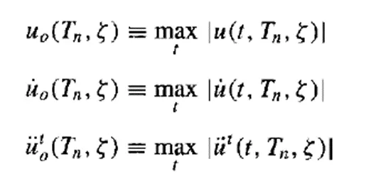
.The deformation response spectrum is a plot of uo against Tn for fixed Շ (damping ration). A similar plot for ůo is the relative velocity response spectrum, and for űto is the acceleration response spectrum.