Structural analysis of a buidling using Robot Structural Analysis
Question :- 1
What are HVAC systems? Why are they essential in the modeling of buildings.
Aim :-
- To Discuss about HVAC System.
Result :-
- The HVAC Full form is Heating, Ventilation, and Air Conditioning with respect to building structures.
- HVAC systems & types are important areas in the field of mechanical engineering.
- Basically, HVAC means the various systems and types used for moving air between different indoor and outdoor spaces.
- In addition to that, HVAC also offers heating and cooling in both residential and commercial buildings.
- HVAC systems ensure the air quality of a building.
- Specially-trained HVAC consultants are an important authority in the industry because HVAC & its types are an integral part of a building.
- No building is now complete without a proper HVAC system.
Essentiality :-
- HVAC systems play a crucial role in the maintenance of indoor air quality.
- Poor air quality was the largest factor for environment-related sickness. Efficient HVAC systems solve this problem.
- It circulates the air, regulates the temperature according to the weather, and removes harmful particles or gases from the air.
- It controls overall climate of the building.
- It enhances the air quality and productivity.
Question :- 2
From week 7 assignment, based on the building designed use the same Revit file to design a HVAC system for each floor to cover the topics included in the class.
a. Typical HVAC unit includes Distribution center
b. Collector
c. Ducts
d. Blower
Based on the layout choose appropriate ducts and elevation using property browser and assign the components to appropriate groups to complete modeling of the HVAC unit.
Aim :-
- To use the same Revit file to design a HVAC system for each floor to cover the topics included in the class.Based on the layout choose appropriate ducts and elevation using property browser and assign the components to appropriate groups to complete modeling of the HVAC unit.
Introduction :-
- HVAC systems & types are important areas in the field of mechanical engineering.
- Basically, HVAC means the various systems and types used for moving air between different indoor and outdoor spaces.
- In addition to that, HVAC also offers heating and cooling in both residential and commercial buildings.
- HVAC systems ensure the air quality of a building.
Procedure :-
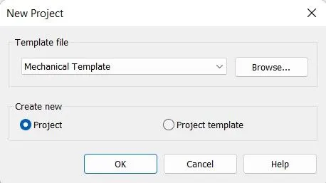
- Open Revit 2023.
- Click New from Models.
- So choose the tempalate file Mechanical Template.
- Cretae New Project.
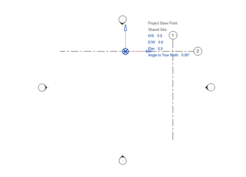
- Now draw the grids randomally in horizontal and vertical direction passing through eachother.
- Go to Manage TAb.
- Manage Tab -> Coordinates -> Specify coordinates at Points.
- Specify coordinates at Points where the intersection of the grids meets.
- Select Project base point.
- Save the Project.
- Re-open the Mechanical model.
- Go to Collaborate tab.
- New window will pop up named Collaborate.
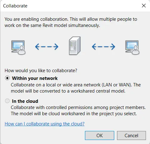
- In Collaborate window, Select the Within your Network Option.
- Click OK.
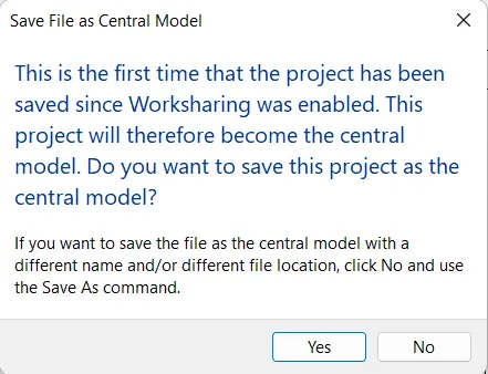
- Click File tab -> Save As (Project).
- New window will pop up named Save File As Central Model.
- Select the Mechanical Template.
- Go to Insert Tab. Select Lenk Revit.
- Select Architectural.
- Architectural Grids Drawing will be linked in the Structural Template, But not copied.
- To copy the Drawing, Click Collaborate tab -> Coordinate panel -> Copy/Monitor drop-down -> Select Link.
- Select the Architectural model in the drawing area.
- Click Copy/Monitor tab -> Tools panel -> Copy.
- To select multiple elements, on the Options Bar, select Multiple. Then select the elements in the drawing area, and click Finish on the Options Bar.
- Click Copy/Monitor tab -> Copy/Monitor panel -> Finish.
- So, Architectural template is copied in the Mechanical Templaet.
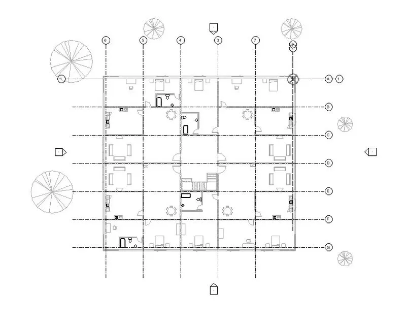
- HVAC systems are more used in different types of buildings such as industrial, commercial, residential and institutional buildings.
Collector :-
- A dust collector removes dirt, dust, debris, gases and chemicals from the air, providing your factory with cleaner air, which can provide numerous benefits.
- A central dust collector is designed to create a negative pressure at a dust source point and pull the fugitive material into the collector.
- Mechanical dust collector is defined as a device which separates dust in a dry state from gas through the application of in- ertial and gravitational forces only.
Duct :-
- Air ducts, or HVAC ductwork, or AC ducts, are conduits that supply warm or cool air to heat, ventilate, and cool each room.
- Air ducts are connected to the HVAC unit which filters then heats or cools your home’s air before sending it off.
- Air ducts are a vital part of your HVAC system, providing thermal well-being and good indoor air quality to your family.
Blower :-
- Air conditioner blower or fan is one of the key components that is needed as part of the air conditioning system.
- The function of the blower is to produce air movement to the space that is being conditioned.
- There are basically four types of fan that are commonly used in the HVAC equipment.
- They are the propeller fan, centrifugal fan, vane-axial fan and tube-axial fan.
- Add the Air Terminals and Blowers in the layout.
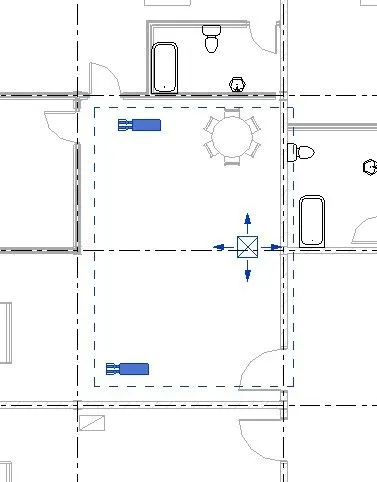
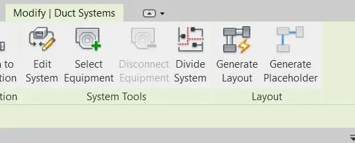
- Select the Generate Layout Option.
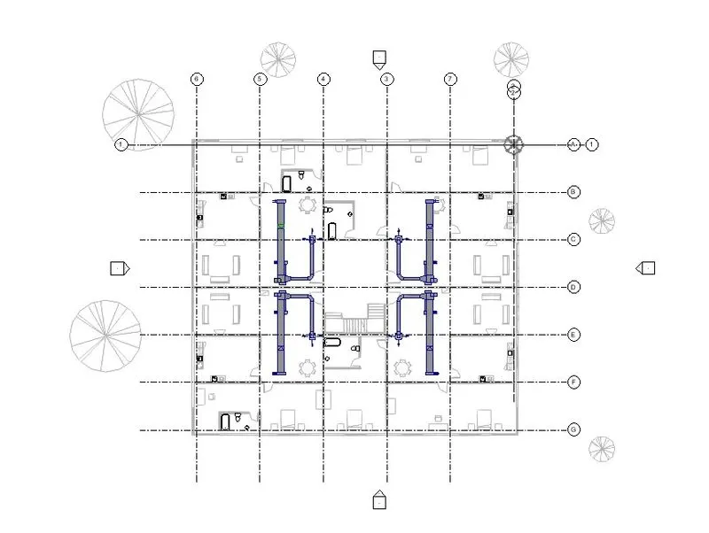
- MEchanical Equipments are added in the model.
Question :- 3
Use the add-ins tab to load plug-ins for robot structural analysis to your Revit software.
Result :-
- Open Revit 2023.
- We can see shoping cart symbol on the top right side.
- Click on it.
- Type structural Analysis Toolkit 2023 in searchbox.
- Choose Download.
- Install the file.
- Or we can get the product from the official website.
Question :- 4
Why do we need to assess buildings/analyze while modeling elements? Does design affect modeling in anyways?
Result :-
- Analyze The Analyze tab contains the tools necessary to modify energy analysis settings and to run an energy simulation via Green Building Studio.
- A representation of the structural physical model consisting of analytical elements, geometry, material properties, and loads.
- It is created automatically while creating the physical model. You export the analytical model to the structural analysis and design software.
- Apply structural loads to your analytical model to assess possible deformations and stress in your design.
- The Revit model is a virtual version of the building design.
- The model describes not only the geometry of the model elements, but also captures the design intent and logical relationships between the elements in the model.
- Creates a 3D virtual representation of the design. The views of the project are slices of the model at a particular position. Every view of the model is a live view of the elements.
- Shows the model from a specific viewpoint, such as a floor plan or section of the model.
- All views are live and changes to an element in one view will be instantly propagated to the other views of the model, keeping all views in sync.
- Establishes relationships between elements, so when an element is altered, the elements it is constrained to will also be changed to maintain the design intent of the model.
- It helps to calculate the load and internal forces.
- It helps to cross check th engineering design.
- It can analyze each and every element.
Question :- 5
From the structural model developed in week 6 and 7, export the complete analytical model to robot structural analysis.
a. List your assumptions on what boundary conditions will be realistic for the analysis approach
b. Use the design standards to decide what loads must be applied to floorings based on the type of structure decided
c. List the load combinations and include them in the analysis model
d. Analyze the building and report the following results
i. Maximum Moment in each floor for all Load Combinations
ii. Maximum Displacement in each floor for all Load combinations
iii. Lateral Displacement in building for all Lateral Load combinations
e. After analysis, do you think you have a better approach or idea in modeling structural members?
Aim :-
- To export the complete analytical model to robot structural analysis.
A.
- A place where either external force or displacement are known at the begining of analysis is boundary condition.
- To solve the problem of structural analysis, location on the boundary of structure must hav eknown force.
- The known force must have some magnitude or it can be zero.
B.
- Loads that must be supplied to floorings are dead load, live load, wind load and Load combination of all 3 loads.
C.
Load Calculations :-
1.25 DL + 1.5 LL + 1 WL
D.
- From the structural model developed in week 6 and 7, export the complete analytical model to robot structural analysis.
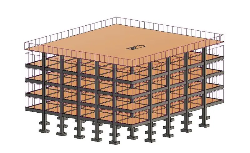
- We are using the same structural model that are used in the second project.
- We have applied the loads on the every floor.
- We have applied the area load.
- Now open the analytical model of applied loaded structure by Analytical Automation.
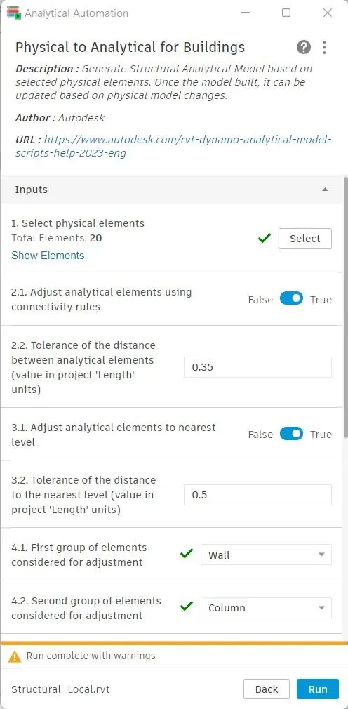
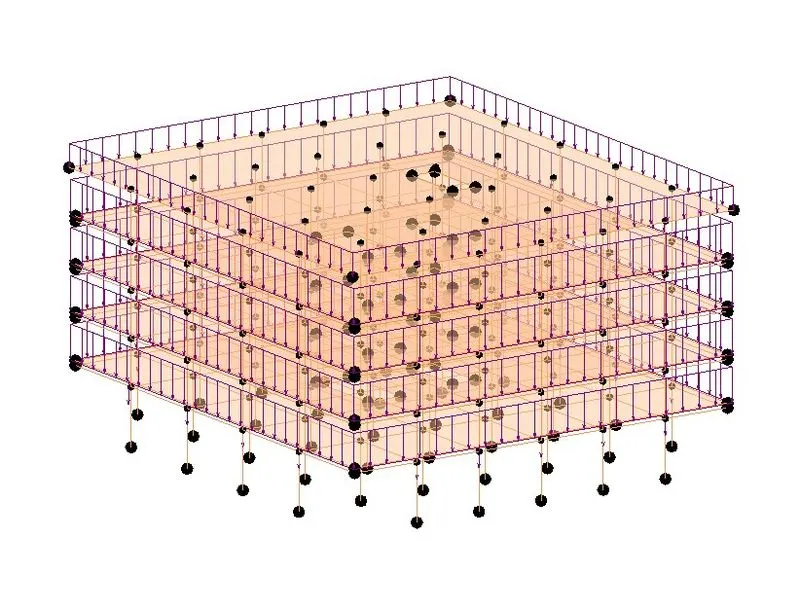
- Analytical model is opened.
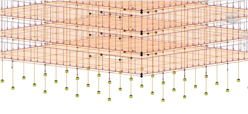
- Now add the boundary conditions in the foundation level of building.
- Now slect the option named load cases.
- Add the Loads that you want to apply in your model.
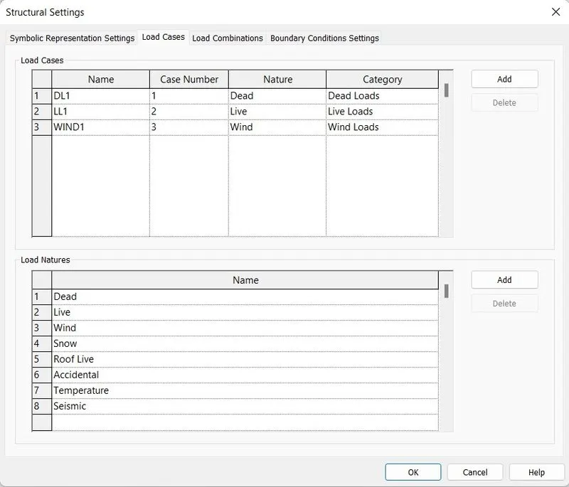
- Now add the load combinations from analyze tab.
- Add the combinations by selecting Edit Selected Formula.
- Add the factor of load.
- And make the load combination.
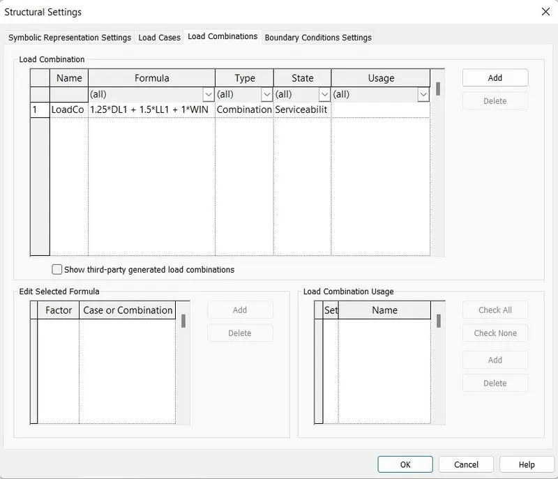
- Load and Load combinations are applied in the model.
- Now export the model to Robot Structural Analysis.
- Go to Analyze tab.
- Select Robot Structural Analysis.
- Now select Robot Structural Analysis link.

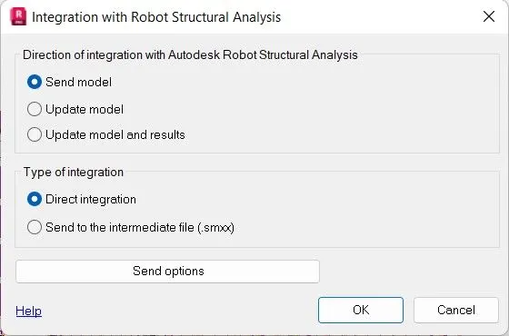
- Now it will Automatically export the model to Robot Structural Analysis.
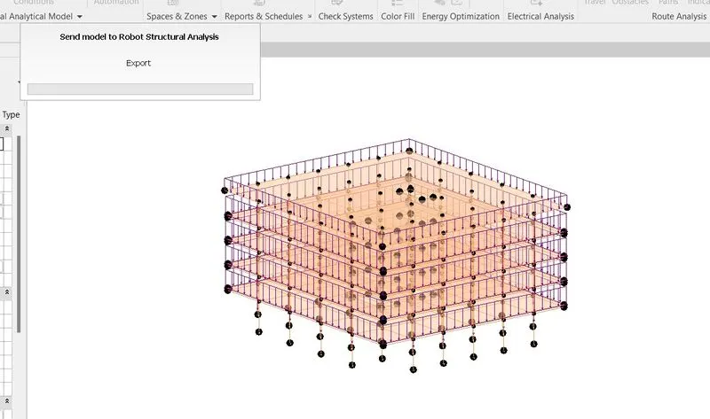
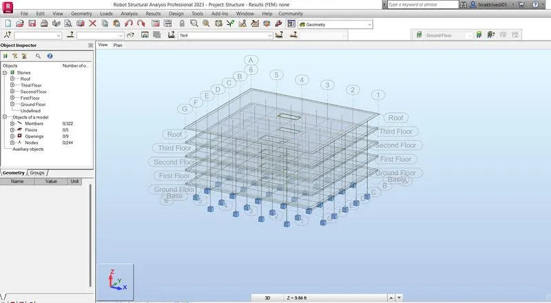
- Robot Structural Analysis will open.
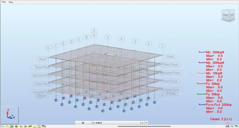
- Below image is showing the workplace of Robot Structural Analysis.
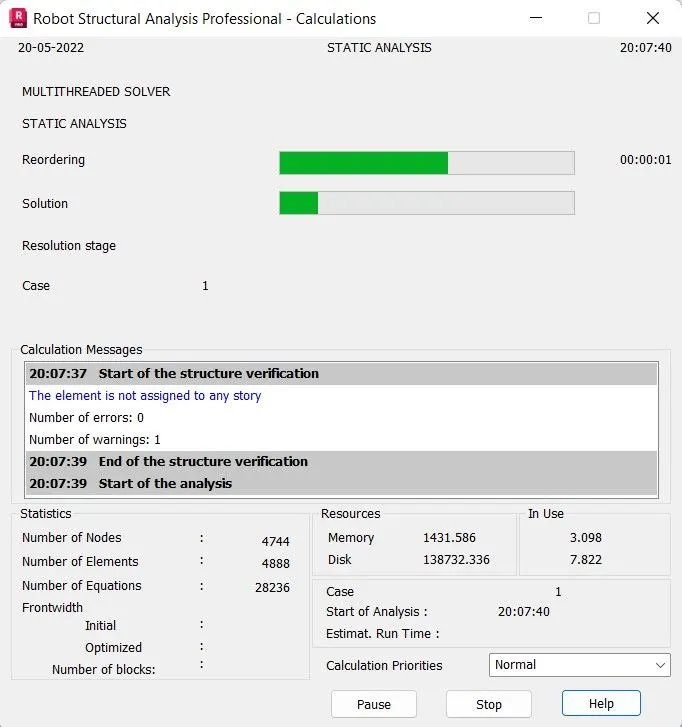
- Click Analysis -> Calculations.
- The calculation process starts. The Calculations dialog shows the advancement of the process, which depends on the size of the project being analyzed.
- Once the calculations are complete the information: Results (FEM): available is displayed at the top and the bottom of the program.
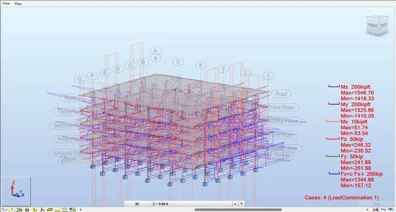
- In the Cases Selection box of the Selection toolbar, expand the Cases drop-down menu and select 5: COMB1.
- Now go to Result tab.
- Select diagram in place.
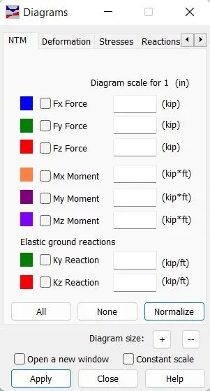
- Select apply.
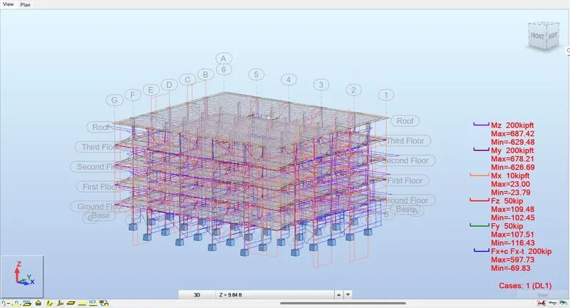
- Analyze the loads acting on the model
- Also analyze moment applied on the model.
Result :-
- Loads and loads combinations are applied on the model.
Question :- 6
What is energy analysis and why do we need to consider it while modeling in Revit? How does the factor of sustainability improve the quality of your design?
Result :-
- Perform energy analysis on the building design through all stages, from the earliest conceptual phase through detailed design, to ensure that you are constantly working towards the most energy efficient building possible.
- Energy simulation can help you analyze the movement of energy in, out, and through the rooms and volumes in a building model.
- This information can help designers make better informed, cost-effective decisions that improve the performance and reduce the environmental impact of buildings.
- Whole building energy simulation measures expected energy use (fuel and electricity) based on the building's geometry, climate, building type, envelope properties, and active systems (HVAC & Lighting).
- Use Energy Analysis for Autodesk Revit to perform energy simulation for conceptual forms and detailed architectural models created in Revit.
- Use the simulation results to understand building energy use. Then iterate the designs to improve their sustainability ratings.
- In later stages of the design process, you can use a Revit model consisting of building elements to perform an energy analysis.
- During the design process, you can perform energy analysis using a combination of Revit conceptual masses and building elements.
- When preparing a Revit model for energy analysis, you can define thermal properties for the materials and elements included in the simulation.
- Designing and delivering more sustainable projects can be complex.
- It requires close coordination across different project stages, from design through construction and operation.
- Many firms are looking for the best way to integrate building information modeling (BIM) technology with sustainable design and analysis tools.
- BIM is core to Autodesk’s sustainable design approach for building performance analysis and simulation.