Creating a Floor plan, Footing detail and Isometric view using AutoCad
Aim :-
To creating the floor plan, flooring detail and isometric view using Autocad.
Introduction :-
The main objective of this assignment is to get in touch with various tools in AUTOCAD like the rectangle, polylines, modifications tools . These tools will be understood by creating a flooring detail, two bedroom building, cross sections of a 2 bedroom building showing foundation detail and isometric view of steps and gable view.
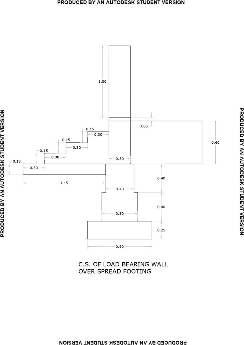
Drawing-1 :- C/S of Load Bearing wall over spread Footing
Procedure :-
- The Step by step procedure of drawing is as per following.
A.
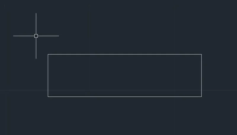
- Type REC in command line and press enter.
- Specify first corner of rectangle.
- Enter D for Dimension.
- Enter Length : 0.90
- Enter Width : 0.25
- Specify other Corner.
B.
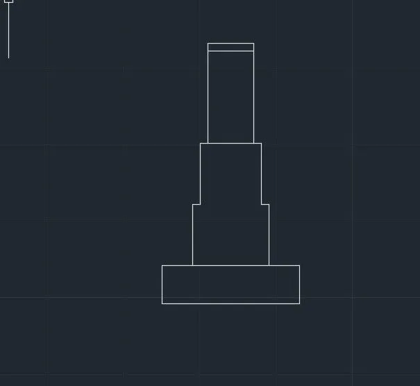
- Type L in command line and press enter.
- Specify Start Point A.
- Specify Next Point @0.20,0
- Specify Next Point @0,0.40
- Specify Next Point @0.05,0
- Specify Next Point @0,0.40
- Specify Next Point @0.05,0
- Specify Next Point @0,0.60
- Specify Next Point @0.30,0
- Specify Next Point @0,-0.60
- Specify Next Point @0.05,0
- Specify Next Point @0,-0.40
- Specify Next Point @0.05,0
- Specify Next Point @0,-0.40
C.
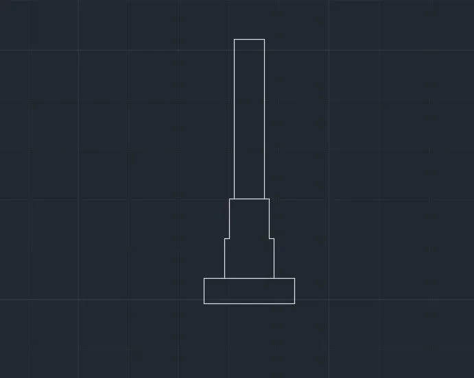
- Type L in command line and press enter.
- Specify Start Point B.
- Specify Next Point @0,0.05
- Specify Next Point @0.30,0
- Specify Next Point @0,-0.05
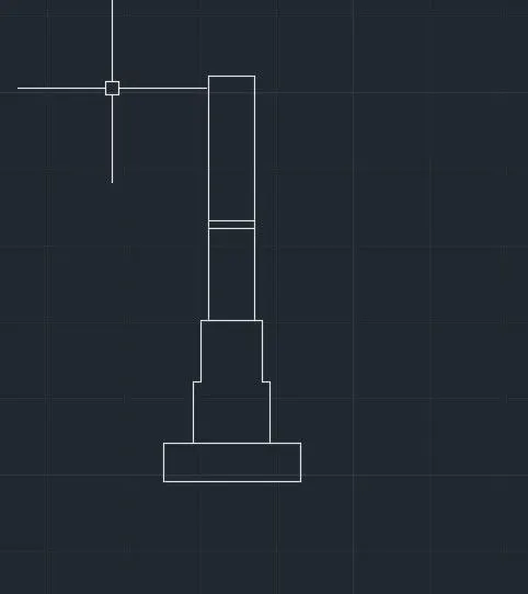
D.
- Type L in command line and press enter.
- Specify Start Point C.
- Specify Next Point @0,1
- Specify Next Point @0.30,0
- Specify Next Point @0,-1
E.
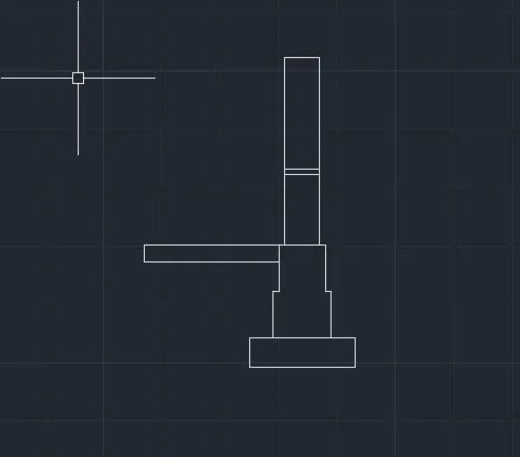
- Type L in command line and press enter.
- Specify Start Point D.
- Specify Next Point @-0.30,0
- Specify Next Point @-0.05,0
- Specify Next Point @-1.15,0
- Specify Next Point @0,-0.15
- Specify Next Point @1.15,0
F.
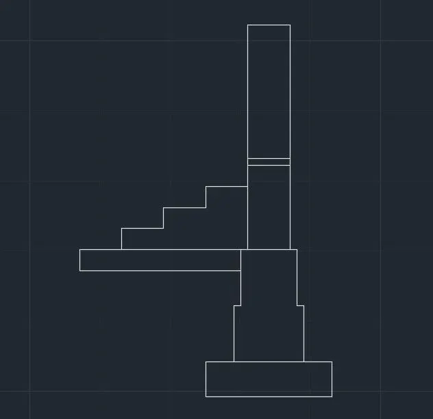
- Type L in command line and press enter.
- Specify Start Point E.
- Specify Next Point @0.30,0
- Specify Next Point @0,0.15
- Specify Next Point @0.30,0
- Specify Next Point @0,0.15
- Specify Next Point @0.30,0
- Specify Next Point @0,0.15
- Specify Next Point @0.30,0
G.
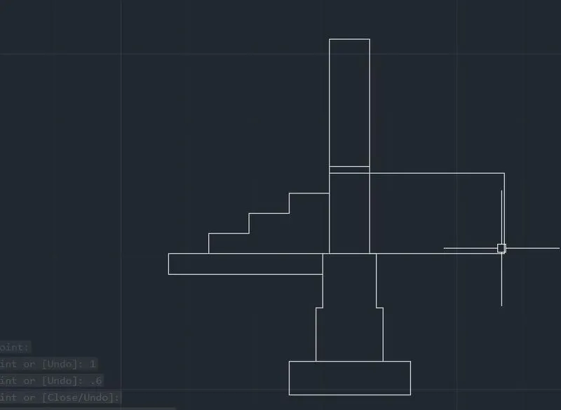
- Type L in command line and press enter.
- Specify Start Point F.
- Specify Next Point @1,0
- Specify Next Point @0,-0.60
- Specify Next Point @-0.95,0
H.
- Give the dimensions as per drawing using dimension command for command bar.
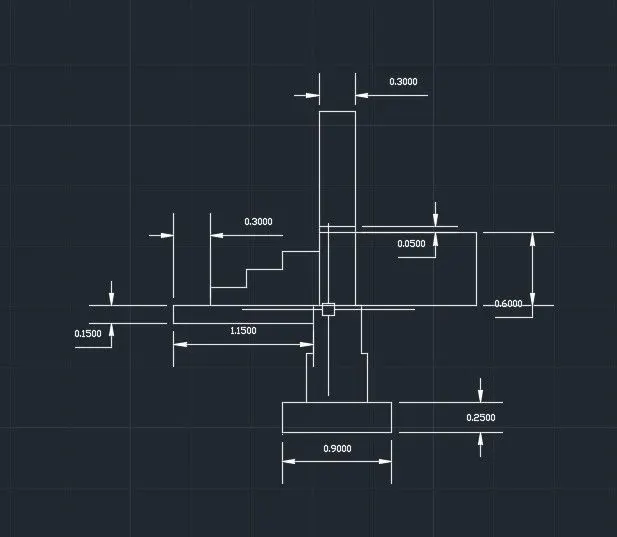
- C/S of Load Bearing wall over spread Footing is Completed.
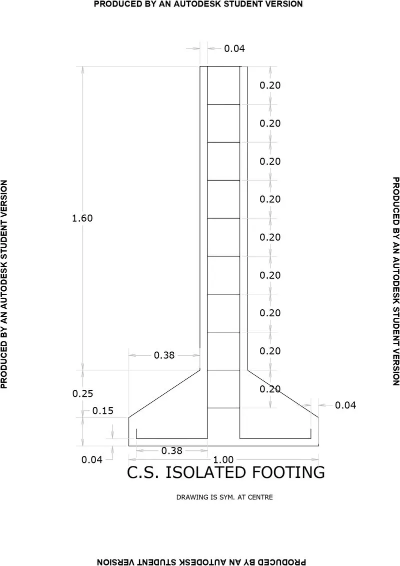
Drawing-2 :- C/S of Isolated footing
Procedure :-
- The Step by step procedure of drawing is as per following.
A.
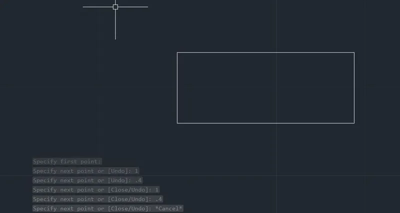
- Type REC in command line and press enter.
- Specify first corner of rectangle.
- Enter D for Dimension.
- Enter Length : 1
- Enter Width : 0.40
- Specify other Corner.
B.
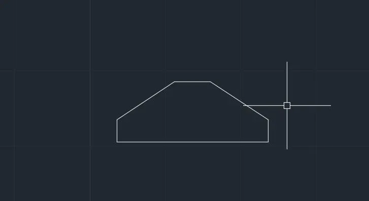
- Type CHA in command line and press enter.
- Enter D for Dimension.
- Specify First Chamfer distance : 0.25
- Specify Second Chamfer distance : 0.38
- Select first line ab and second line as bc.
- Repeat the process for line cd and bc.
C.
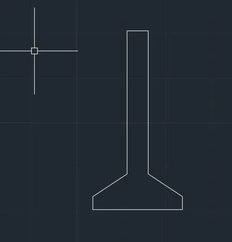
- Type L in command line and press enter.
- Specify Start Point E.
- Specify Next Point @0,1.60
- Specify Next Point @0.24,0
- Specify Next Point @0,-1.60
D.
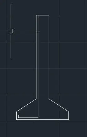
- Type L in command line and press enter.
- Specify Start Point G.
- Specify Next Point @0.04,0.
- Specify Next Point @0,-1.96
- Specify Next Point @-0.38,0
- Specify Next Point @0,0.04
E.
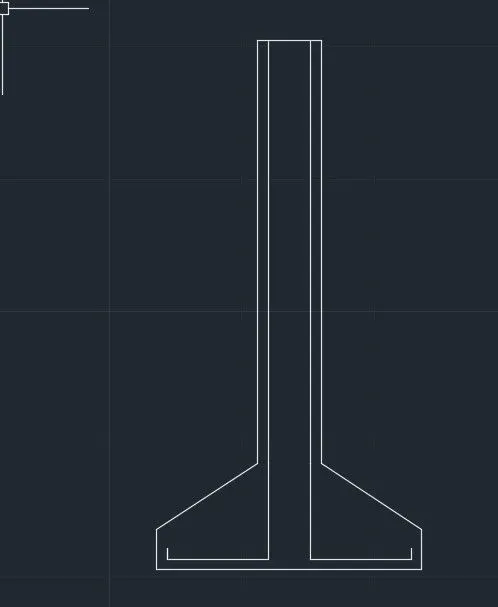
- Type L in command line and press enter.
- Specify Start Point H.
- Specify Next Point @-0.04,0.
- Specify Next Point @0,-1.96
- Specify Next Point @-0.38,0
- Specify Next Point @0,0.04
F.
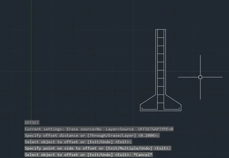
- Type L in command line and press enter.
- Specify Start Point I.
- Specify Next Point : @0.12,0
- Type O for OFFSET in command line and press enter.
- Specify offset distance : 0.20
- Select the object to offset ij.
- Move the Cursor inside to place the line and continue till required.
G.
- Give the dimensions as per drawing using dimension command for command bar.
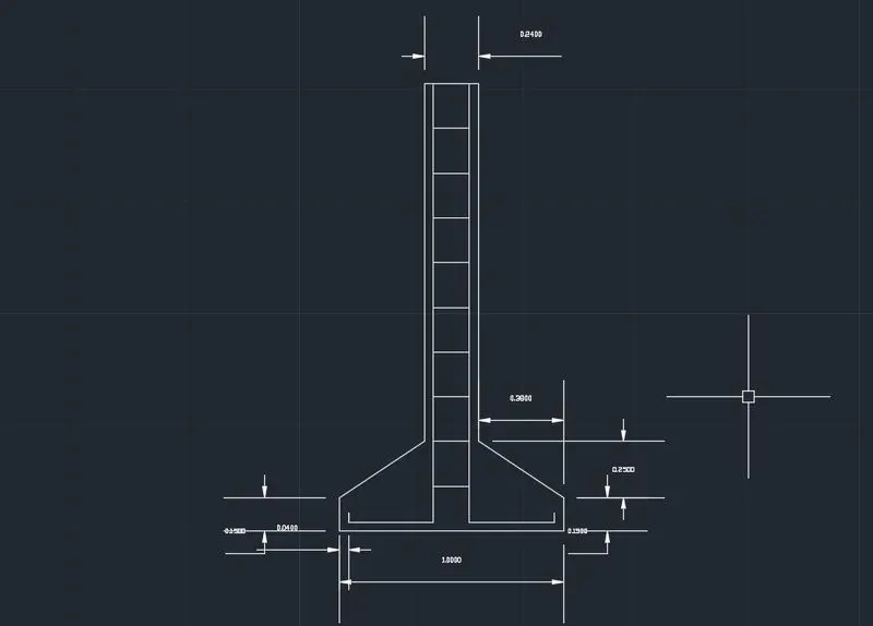
- C/S of Isolated footing is Completed.
Drawing-3 :- Line Diagram of Two Bedroom Building :-
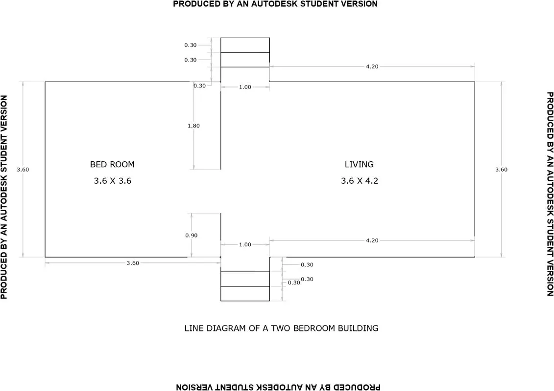
Procedure :-
- The Step by step procedure of drawing is as per following.
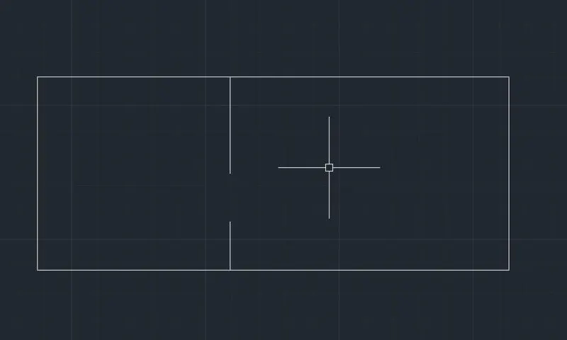
A.
- Type L in command line and press enter.
- Specify Start Point A.
- Specify Next Point @0,1.80
- Specify Next Point @-3.60,0
- Specify Next Point @0,-3.60
- Specify Next Point @3.60,0
- Specify Next Point @1,0
- Specify Next Point @4.20,0
- Specify Next Point @0,3.60
- Specify Next Point @-4.20,0
- Specify Next Point @-1,0
B.
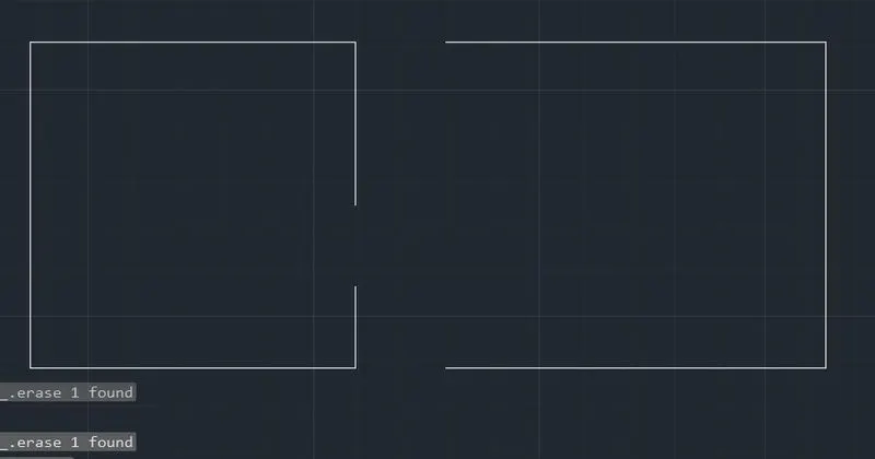
- Delete Line bc and de.
C.
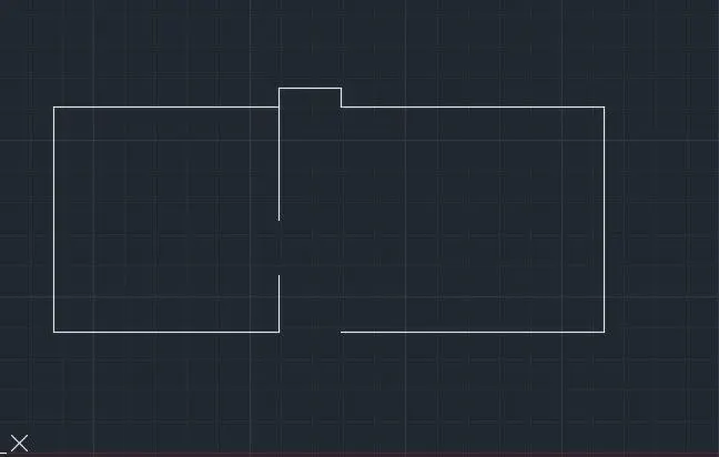
- Type PL in command line and press enter.
- Specify the first point of Polyline b.
- Specify Next Point @0,0.30
- Specify Next Point @1,0
- Specify Next Point @0,-0.30
D.
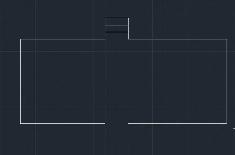
- Type CO in command line and press enter.
- Select the above polyline and specify the base point and paste it as required.
E.
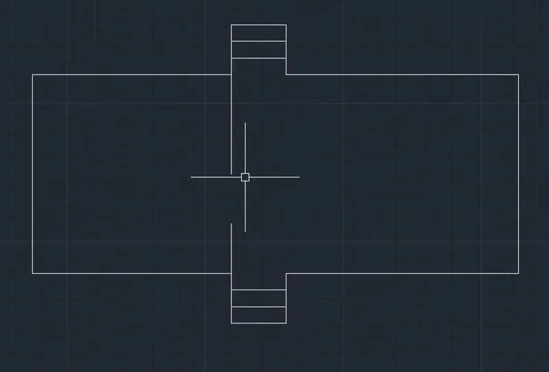
- The above two steps is to be followed here also in the same manner.
F.
- Give the dimensions as per drawing using dimension command for command bar.
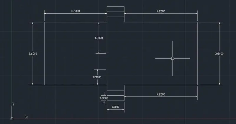
- Line Diagram of Two Bedroom Building is Completed.
Drawing-4 :- C/S of Load Bearing wall Showing Foundation details :-
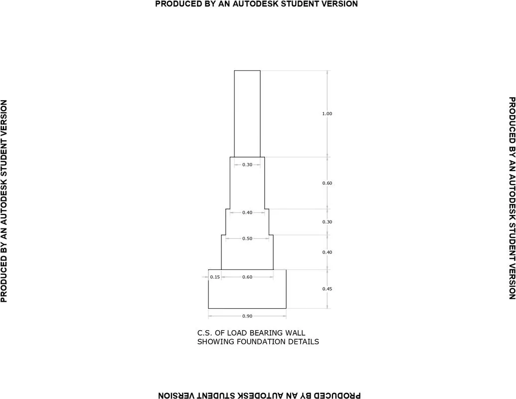
Procedure :-
- The Step by step procedure of drawing is as per following.
A.
- Type L in command line and press enter.
- Specify Start Point A.
- Specify Next Point @0,0.45
- Specify Next Point @0.15,0
- Specify Next Point @0,0.40
- Specify Next Point @0.05,0
- Specify Next Point @0,0.30
- Specify Next Point @0.05,0
- Specify Next Point @0,0.60
- Specify Next Point @0.05,0
- Specify Next Point @0,1
- Specify Next Point @0.30,0
- Specify Next Point @0,-1
- Specify Next Point @0.05,0
- Specify Next Point @0,-0.60
- Specify Next Point @0.05,0
- Specify Next Point @0,-0.30
- Specify Next Point @0.05,0
- Specify Next Point @0,-0.30
- Specify Next Point @0.05,0
- Specify Next Point @0,-0.40
- Specify Next Point @0.15,0
- Specify Next Point @0,-0.45
- C.
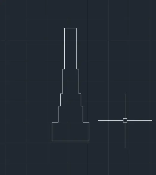
B.
- Give the dimensions as per drawing using dimension command for command bar.
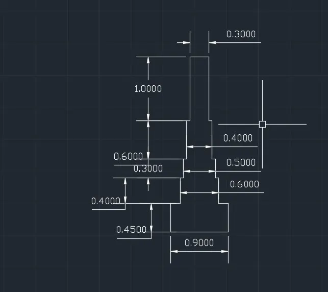
- C/S of Load Bearing wall Showing foundation details is Completed.
Drawing-5 :- Isometric views of Steps :-
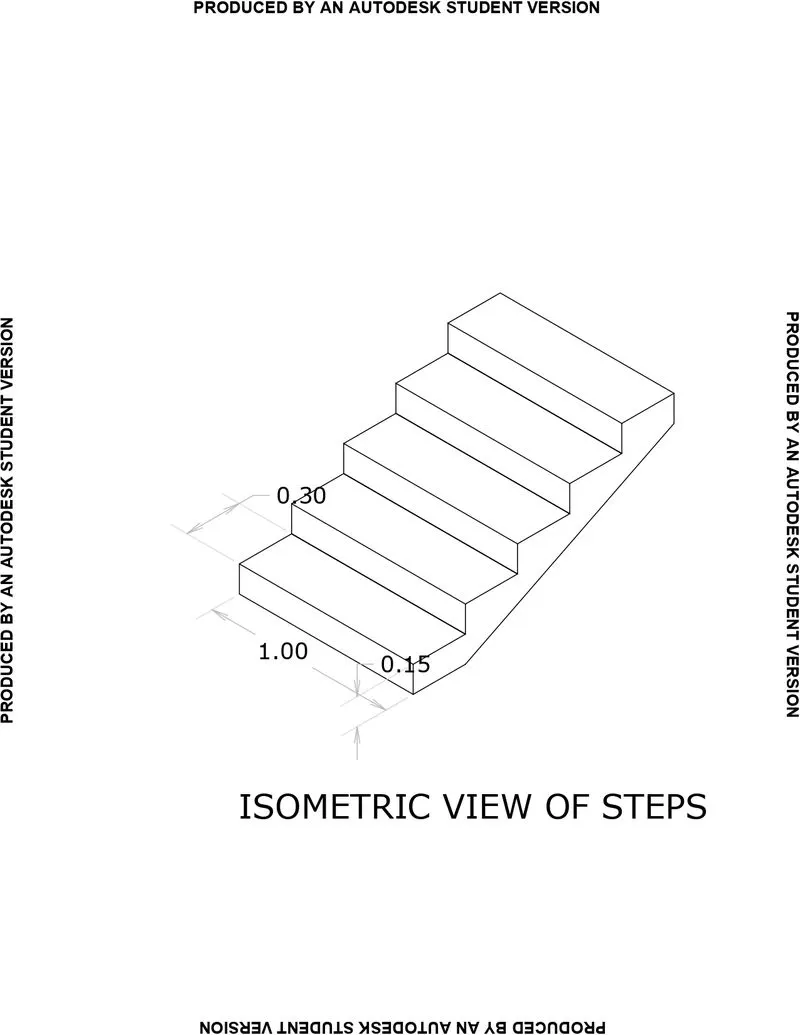
Procedure :-
- The Step by step procedure of drawing is as per following.
A.
- Type DS in command line and press enter.
- Unpick Snap On and Grid On Option.
- Tick on isometric snap in snap type.
- This will activates the isometric screen.
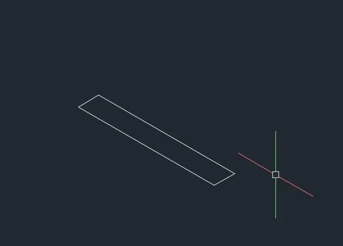
- Type PL in command line and press enter.
- Specify Start point A.
- Take isoplane Left.
- Specify Next Point : 1, Cursor towards NW.
- Take isoplane Right.
- Specify Next Point : 0.15, Cursor towards N.
- Specify Next Point : 1, Cursor towards S.
- Specify Next Point : 0.15, Cursor towards E.
B.
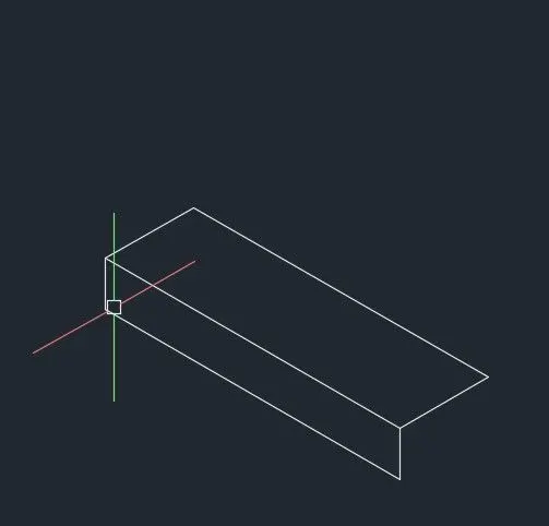
- Type PL in command line and press enter.
- Specify the first point of Polyline b.
- Take isoplane Top.
- Specify Next Point : 0.30, Cursor towards NE.
- Specify Next Point : 1, Cursor towards NS.
- Specify Next Point : 0.30, Cursor towards SW.
C.
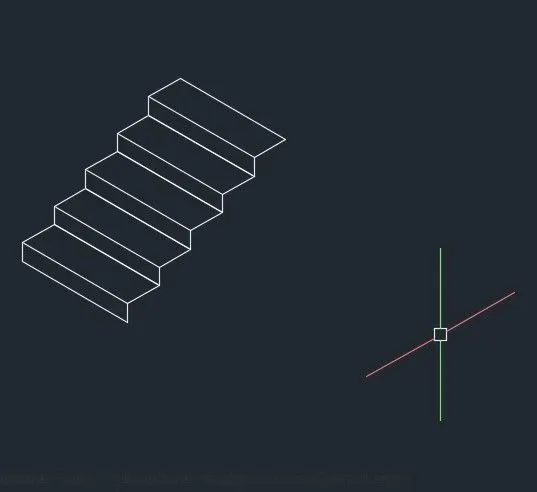
- Type CO in command line and press enter.
- Select the complete steps and press enter.
- Select B as a base point and place it 4 times at the positions c,d,e,f.
D.
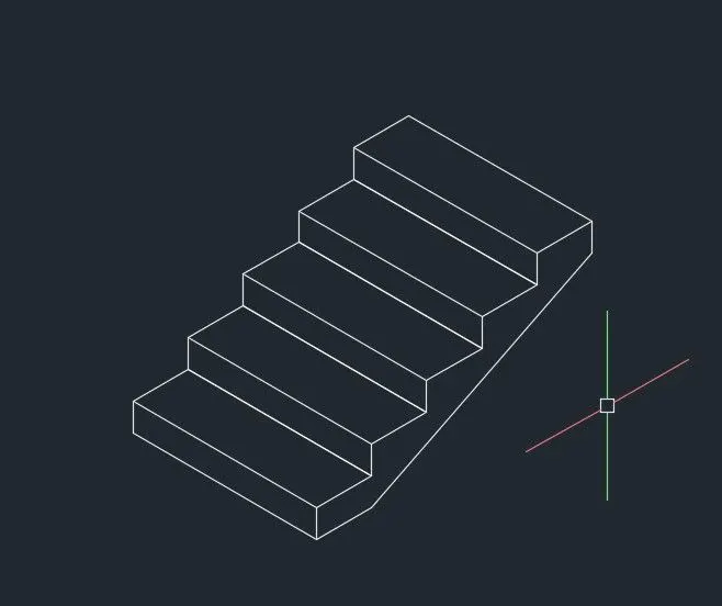
- Type L in command line and press enter.
- Specify Start Point G.
- Take isoplane Right.
- Specify Next Point : 0.15, Cursor towards S.
- Type L in command line and press enter.
- Specify Start Point H.
- Take isoplane Right.
- Specify Next Point : 0.30, Cursor towards NE.
- Type L in command line and press enter.
- Specify Start Point i.
- Specify Start Point j.
E.
- Give the dimensions as per drawing using dimension command for command bar.
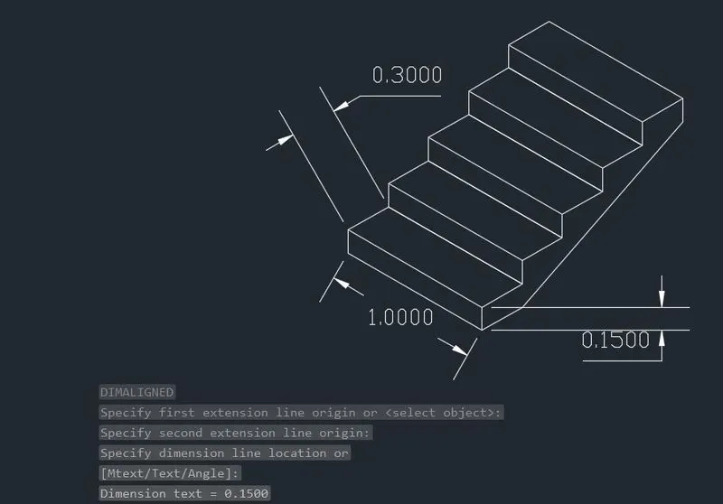
- Isometric views of Steps is Completed.
Drawing-6 :- Isometric views of Gable Wall :-
Procedure :-
- The Step by step procedure of drawing is as per following.
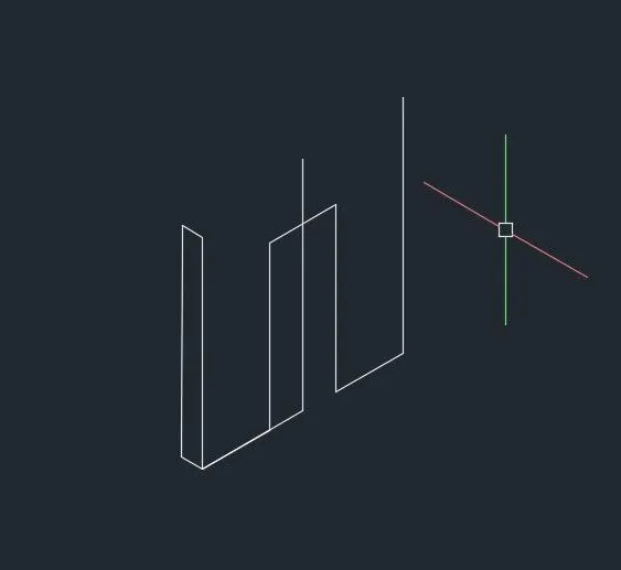
A.
- Type DS in command line and press enter.
- Unpick Snap On and Grid On Option.
- Tick on isometric snap in snap type.
- This will activates the isometric screen.
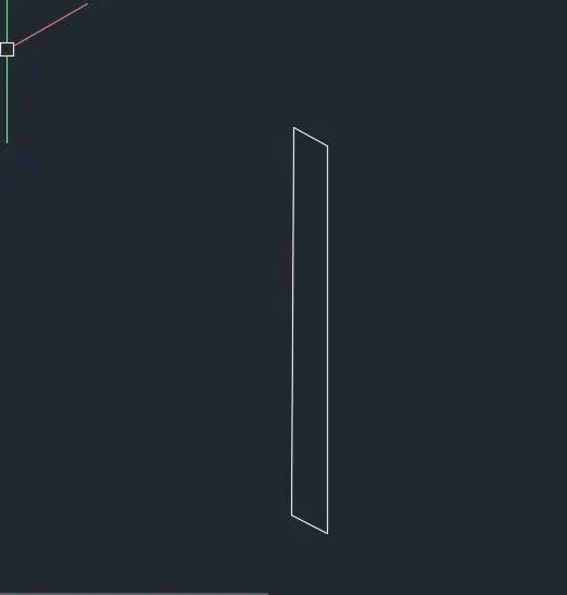
- Type L in command line and press enter.
- Specify Start point A.
- Take isoplane left.
- Specify Next Point : 0.30, Cursor towards NW.
- Specify Next Point : 3, Cursor towards N.
- Specify Next Point : 0.30, Cursor towards SE.
- Specify Next Point : 3, Cursor towards E.
B.
- Type L in command line and press enter.
- Specify Start point A.
- Take isoplane top.
- Specify Next Point : 1, Cursor towards NE.
- Specify Next Point : 1, Cursor towards NE.
- Specify Next Point : 1, Cursor towards NE.
- Delete Line BC.
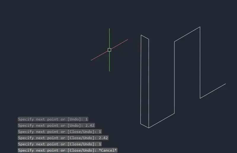
- Type L in command line and press enter.
- Specify Start point B.
- Take isoplane Right.
- Specify Next Point : 2.42, Cursor towards N.
- Take isoplane Top.
- Specify Next Point : 1, Cursor towards NE.
- Specify Next Point : 2.42, Cursor towards E.
C.
- Type L in command line and press enter.
- Specify Start point C.
- Take isoplane left.
- Specify Next Point : 0.30, Cursor towards NW.
- Take isoplane Right.
- Specify Next Point : 2.12, Cursor towards N.
D.
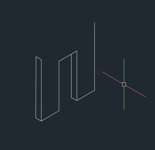
- Type L in command line and press enter.
- Specify Start point A.
- Take isoplane Top.
- Specify Next Point : 1.5, Cursor towards NE.
- Take isoplane Right.
- Specify Next Point : 3.25, Cursor towards N.
- Type L in command line and press enter.
- Specify Start point D.
- Take Isoplane left.
- Specify Next Point : 0.30, Cursor towards NW.
E.
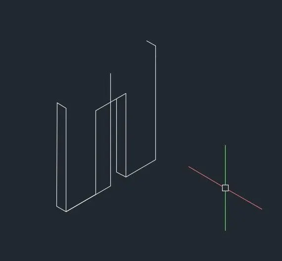
- Type L in command line and press enter.
- Specify the start point d.
- Specify the start point e.
- Specify the start point f.
F.
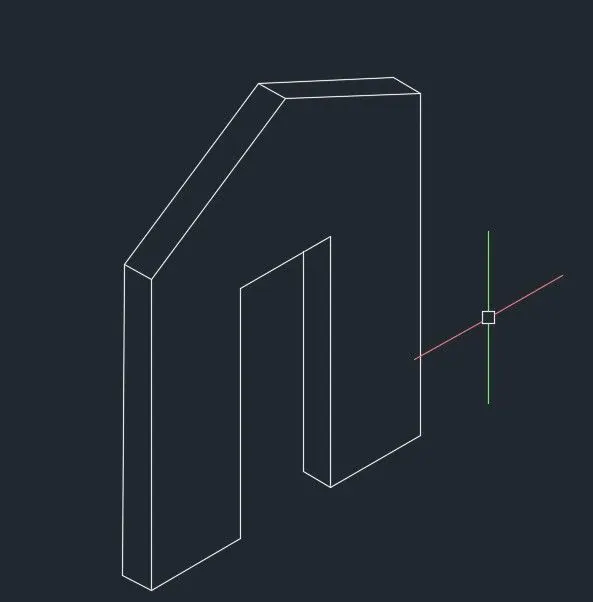
- Delete the line ag and eg.
- Type L in command line and press enter.
- Specify the start point h.
- Specify the start point i.
- Specify the start point j.
G.
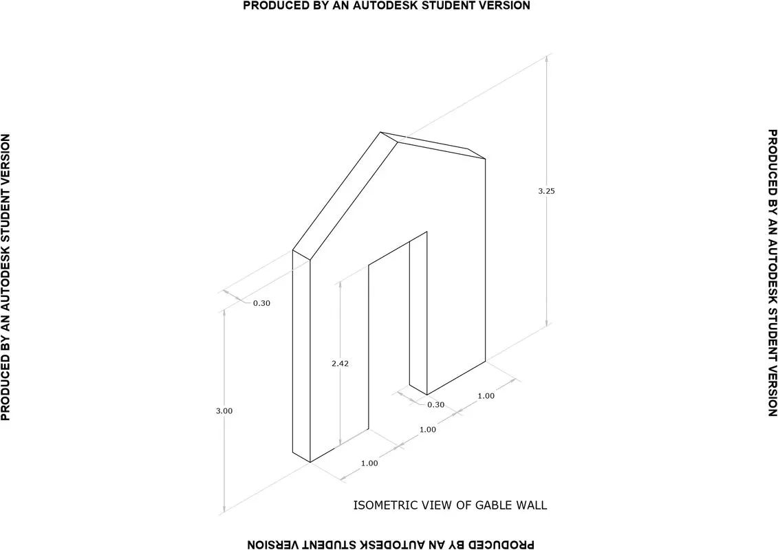
- Give the dimensions as per drawing using dimension command for command bar.
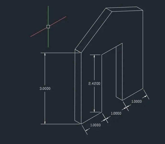
- Isometric views of Gable Wall is Completed.
Result :-
- Created a Floor plan, Footing detail and Isometric view using AutoCad and had a good understanding about various tools in Autocad like rectangle, polylines, modifications tools.