Steady Vs Unsteady flow over a cylinder
Steady and Unsteady Flow over Cylinder
Objective
To design the geometry and simulate the flow of air over the cylinder and to explain the Karman Vortex Street phenomenon.
3D Model
The 3D model comprises of the 2D cylinder and the boundary conditions such that the vortex shedding could be clearly visible behind the cylinder. The conditions for the boundary conditions are:
Inlet Boundary = 10 × Dcyl (m)
Outlet Boundary = 20 × Dcyl (m)
Symmetric Wall = 3 + Dcyl (m)
Where, Dcyl = 2 m
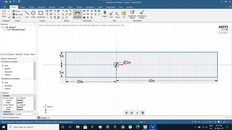
Fig.1. Cylinder and Boundary Geometry
Mesh Details
Finer element sizes allow us to visualize vortex shedding when it occurs even at lower inlet velocities. Mesh size of 0.075 m is being used throughout the analysis. Th cylinder wall is divided into 36 divisions, and inflation of 10 layers with 1.2 growth rate is used at the cylinder wall to obtain uniform mesh and smooth contours at the boundary. The high element quality, orthogonal quality and the lowest skewness of element depicts a good mesh being obtained.
Table 1: Mesh Details
|
PARAMETERS |
SPECIFICATIONS |
|
MESH TYPE |
ALL QUAD |
|
MESH SIZE |
0.075 m |
|
ELEMENTS |
105419 |
|
NODES |
106377 |
|
INFLATION LAYER |
10 |
|
INFLATION GROWTH RATE |
1.2 |
|
EDGE SIZING – NUMBER OF DIVISIONS |
36 |
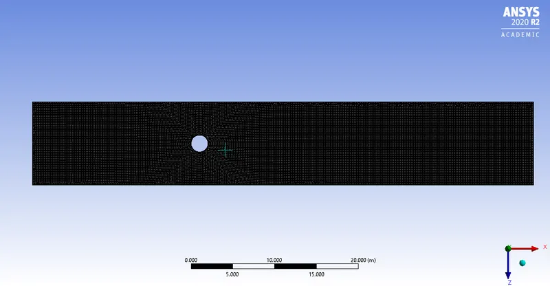
Fig.2.1. Fluid Volume Mesh
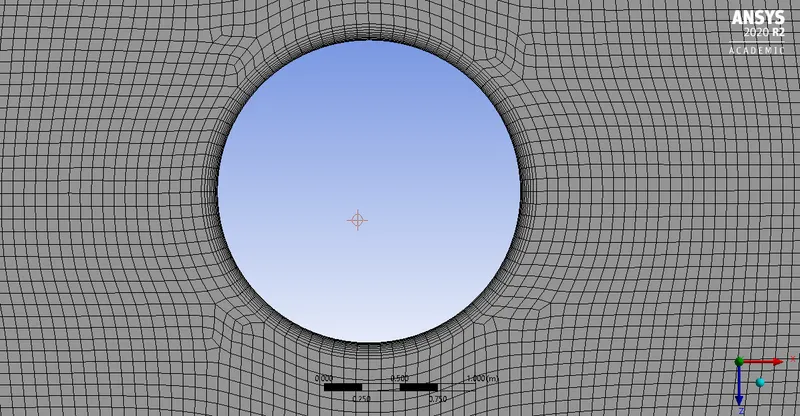
Fig.2.2. Inflation Layer
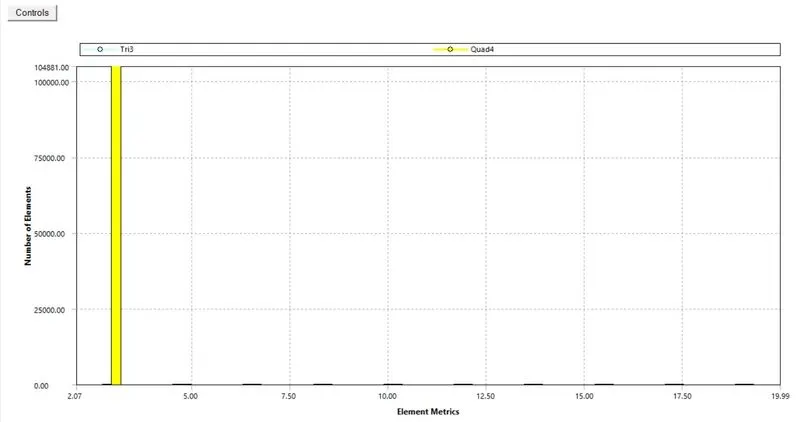
Fig.2.3. Element Quality
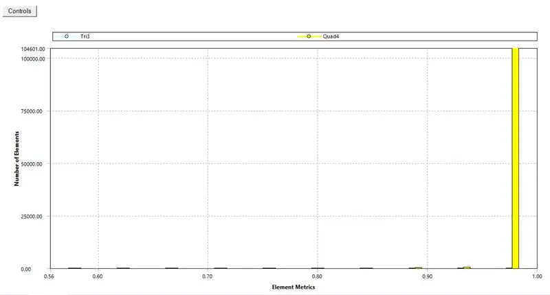
Fig.2.4. Orthogonal Quality
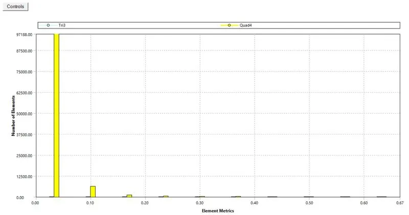
Fig.2.5. Skewness
Material Properties
Air is chosen as the fluid passing through the cylinder, having its default values.
Density (ρ) = 1.225 kg/m3
Reynold’s Number (Re) = 10, 100, 1000, 10000, 100000
Viscosity (ν) = 1.7894×10⁻⁵ kg/m-s
Boundary Conditions
To obtain various Reynold’s Number, the fluid inlet velocity was varied. The initial conditions are mentioned below:
Inlet velocity (v) = 7.304×10⁻⁵ to 7.304×10⁻¹ m/s
Outlet pressure = 0 Pa
Model Equations
Laminar and K-Ω SST were used to determine the steady and unsteady flow conditions respectively, around the cylinder. For higher Reynold’s Number, K-Ω SST model equations were used as it provides detailed contours of various parameters in the cylinder wall boundary.
Results
Case 1: Calculation of Strouhal Number for Re = 100 under steady and unsteady conditions.
Steady Condition
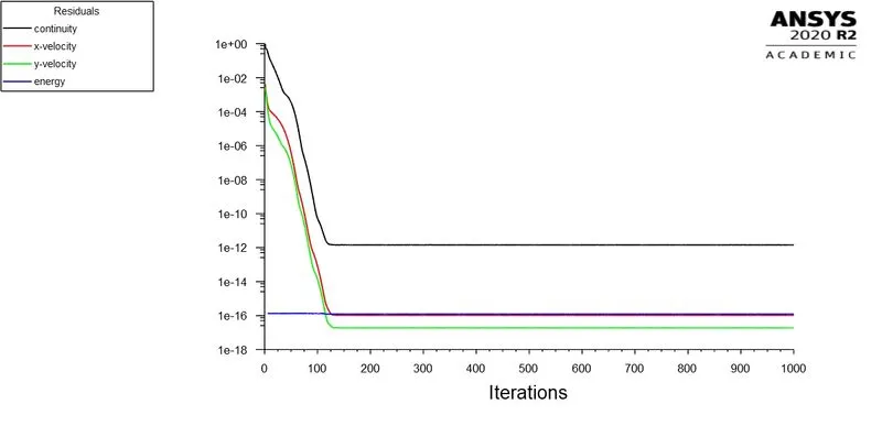
Residual
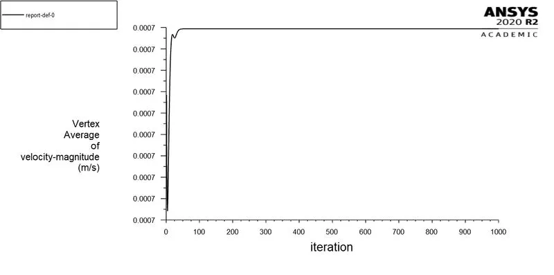
Vertex Averaged Velocity Magnitude
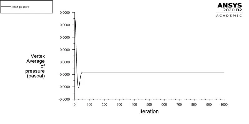
Vertex Averaged Pressure
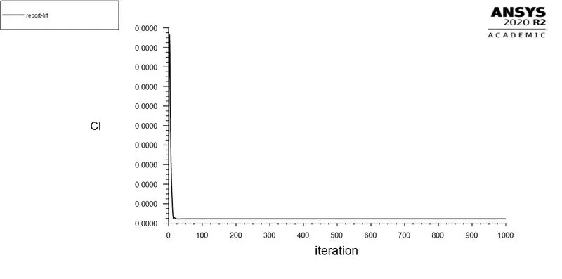
Coefficient of Lift
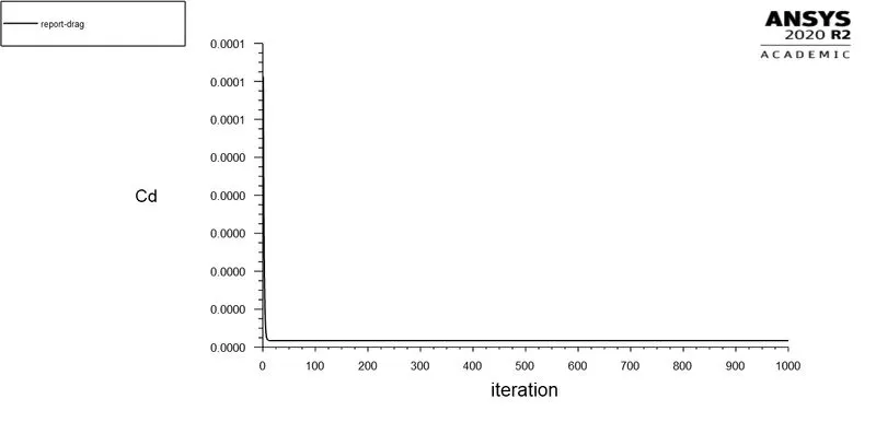
Coefficient of Drag
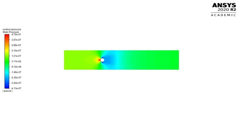
Pressure Contour
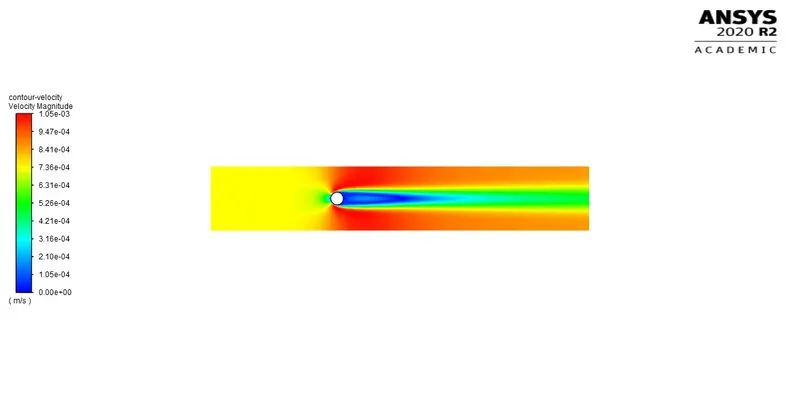
Velocity Contour
Lift Coefficient Frequency
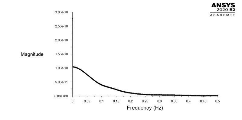
Under steady conditions, the coefficient of lift doesn’t oscillate to provide a frequency. Thus, Strouhal Number is zero.
Frequency (f) = 0 Hz
Diameter (d) = 2 m
Fluid Velocity (u) = 7.3037×10⁻⁴ m/s
St = = 0
Unsteady Condition
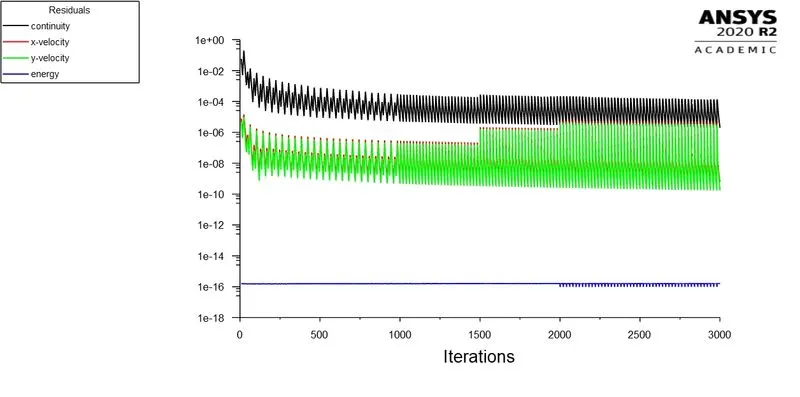
Residual
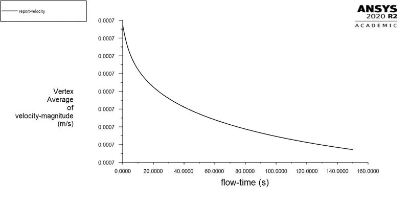
Vertex Averaged Velocity Magnitude
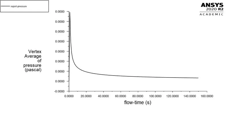
Vertex Averaged Pressure
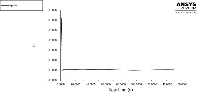
Coefficient of Lift
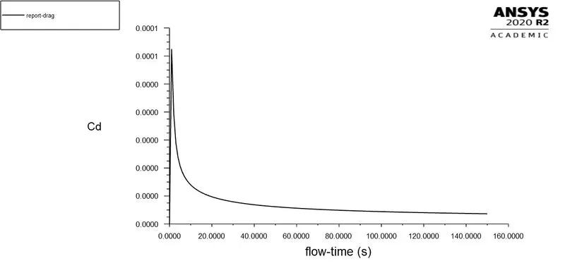
Coefficient of Drag
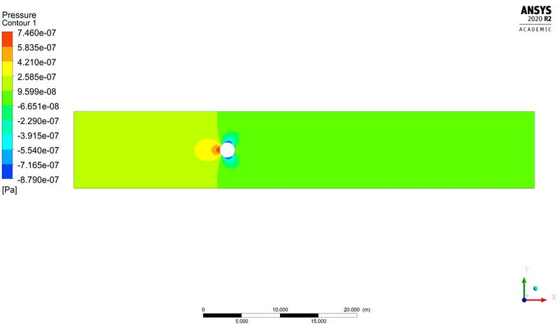
Pressure Contour
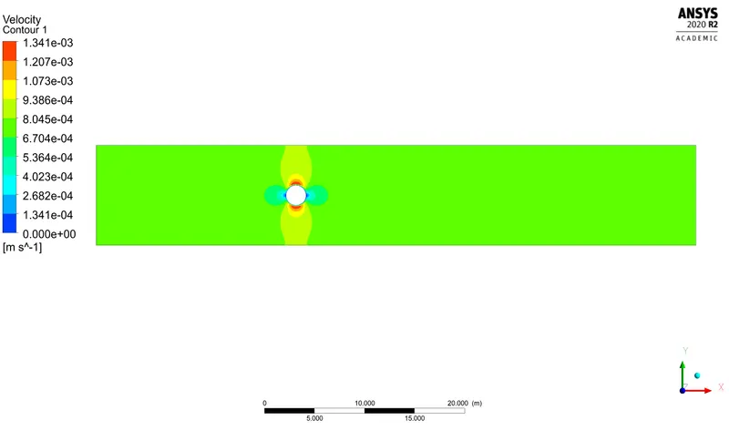
Velocity Contour
Lift Coefficient Frequency
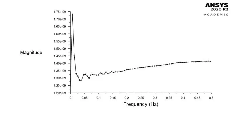
Under unsteady conditions, the coefficient of lift oscillates to provide a frequency.
Frequency (f) = 1.425×10⁻⁹ Hz
Diameter (d) = 2 m
Fluid Velocity (u) = 7.3037×10⁻⁴ m/s
St = = = 3.902×10⁻⁶
Case 2: Calculation of coefficient of lift and drag with Re = 10, 100, 1000, 10000, 100000.
Re = 10
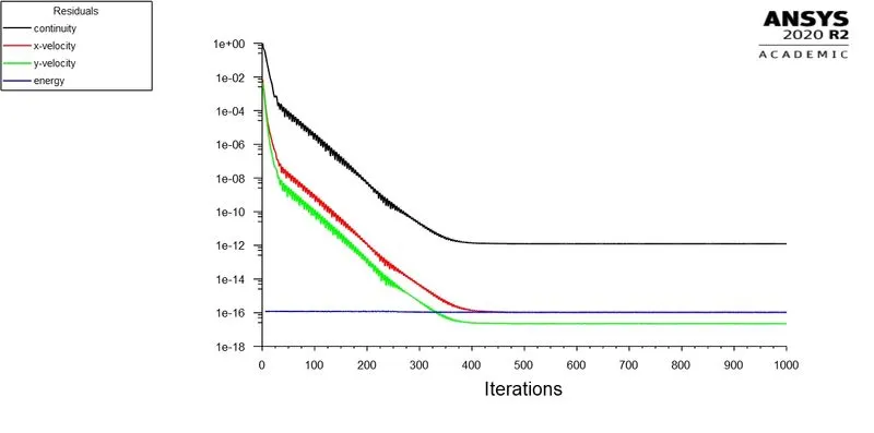
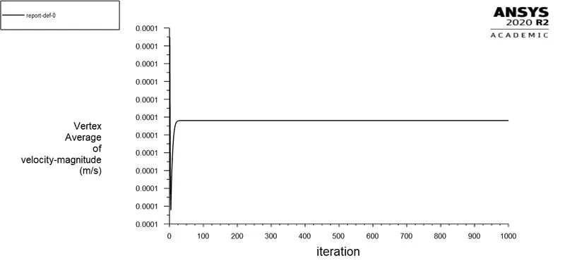
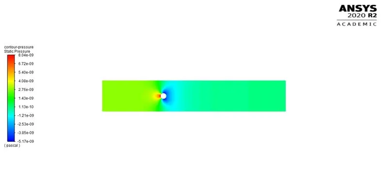
To obtain Re = 10, the inlet fluid velocity is 7.3037×10⁻⁵ m/s. The calculation was done for 1000 iterations.
Residuals
Vertex Averaged Velocity Magnitude
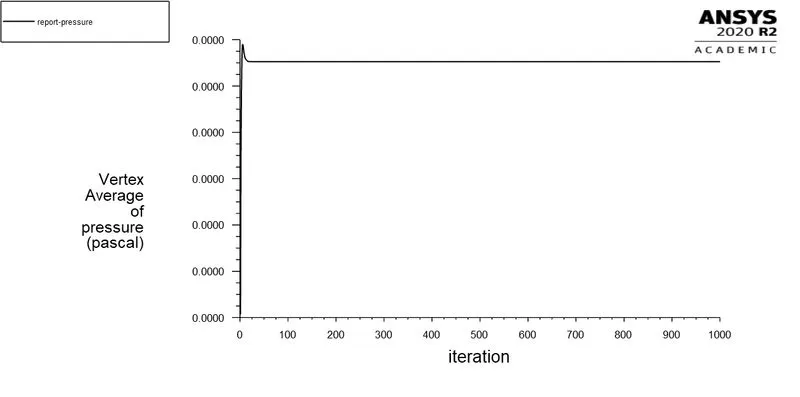
Vertex Averaged Pressure
Lift Coefficient
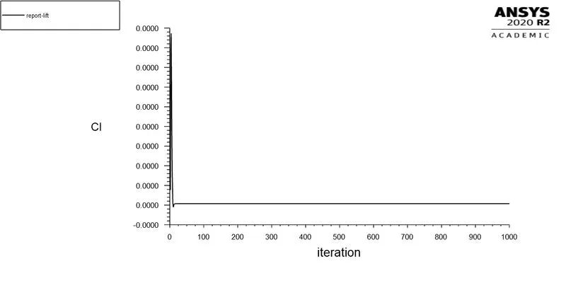
The lift coefficient (CL) obtained is 0.
Drag Coefficient
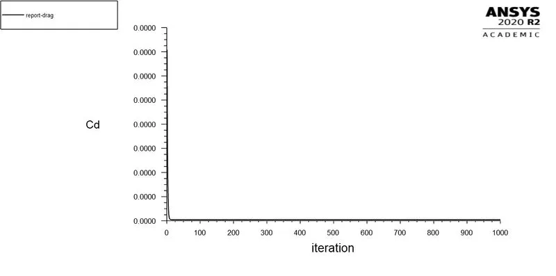
The drag coefficient (CD) obtained is 0.
Pressure Contour
Velocity Contour
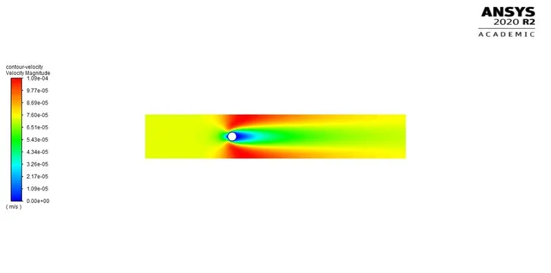
Re = 100
To obtain Re = 100, the inlet fluid velocity is 7.3037×10⁻⁴ m/s. The calculation was done for 1000 iterations.
Residuals
Vertex Averaged Velocity Magnitude
Vertex Averaged Pressure
Lift Coefficient
The lift coefficient (CL) obtained is 0.
Drag Coefficient
The drag coefficient (CD) obtained is 0.
Pressure Contour
Velocity Contour
Re = 1000
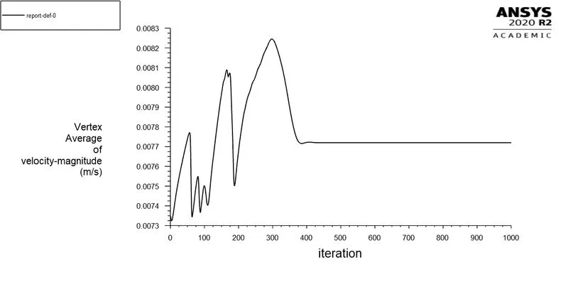
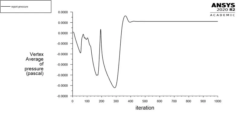
To obtain Re = 1000, the inlet fluid velocity is 7.3037×10⁻³ m/s. The calculation was done for 1000 iterations.
Residuals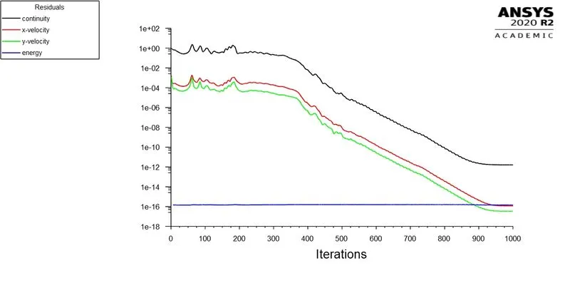
Vertex Averaged Velocity Magnitude
Vertex Averaged Pressure
Lift Coefficient
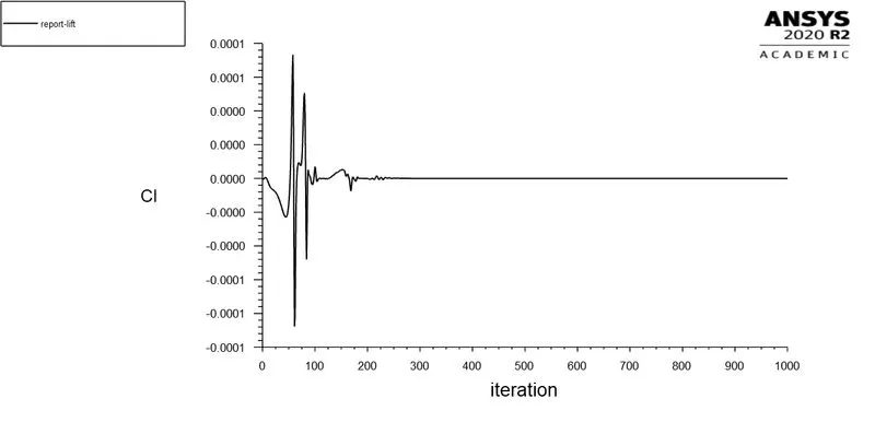
The lift coefficient (CL) obtained is 0.
Drag Coefficient
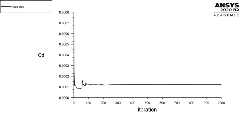
The drag coefficient (CD) obtained is 0.000125
Pressure Contour
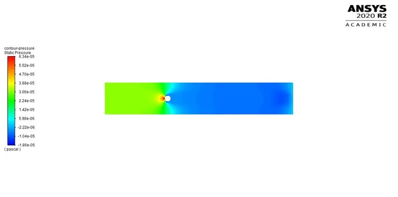
Velocity Contour
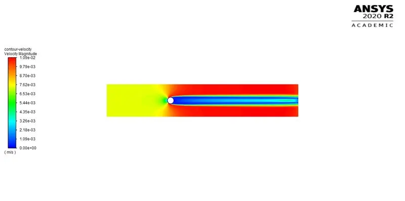
Re = 10000
- Laminar
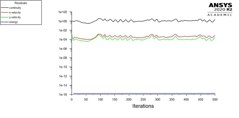
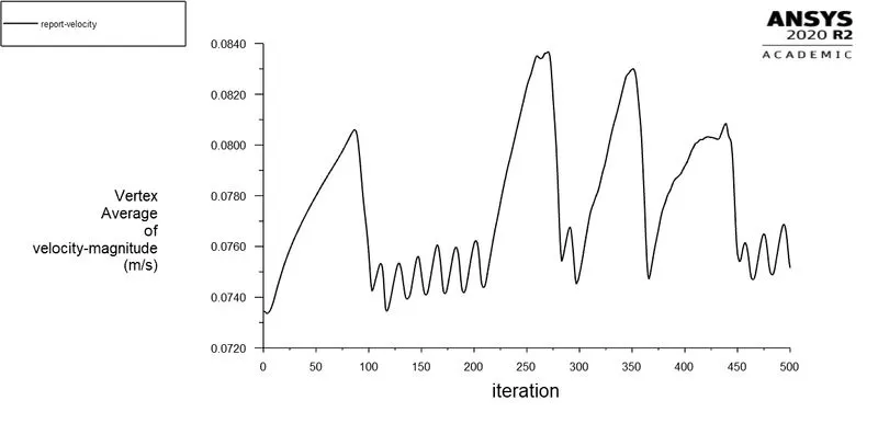
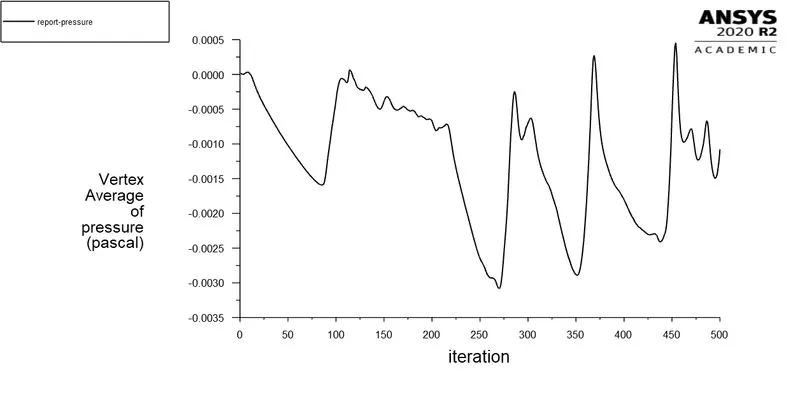
To obtain Re = 10000, the inlet fluid velocity is 7.3037×10⁻² m/s. The calculation was done for 500 iterations.
Residuals
Vertex Averaged Velocity Magnitude
Vertex Averaged Pressure
Lift Coefficient
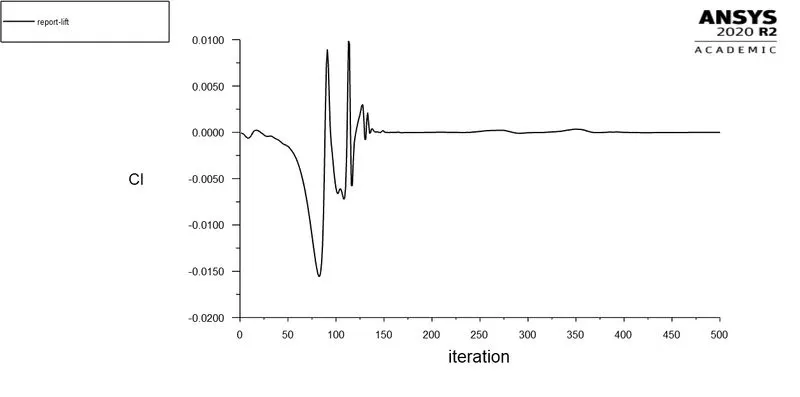
The lift coefficient (CL) obtained is 0.001
Drag Coefficient
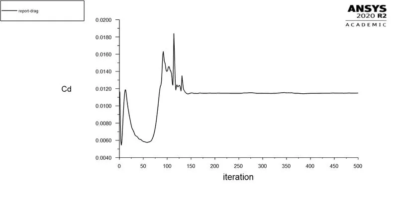
The drag coefficient (CD) obtained is 0.0120
Pressure Contour
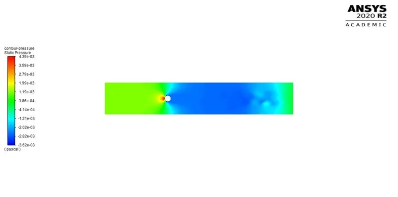
Velocity Contour
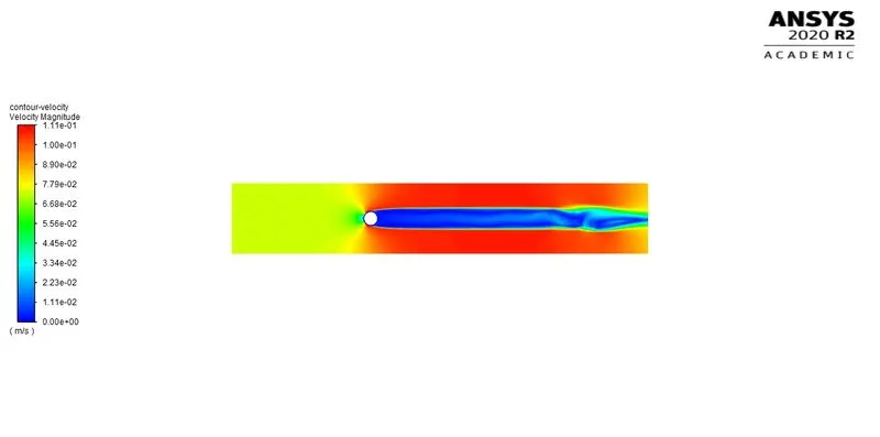
- K-Ω SST
To obtain Re = 10000, the inlet fluid velocity is 7.3037×10⁻² m/s. The calculation was done for 1000 iterations.
Residuals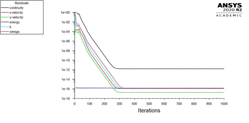
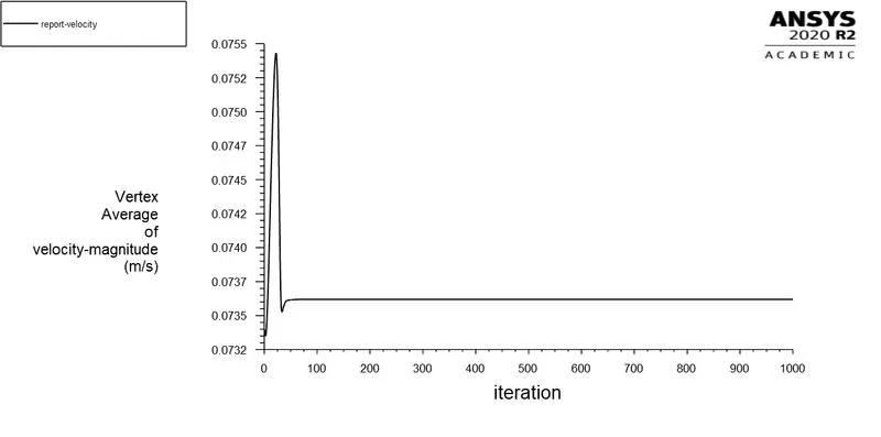
Vertex Averaged Velocity Magnitude
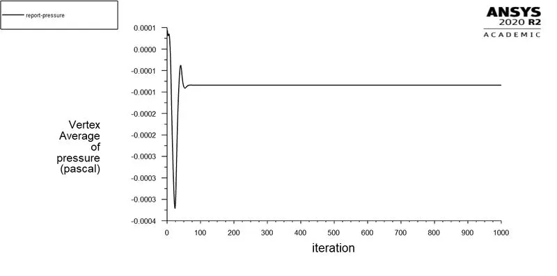
Vertex Averaged Pressure
Lift Coefficient
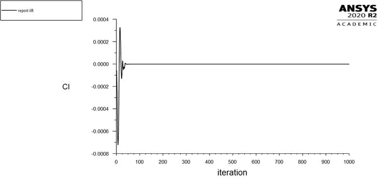
The lift coefficient (CL) obtained is 0.
Drag Coefficient
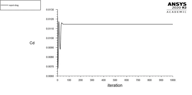
The drag coefficient (CD) obtained is 0.0115
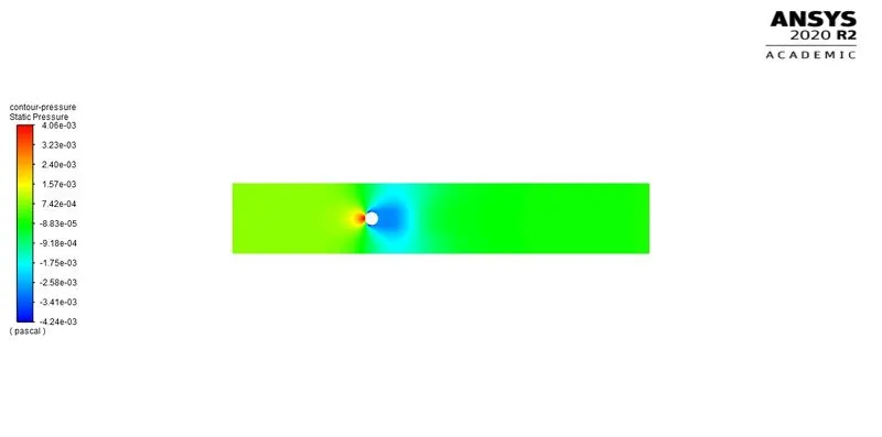
Pressure Contour
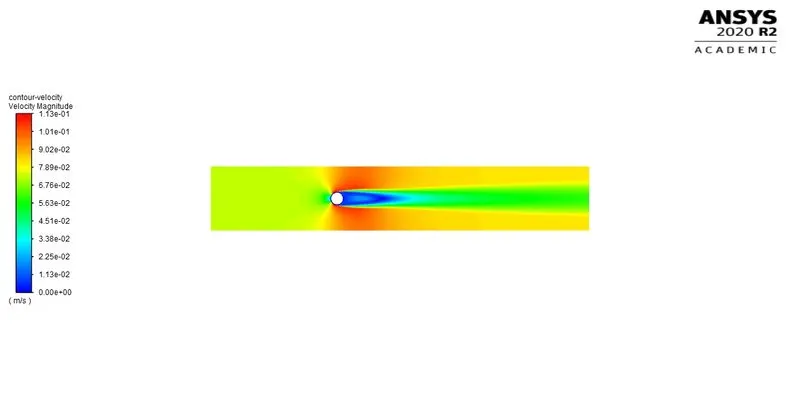
Velocity Contour
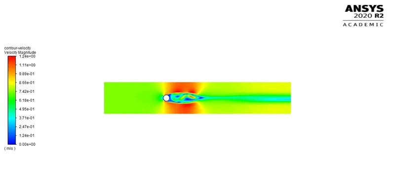
Re = 100000
- Laminar
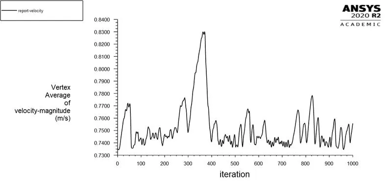
To obtain Re = 100000, the inlet fluid velocity is 7.3037×10⁻¹ m/s. The calculation was done for 1000 iterations.
Residuals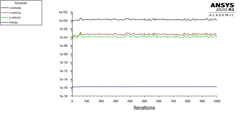
Vertex Averaged Velocity Magnitude
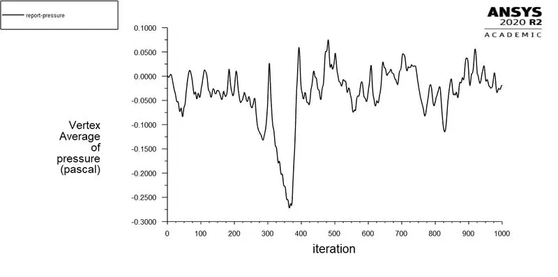
Vertex Averaged Pressure
Lift Coefficient
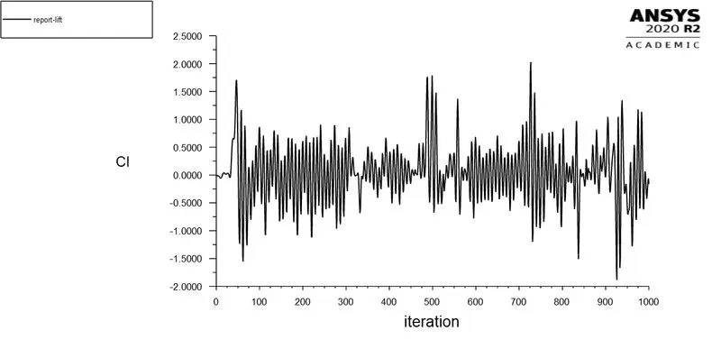
The lift coefficient (CL) obtained is 0.
Drag Coefficient
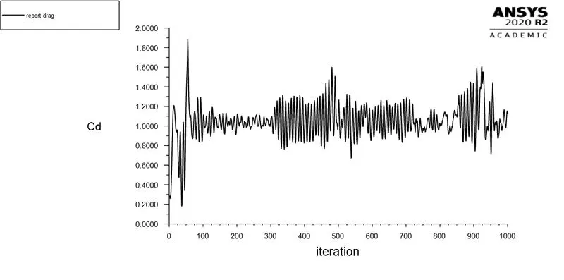
The drag coefficient (CD) obtained is 1.
Pressure Contour
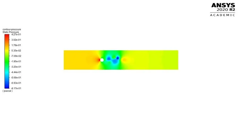
Velocity Contour
- K-Ω SST
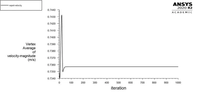
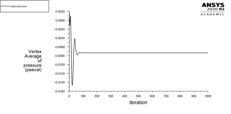
To obtain Re = 100000, the inlet fluid velocity is 7.3037×10⁻¹ m/s. The calculation was done for 1000 iterations.
Residuals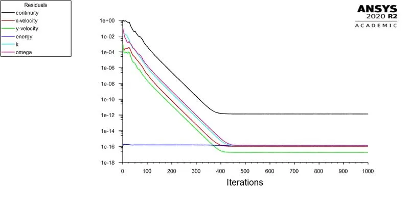
Vertex Averaged Velocity Magnitude
Vertex Averaged Pressure
Lift Coefficient
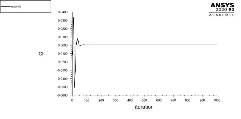
The lift coefficient (CL) obtained is 0.
Drag Coefficient
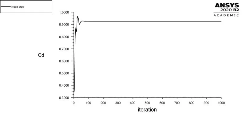
The drag coefficient (CD) obtained is 0.925
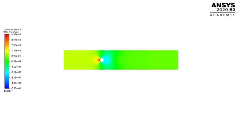
Pressure Contour
Velocity Contour
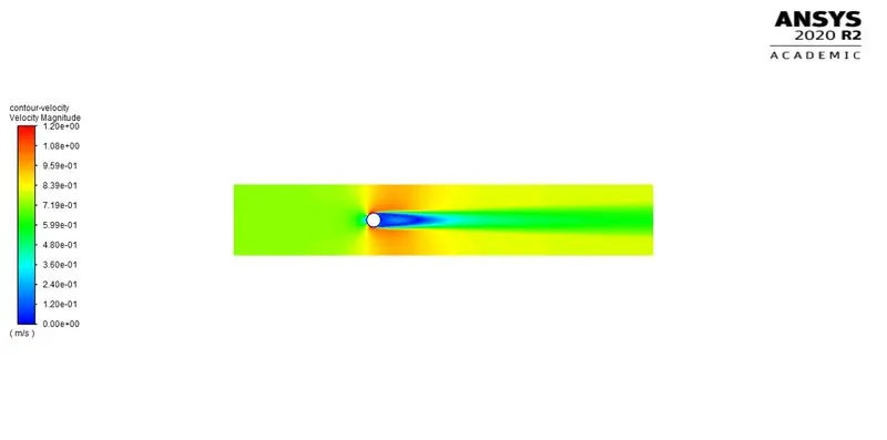
From the above contours and plots, the vortex shedding takes place when Reynold’s Number is 10000 and 100000. It is also seen that the coefficients of lift and drag varies when Reynold’s Number increases.
|
REYNOLD’S NUMBER |
MODEL EQUATION |
COEFFICIENT OF LIFT (CL) |
COEFFICIENT OF DRAG (CD) |
|
10 |
LAMINAR |
0 |
0 |
|
100 |
LAMINAR |
0 |
0 |
|
1000 |
LAMINAR |
0 |
0.000125 |
|
10000 |
LAMINAR |
0.001 |
0.0120 |
|
K-Ω SST |
0.0115 |
0 |
|
|
100000 |
LAMINAR |
0 |
1 |
|
K-Ω SST |
0 |
0.925 |
Conclusion
From the plots and contours obtained, its evident that laminar viscous model provides vortex shedding at high Reynold’s Number. As the cylinder wall is symmetric, the lift and drag coefficients obtained were low, resulting in lower Strouhal Number. When the Reynold’s Number is below 1000, vortex shedding was not observed, but was observed when it increases till 100000.