STATE FLOW LOGIC FOR "WASHING MACHINE" USING SIMULINK SOFTWARE
AIM-1
Implement control logic of a “washing machine” using Stateflow as per given sequence:
- If the power supply is available, the system gets activated
- If the Water supply is not available, stop the process & indicate through LED
- Soaking time should be 200s followed by Washing time of 100s.
- Then rinsing happens for next 20s & dryer runs for 50s
After all the processes have completed turn on the finished LED
REQUIREMENTS
MATLAB & SIMULINK softwares
Simulink - is a graphical user interface for modeling and simulation of block schematics. The core of the Matlab is used to compute the simulating results. Simulink is primarily used for modeling dynamic systems. Simulink’s libraries offer a plenty of blocks useful for modeling complex systems. With help of integrating methods, we can simulate the system and analyze it in time.
Simscape – is a library of basic real world mechanics, hydraulics and electronics components. System, built from these blocks, is modeled from view of energy flow. Model works directly with physical parameters, so it approximates good real systems. Simscape generates differential equations from the modeled system that can communicate with other components from Matlab/Simulink after the simulation has been started.
PROCEDURE
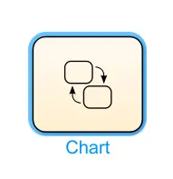
- The first step is to create a stateflow chart in the simulink environment. It is done by double clicking on the simulink environment and searching for 'chart' or draging it from the simulink library.
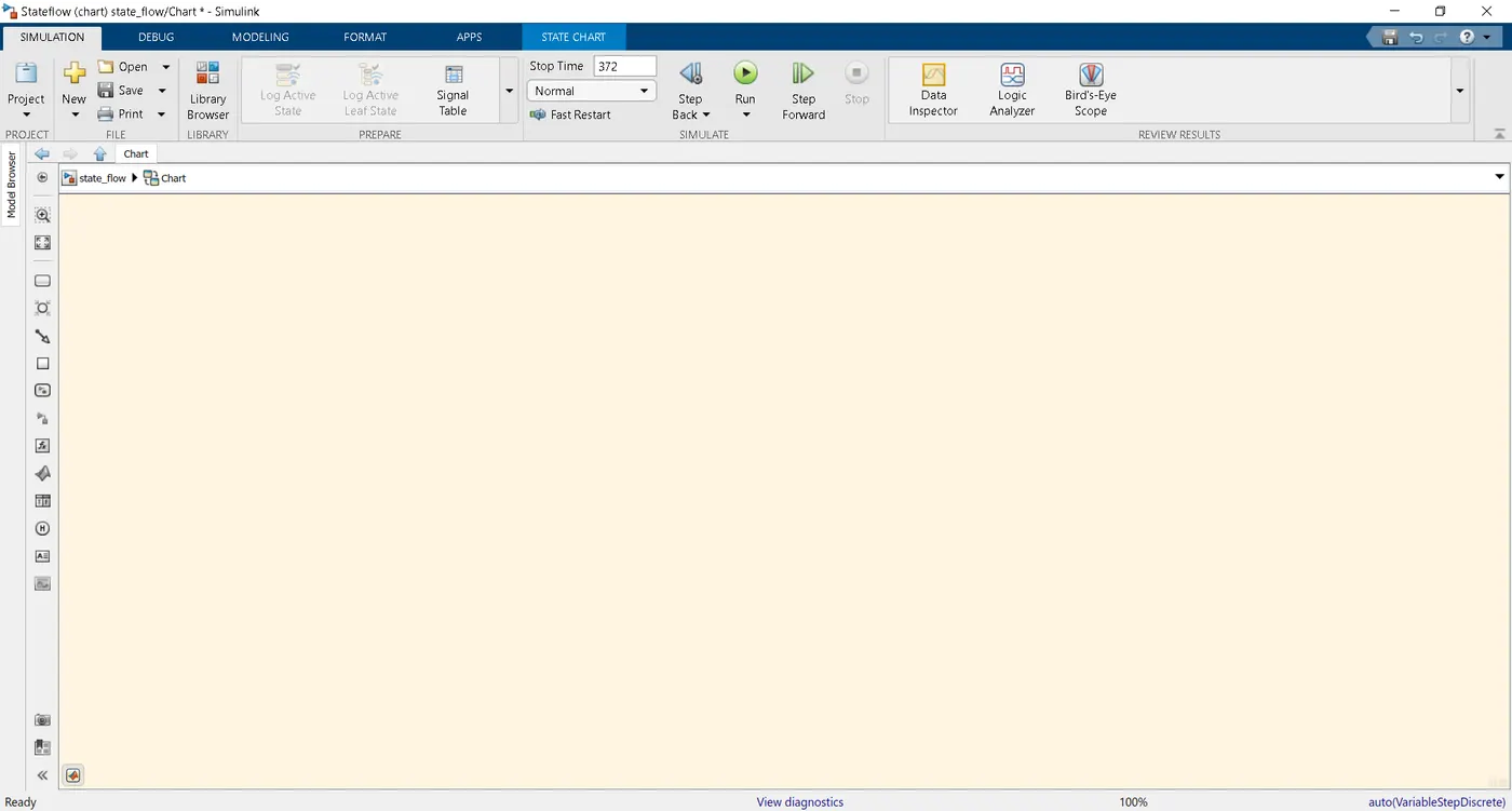
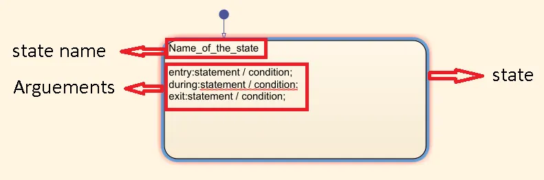
- The statflow chart environment looks like as shown below:-
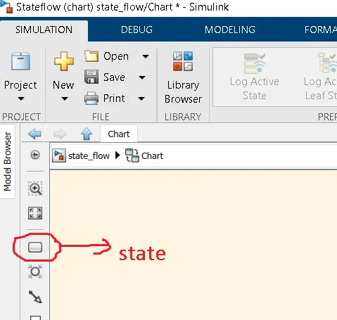
- Then we will create states as per the sequence by dragging the below shown icon (i.e. icon is annotation for better understanding).
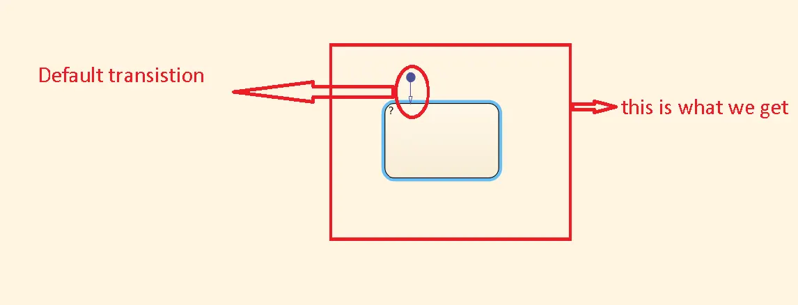
 ⇒">⇒⇒
⇒">⇒⇒
- Now as per the sequence provided, i have designed the chart as shown below:-
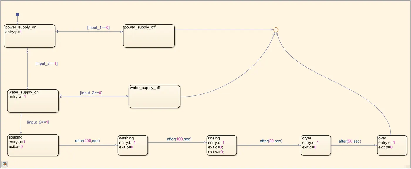
Explanation:-
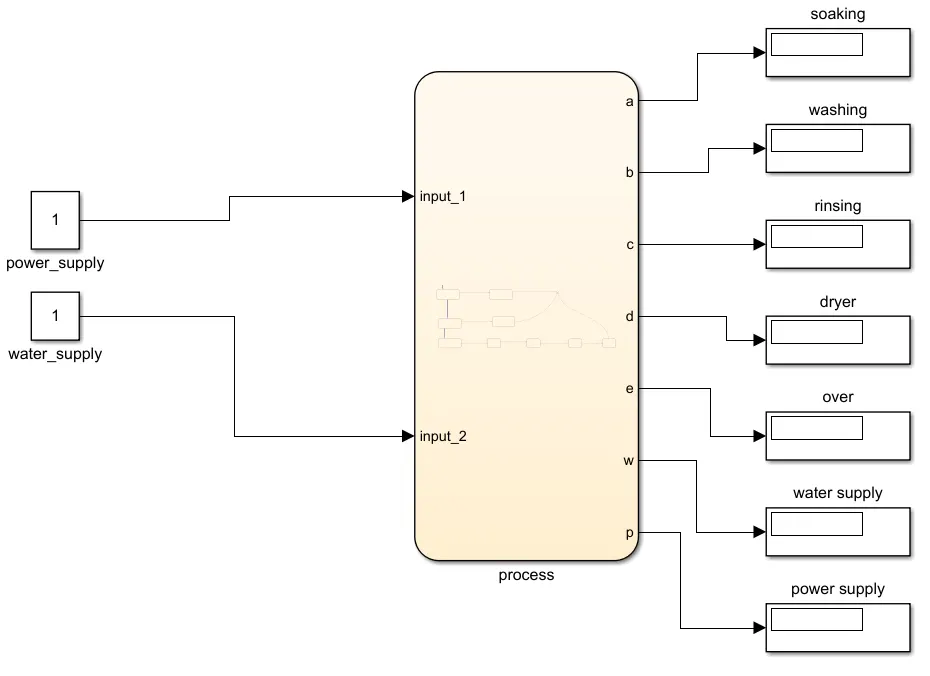
- Here the input signals provided into the chart are 2. One is for the power supply (i.e. input_1) and the other is for the water supply (i.e. input_2).
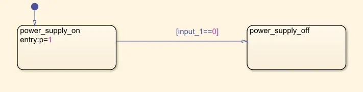
- We create the first default state is the power_supply_on state, followed by power_supply_off state. The sequence has been numbred 1 for the later state .It will be executed if input_1 signal becomes 0.
- Then we attach the power supply ON state to the power supply on state directly, then it will go and check for water supply. The condition for that is input_2==1 and if input_2==0, then it meas no water supply present.
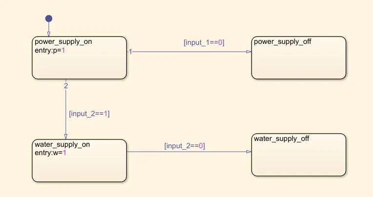
NOTE:- Here i have given the arguements only in power_supply_on and water_supply_on (i.e. p=1 and w=1 respectively). This is for cutting the power supply when all the processes are complete and also cutting the water supply after the rinsing process (i.e. dryer process doesn't need water, but requires power supply). These arguements are given for showcasing the output values on the display blocks given as the output of the stateflow chart. You will understand when output procedure is explained.
- Now we will define the processes such as soaking for 200sec, washing for 100sec, rinsing for 20sec, dryer for 50sec and at last the end state is also defined. The condition for transition from water_supply_on to soaking state is input_2==1.

NOTE-1:- In each of the above states the output has to show 1 as the process's ON value and 0 as the process's OFF value. The time delay provided is not as condition or action statements, but as a message to the stateflow chart.
NOTE-2:- Also, we have to provide w=o and p=0 in the rinsing and over states, repectively. Because the power supply is not required after the over state and water supply is not required from dryer state.
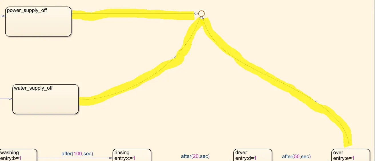
- There should not be any states dangling, for that we connect all the hanging states to one comon node.
- Then we have to give the defined variables inside the chart its scope and type (i.e. p,w,a,b,c,d and e). It can be given from the signal pane window.
- Now we will define the input and output blocks for the chart.
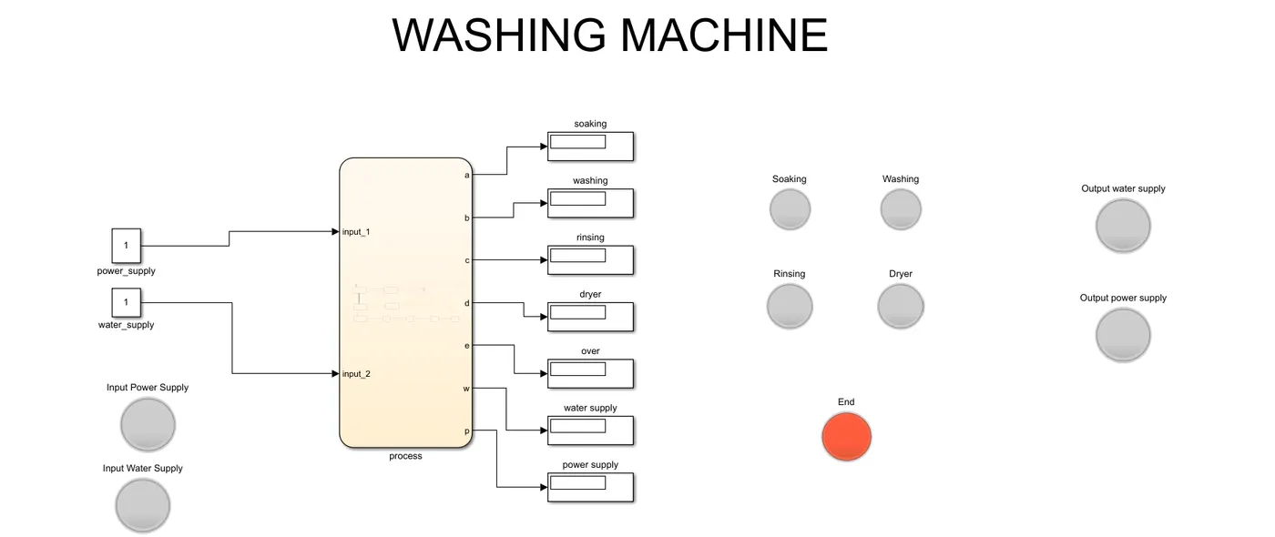
- Also we have to indicate each process using a lamp for better understanding. Hence we defined 9 lamps and have connected them to their respective sates and has been labelled.
COMPLETE DESIGN
OUTPUT
1. WHEN POWER SUPPLY IS GIVEN & WATER SUPPLY IS NOT GIVEN

2.WHEN POWER SUPPLY AND WATER SUPLY IS GIVEN
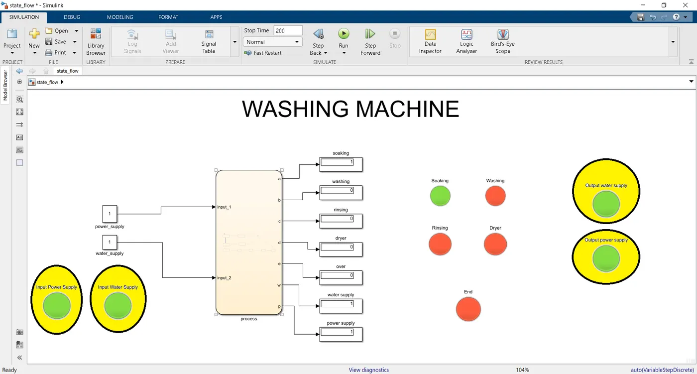
3.WHEN POWER SUPPLY AND WATER SUPLLY IS GIVEN, FOLLOWED BY SOAKING PROCESS STARTS
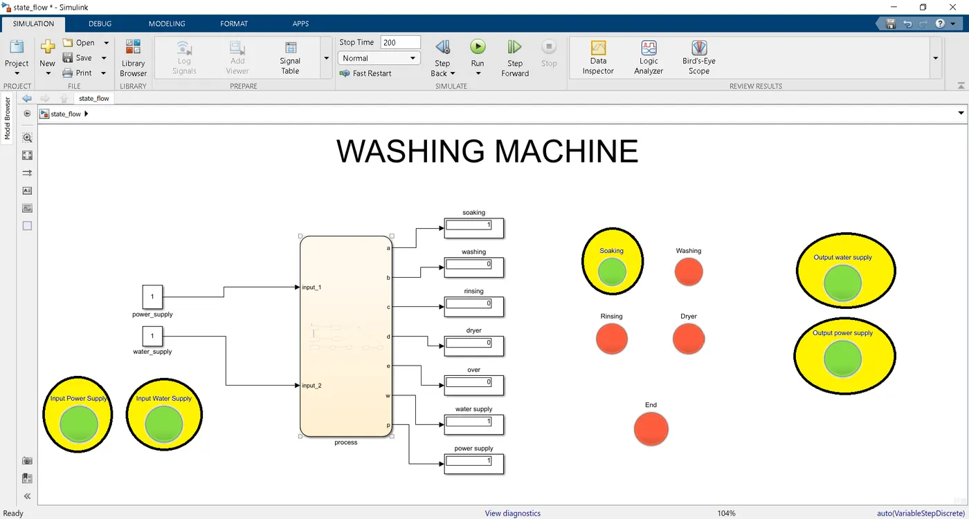
4.WHEN POWER SUPPLY AND WATER SUPLLY IS GIVEN, FOLLOWED BY SOAKING PROCESS ENDS AND WASHING PROCESS STARTS
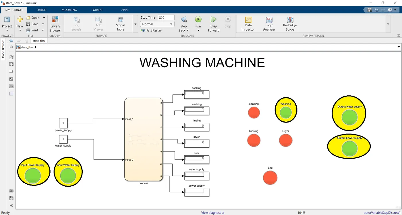
5.WHEN POWER SUPPLY AND WATER SUPLLY IS GIVEN, FOLLOWED BY SOAKING PROCESS AND WASHING PROCESS ENDS AND RINSING PROCESS STARTS
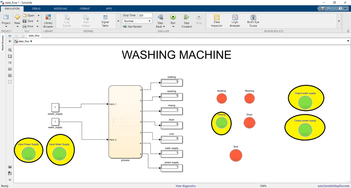
6.WHEN POWER SUPPLY AND WATER SUPLLY IS GIVEN, FOLLOWED BY SOAKING PROCESS, WASHING PROCESS, RINSING PROCESS ENDS AND DRYER PROCESS STARTS
NOTE:- Here the output water supply lamp is in OFF state whereas the output power supply is in ON state.
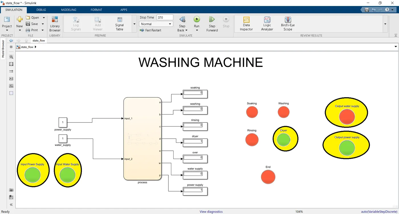
7.WHEN POWER SUPPLY AND WATER SUPLLY IS GIVEN, FOLLOWED BY SOAKING PROCESS, WASHING PROCESS, RINSING PROCESS DRYER PROCESS ENDS AND THE PROCESS EXECUTES THE 'END' STATE
NOTE:-Here the END and the output power supply is in ON state, because power is neede for these lamps to work.
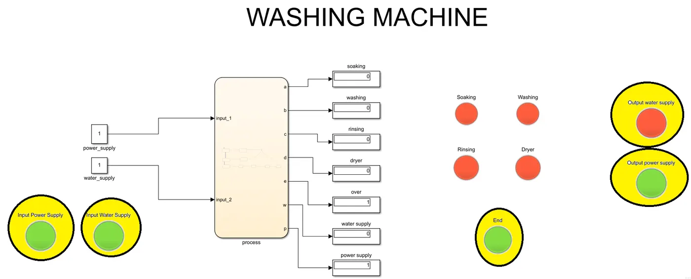
RESULT:- The washing machine logic is successfully implemented and executed.
- Sarangarjan VijayraghavanNice work Ajay.