Speed vs Torque Characteristics of Frequency Controlled using MATLAB
Objective
> Explain in brief about operation of BLDC motor.
> The equivalent circuit network of induction motor MATLAB model.
> To calculate the ratio of starting torque at half voltage & frequency to rated values of a 3 phase, 50 Hz induction motor, represented by equivalent circuit constants X1 = X2 = 0.1 ohm and R1 = R2 = 0.2 ohm is operated at half of rated voltage and frequency.
> Make a MATLAB script file which will plot speed torque characteristics for frequency control method.
Brief explanation about operation of BLDC motor
BLDC motor
> A brushless DC motor (known as BLDC) is a permanent magnet synchronous electric motor which is driven by direct current (DC) electricity
> BLDC motors are superior to brushed DC motors in many ways, such as ability to operate at high speeds, high efficiency, and better heat dissipation.
> BLDC motor incorporates a permanent magnet in the rotor. The number of poles in the rotor can vary from 2 to 8 pole pairs with alternate south and north poles depending on the application requirement.
> Unlike brushed type DC motor, wherein the brushes make the mechanical contact with commutator on the rotor so as to form an electric path between a DC electric source and rotor armature windings, BLDC motor employs electrical commutation with permanent magnet rotor and a stator with a sequence of coils. In this motor, permanent magnet rotates and current carrying conductors are fixed.
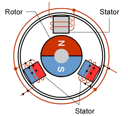
Operation
> The armature coils are switched electronically by transistors or silicone controlled rectifiers at the correct rotor position in such a way that armature field is in space quadrature with the rotor field poles. Hence the force acting on the rotor causes it to rotate.
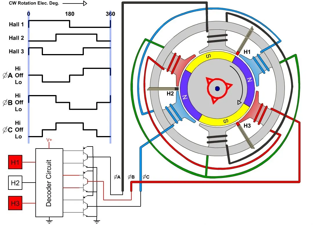
> Hall sensors or rotary encoders are most commonly used to sense the position of the rotor and are positioned around the stator. The rotor position feedback from the sensor helps to determine when to switch the armature current.
> In the below image H1, H2 and H3 represents the hall sensors. The phases A, B and C are varied from low to high according to the requirment.
> The figure below shows the simple BLDC motor drive circuit which consists of MOSFET bridge (also called as inverter bridge), electronic controller, hall effect sensor and BLDC motor.
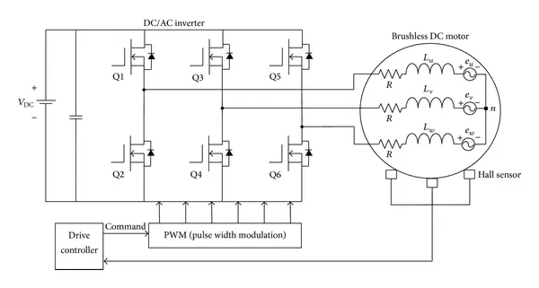
> From the circuit it is seen that the input from the hall sensors are given to the drive controller which inturn modulates the DC supply accordingly with the use of mosfets to make the rotor rotate.
Advantages
BLDC motor has several advantages over conventional DC motors.
> It has no mechanical commutator and associated problems.
> High efficiency due to the use of permanent magnet rotor.
> High speed of operation even in loaded and unloaded conditions due to the absence of brushes that limits the speed.
> Smaller motor geometry and lighter in weight than both brushed type DC and induction AC motors.
> Long life as no inspection and maintenance is required for commutator system.
> Higher dynamic response due to low inertia and carrying windings in the stator.
> Less electromagnetic interference.
> Quite operation (or low noise) due to absence of brushes.
Disadvantages
> These motors are costly.
> Electronic controller required control this motor is expensive.
> Not much availability of many integrated electronic control solutions, especially for tiny BLDC motors.
> Requires complex drive circuitry.
> Need of additional sensors.
Equivalent circuit network of induction motor.
Equivalent Circuit of an Induction motor enables the performance characteristics which are evaluated for steady state conditions. An induction motor is based on the principle of induction of voltages and currents. The voltage and current is induced in the rotor circuit from the stator circuit for the operation.
The Equivalent circuit of an induction motor is given below
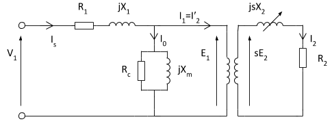
> In the equivalent circuit R1 represents, the resistance of the stator winding and X1 the stator leakage reactance.
> Magnetising reactance required to cross the air gap is represented by Xm and the core losses (hysteresis and eddy current) by Rc
> On the rotor side, the induced emf is affected by the slip. The rotor resistance and reactance are represented by R2 and X2, with X2 being dependant on the frequency of the inductor rotor emfs.
Simplified induction motor block
The Simplified Induction Motor block represents the electrical and torque characteristics of an induction motor powered by an ideal AC supply. The circuit can be simplified by eliminating the ideal transformer. The following figure shows the equivalent circuit model of the Simplified Induction Motor block.
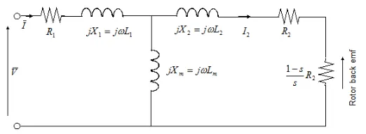
In the figure:
-
R1 is the stator resistance.
-
R2 is the rotor resistance with respect to the stator.
-
L1 is the stator inductance.
-
L2 is the rotor inductance with respect to the stator.
-
Lm is magnetizing inductance.
-
s is the rotor slip.
-
V and I are the sinusoidal supply voltage and current phasors.
> Rotor slip s is defined in terms of the mechanical rotational speed ωm, the number of pole pairs p, and the electrical supply frequency ω by
s=1−pωmω
This means that the slip is one when starting, and zero when running synchronously with the supply frequency.
> For an n-phase induction motor the torque-speed relationship is given by:
T=npR2sωVrms2(R1+R2+1−ssR2)2+(X1+X2)2
where:
-
Vrms is the line-neutral supply voltage for a star-configuration induction motor, and the line-to-line voltage for a delta-configuration induction motor.
-
n is the number of phases.
You can parameterize this block in terms of the preceding equivalent circuit model parameters or in terms of the motor ratings the block uses to derive these parameters.
This block produces a positive torque acting from the mechanical C to R ports.
Thermal ports
The block has two optional thermal ports, one per winding, hidden by default. To expose the thermal ports, right-click the block in your model, and then from the context menu select Simscape > Block choices > Show thermal port. This action displays the thermal ports on the block icon, and exposes the Temperature Dependence and Thermal Port parameters. Use the thermal ports to simulate the effects of copper resistance losses that convert electrical power to heat.
Limitations
> The block does not model the starting mechanism for a single-phase induction motor.
> When you parameterize the block by motor ratings, the block derives the equivalent circuit model parameters by assuming that the effect of the magnetizing inductance Lm is negligible, and the magnetizing inductance is not included in the simulated component.
To calculate the ratio of starting torque at half voltage & frequency to rated values
Given parameters:
> Number of phases (ph) - 3
> Frequency (Fz) - 50Hz
> X1 = X2 = 0.1 ohm
> R1 = R2 = 0.2 ohm
Ratio of starting torque at half voltage & frequency to rated values equals
`(T1)/(T2) = ((3*V^2*R2)/(Wms*((R1+R2)^2 + (X1+X2)^2)))/((3*(V/2)^2*R2)/(Wms*((R1+R2)^2 + (X1+X2)^2)))`
where, T1 = starting torque with half rated voltage and frequency
T2 = starting torque with rated voltage and frequency
V = Voltage
Wms = Synchronous speed
R1 = Stator resistance
R2 = Rotor resistance
X1 = Stator inductance
X2 = Rotor inductance
`Wms = (2*pi*120*Fz)/P`
where, Fz = frequency
P = number of poles
Starting torque at half voltage & frequency
For half rated voltage and frequency the values are divided by 2
`T1 = ((3*(V/2)^2*R2)/(Wms*((R1+R2)^2 + (X1+X2)^2)))`
`T1 = ((3*(V/2)^2*0.2)/(((2*pi*120*50)/(2*P))*((0.16 + 0.4))))`
`T1 = (3/75398.2)*P*V^2`
`T1 = 3.9788e^-5 *P*V^2`
Starting torque at rated voltage & frequency
`T2 = ((3*V^2*R2)/(Wms*((R1+R2)^2 + (X1+X2)^2)))`
`T2 = ((3*V^2*0.2)/(((2*pi*120*50)/P)*((0.16 + 0.4))))`
`T2 = (3/376991)*P*V^2`
`T2 = 7.9577e^-5 *P*V^2`
Ratio of starting torque at half voltage & frequency to rated values equals
`(T1)/(T2) = (3.9788e^-5 *P*V^2)/(7.9577e^-5 *P*V^2)`
`(T1)/(T2) = 0.5`
Make a MATLAB script file which will plot speed torque characteristics for frequency control method
A Matlab script is made as shown below to plot the speed torque characteristics
clear all
close all
clc

% Inputs

% Voltage per phase
V = 230/sqrt(3);
% Number of phase
ph = 3;
% Number of poles
P = 4;
% Stator resistance and inductance
R1 = 0.095;
X1 = 0.680;
% Rotor resistance and inductance
R2 = 0.23;
X2 = 0.672;
% Magnetizing inductance
Xm = 18.7;

% Calculate stator equivalent equations
Zeq = 1i*Xm*(R1+1i*X1)/(R1+1i*(X1+Xm));
Veq = abs(V*1i*Xm/(R1+1i*(X1+Xm)));

% Frequencies
Fz = linspace(10,50,10);

% Loop
for i=1:10
    % Motor Speed calculation
    w  = (4*3.14*Fz(i))/P;
    Ns = (120*Fz(i))/P;
    for n=1:100
        % Slip
        s(n) = n/100;
        % Motor speed in rpm
        W(n) = Ns*(1-s(n));
        % Current in rotor
        I2 = abs(Veq/(Zeq+1i*X2+R2/s(n)));
        % Torque calculation
        T(n) = ph*I2^2*R2/(s(n)*w);
    end

    % To display maximum speed of motor at different frequencies
    Curve=['The maximum speed of motor at ', num2str(Fz(i)),'Hz'];
    disp(Curve)
    disp(W(1))

    % Plot
    plot(W,T);
    hold on
    grid on
    axis ([0 1485 0 600])
    title('Speed torque characteristics for frequency controled induction motor');
    xlabel('Speed of motor in (rpm)');
    ylabel('Torque of motor in (N-m)');
end
legend('Fz=10.0Hz','Fz=14.4Hz','Fz=18.8Hz','Fz=23.3Hz','Fz=27.7Hz','Fz=32.2Hz','Fz=36.6Hz','Fz=41.1Hz','Fz=45.5Hz','Fz=50.0Hz');
Result
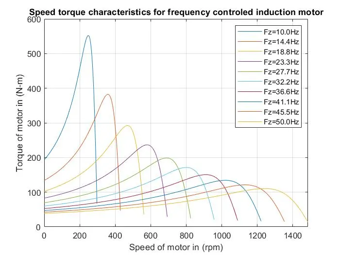
Plot of the speed torque curve by frequency control method
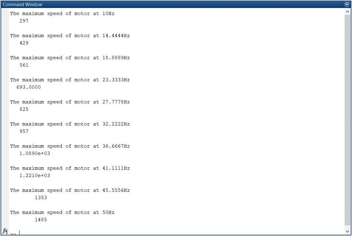
Maximum speed attained by motor at each frequencies
Conclusion
wkt, `(V/(Fz))prop phi`
> In which the frequency is varied and the voltage is made to be constant.
> Therefore from the plot it is seen that as the frequency increases the maximum torque reduces and the maximum speed increases respectively.
> The increasing maximum speed of the motor according to the frequencies is show in the command window
> If the voltage is also varied with the frequency as such, the flux is maintained a constant then the maximum torque will be constant untill the inverter short time limit.