Design concept of HEV Powertrain of towing truck for aircrafts in runways
Objective
> Weights considered in an aircraft
> Diffrence Between ground speed and air speed
> Definition of Taxiing
> Phases of flight from hanger to take off
> Calculation of power required to push or pull an aircraft using towing truck
> Calculation and block diagram of Powertrain
Total weight of various types of aircrafts.
Gross weight of aircrafts:
The aircraft gross weight (also known as the all-up weight and abbreviated AUW) is the total aircraft weight at any moment during the flight or ground operation.
An aircraft's gross weight will decrease during a flight due to fuel and oil consumption. An aircraft's gross weight may also vary during a flight due to payload dropping or in-flight refuelling.
At the moment of releasing its brakes, the gross weight of an aircraft is equal to its takeoff weight. During flight, an aircraft's gross weight is referred to as the en-route weight or in-flight weight.
Design weight limits:
An aircraft's gross weight is limited by several weight restrictions in order to avoid overloading its structure or to avoid unacceptable performance or handling qualities while in operation. The absolute maximum weight capabilities of a given aircraft are referred to as the structural weight limits.
The types of design weight limits considered are:
>Maximum design taxi weight (MDTW)
The maximum design taxi weight (also known as the maximum design ramp weight (MDRW)) is the maximum weight certificated for aircraft manoeuvring on the ground (taxiing or towing) as limited by aircraft strength and airworthiness requirements.
>Maximum design takeoff weight (MDTOW)
Is the maximum certificated design weight when the brakes are released for takeoff and is the greatest weight for which compliance with the relevant structural and engineering requirements has been demonstrated by the manufacturer.
>Maximum design landing weight (MDLW)
The maximum certificated design weight at which the aircraft meets the appropriate landing certification requirements. It generally depends on the landing gear strength or the landing impact loads on certain parts of the wing structure.
The MDLW must not exceed the MDTOW.
The maximum landing weight is typically designed for 10 feet per second (600 feet per minute) sink rate at touch down with no structural damage.
>Maximum design zero fuel weight (MDZFW)
The maximum certificated design weight of the aircraft less all usable fuel and other specified usable agents (engine injection fluid, and other consumable propulsion agents). It is the maximum weight permitted before usable fuel and other specified usable fluids are loaded in specified sections of the airplane. The MDZFW is limited by strength and airworthiness requirements. At this weight, the subsequent addition of fuel will not result in the aircraft design strength being exceeded. The weight difference between the MDTOW and the MDZFW may be utilised only for the addition of fuel.
>Minimum flight weight
Minimum certificated weight for flight as limited by aircraft strength and airworthiness requirements.
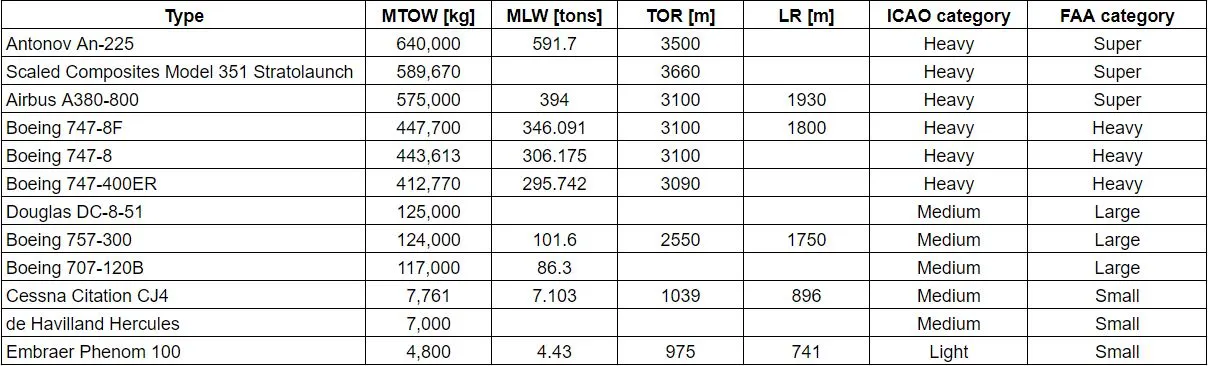
List of weight of some aircrafts
MTOW = Maximum take-off weight,
MLW = Maximum landing weight,
TOR = Take-off run,
LR = Landing run
Difference between ground speed and air speed
Wind speed
For a reference point picked on the ground, the air moves relative to the reference point at the wind speed. Notice that the wind speed is a vector quantity and has both a magnitude and a direction. Direction is important. A 20 mph wind from the west is different from a 20 mph wind from the east. The wind has components in all three primary directions (north-south, east-west, and up-down).
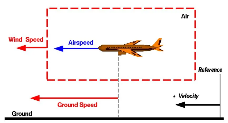
In this figure, we are considering only velocities along the aircraft's flight path. A positive velocity is defined to be in the direction of the aircraft's motion. We are neglecting cross winds, which occur perpendicular to the flight path but parallel to the ground, and updrafts and downdrafts, which occur perpendicular to the ground.
Ground speed
For a reference point picked on the ground, the aircraft moves relative to the reference point at the ground speed. Ground speed is also a vector quantity so a comparison of the ground speed to the wind speed must be done according to rules for vector comparisons.
Air speed
The important quantity in the generation of lift is the relative velocity between the object and the air, which is called the airspeed. Airspeed cannot be directly measured from a ground position, but must be computed from the ground speed and the wind speed. Airspeed is the vector difference between the ground speed and the wind speed.
Airspeed = Ground Speed - Wind Speed
On a perfectly still day, the airspeed is equal to the ground speed. But if the wind is blowing in the same direction that the aircraft is moving, the airspeed will be less than the ground speed.
Conclusion
> True airspeed is simply the speed at which an aircraft is moving relative to the air it is flying in. As such, it’s also the speed at which the air is flowing around the aircraft’s wings.
> Ground speed, on the other hand, is the aircraft’s speed relative to the ground.
> An aircraft climbing completely vertically would have a ground speed of zero.
> While airspeed is what determines whether there is enough airflow around an aircraft to make it fly, ground speed is what determines how fast an aircraft will get to its destination.
Using aircraft engine power to move it on the ground at Airport
Taxiing:
Taxiing (rarely spelled taxying) is the movement of an aircraft on the ground, under its own power, in contrast to towing or push-back where the aircraft is moved by a tug. The aircraft usually moves on wheels, but the term also includes aircraft with skis or floats (for water-based travel).
An airplane uses taxiways to taxi from one place on an airport to another; for example, when moving from a hangar to the runway. The term "taxiing" is not used for the accelerating run along a runway prior to takeoff, or the decelerating run immediately after landing, which are called the takeoff roll and landing rollout, respectively.
When taxiing, aircraft travel slowly. This ensures that they can be stopped quickly and do not risk wheel damage on larger aircraft if they accidentally turn off the paved surface. Taxi speeds are typically 30 to 35 km/h
Taxiing is not recomended because:
The engine of aircraft produces high power during taxiing. This may cause other support machines or vehicles such as maintenance stand, dollies, chocks, refuelers etc to be blow away which may possibly make higher damage in the surrounding area, though the taxiway is away from the hangers.
An example of such insident is, while taxiing for takeoff, an airplane reportedly made a sharp right turn onto a taxiway. Blast from engines no. 3 and no. 4 blew a maintenance stand into engine no. 2 of another airplane. The stand impacted the engine fan cowl, resulting in a 6- by 1-in (15.2- by 2.5-cm) puncture. In addition, the engine no. 1 cowl was laying under the engine and was blown across the ramp, causing damage to the latching mechanism.
Phases of flight from hanger to take off
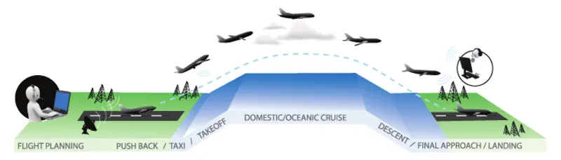
The different phases of a flight is shown in the figure below
> The aircraft is serviced and fuelled at first for the departure
> Then after the passangers are abord the apron handler removes the chocks.
> Pushback is an airport procedure during which an aircraft is pushed backwards away from an airport gate by external power. Pushbacks are carried out by special, low-profile vehicles called pushback tractors or tugs.
> Although many aircraft are capable of moving themselves backwards on the ground using reverse thrust (a procedure referred to as a powerback), the resulting jet blast or prop wash might cause damage to the terminal building or equipment.
> Engines close to the ground may also blow sand and debris forward and then suck them into the engine, causing damage to the engine. A pushback is therefore the preferred method to move the aircraft away from the gate.
> Closer to departure, an aircraft tug will park right in front of the nose wheel. The tug might be directly attached to the plane's nose gear with a tow bar, or could be a "wheel-lift" tug.
> These tugs cradle the nose gear, then lift it up before moving the plane. That gives the tug driver control over the plane's direction during pushback.
> The aircrafts always moves on the ground following the yellow lines, to avoid any collision with the surrounding buildings, vehicles or other aircrafts.
> The taxiing motion has a speed limit. Before making a turn, the pilot reduces the speed further to prevent tire skids.
> The aircrafts that are landing or taking off have higher priority. The other aircrafts have to wait for these aircrafts before they start or continue taxiing.
> Takeoff is the phase of flight in which an aircraft goes through a transition from moving along the ground (taxiing) to flying in the air, usually starting on a runway. Usually the engines are run at full power during takeoff.
> Following the taxi motion, the aircraft stops at the starting line of the runway. Before takeoff, the engines, particularly piston engines, are routinely run up at high power to check for engine-related problems. This makes a consid- erable noise.
> When the pilot releases the brakes, the aircraft starts accelerating rapidly until the necessary speed for take-off is achieved.
Take off power, tyre design, rolling resistance, tyre pressure, brake forces when landing.
Take off power
On take-off, in order to position the aircraft to a safe height away from terrain and obstacles (i.e. a flight path of maximum height and minimum ground distance desired), the engine thrust is set to a high ‘take-off power’ setting (although this is not necessarily full power) and the aircraft attitude is pitched up to maintain a specific speed (usually in the region of V2 + 15kts).
The takeoff speed required varies with air den- sity, aircraft weight, and aircraft configuration (flap and/or slat position, as applicable). Air density is affected by factors such as field ele- vation and air temperature.
Tyre design
Designing aircraft tyres requires sizing, weight requirement, regulatory requirements including foreign regulation in many cases etc. Two types of tires are used in aircraft applications — bias-ply tires and radial tires. Although both types of tires share some similarities in design, there are some differences.
> Bias-ply tire
The bias ply tyre (illustrated) consists of casing plies running diagonally at approximate right angles to one another. The number of plies and the angles at which they are laid dictate strength and load capacity.
High-performance bias aircraft tyres feature inter-tread reinforcing fabric (ITF). This provides additional high-speed stability, reduces tread distortion under load, protects the casing plies from damage and can act as wear indicators on retreadable tyres.
Some bias tyres, such as Dunlop's tires for the A400M, feature a kevlar like material to provide for even higher strength.
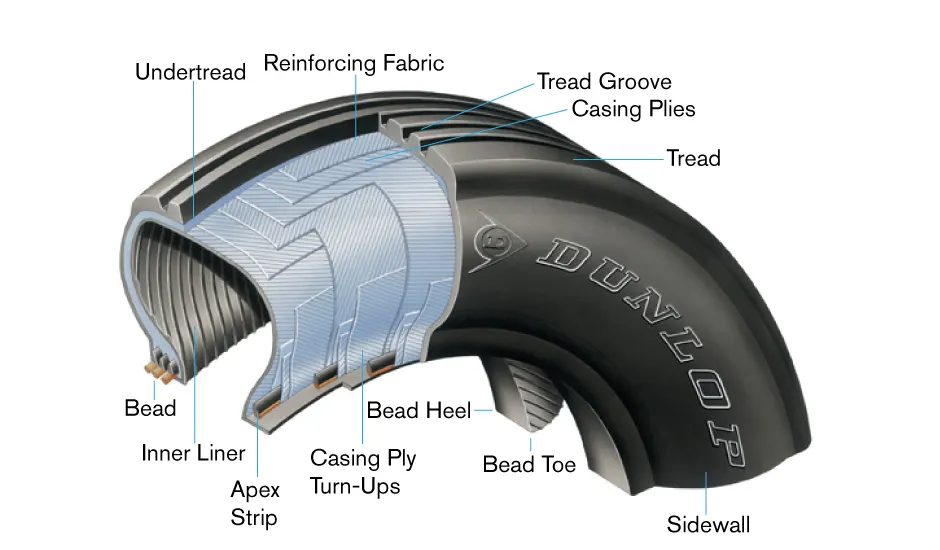
A cutaway of a typical bias-ply tire is shown in the above figure. Bias-ply tires are popular choices for aircraft tires because of their durability and retreadability. The tire construction consists of the following components:
Tread: The tread is made of rubber mixed with other additives to obtain the desired level of toughness, durability, and resistance to wear. The tread pattern is designed to aircraft operational requirements, with the ribbed tread design used widely due to its good traction under varying runway conditions.
Sidewall: The sidewall is a protective layer of rubber that covers the outer casing ply. It extends from the tread edge to the bead area.
Tread Reinforcing fabric: One or more layers of fabric that strengthens and stabilizes the tread area for high-speed operation. It also serves as a reference for the buffing process when tires are retreaded.
Casing Plies: Alternate layers of rubber-coated fabric (running at opposite angles to one another) provide the strength of the tire.
Beads: Hoops of high tensile strength steel wire that anchor the casing plies and provide a firm mounting surface on the wheel. The outer edge of the bead that fits against the wheel flange is called the bead heel. The inner bead edge is called the bead toe.
Apex Strip: A wedge of rubber affixed to the top of the bead bundle.
Casing Ply Turnups: The casing plies are anchored by wrapping them around the wire beads, thus forming the ply turnups.
Chafer: A protective layer of rubber and/or fabric located between the casing plies and wheel to minimize chafing.
Inner liner: In tubeless tires, the liner is a layer of low permeability rubber that acts as a built-in tube and restricts gas from diffusing into the casing plies. In tube-type tires, a thinner liner is used to prevent tube chafing against the inside ply.
Undertread: Undertread are reinforcing plies of rubber-coated fabric placed under the buff line cushion to protect casing plies and strengthen and stabilize the tread area. They are considered an integral part of the casing construction.
Undertread: Undertread are reinforcing plies of rubber-coated fabric placed under the buff line cushion to protect casing plies and strengthen and stabilize the tread area. They are considered an integral part of the casing construction.
>Radial-ply tire
Radial tires are the most modern design of aircraft tyres. It is a design that is similar to that of car tyres. Typically, the radial tyre offers more landings per tread and lighter weight than a bias tyre; though sometimes at the expense of retread lives.
Radial aircraft tyres differ to bias aircraft tyres in that the plies all run radially from bead to bead at approximately 90° to the centre-line of the tyre. Angled belt plies are laid between the tread and the top casing ply, resulting in a flatter tread and adding strength to the tyre.
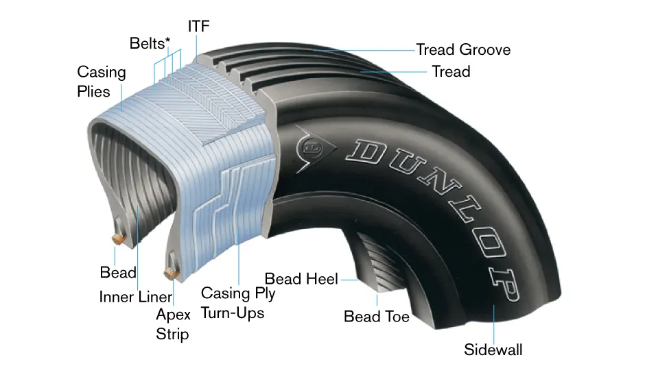
A typical radial tire is illustrated in the above figure. With their rigid belt, they provide increased landings and reduced rolling resistance. They have fewer components in their construction and are lighter than similarly sized bias ply tires. Components that differ from bias-ply construction as follows
Inter tread reinforcing fabric: A layer of reinforcing rubber coated fabric placed on top of the belts to aid in high speed operation.
Belts: A composite structure that stiffens the tread area for increased landings. The belt plies increase the tire strength in the tread area.
Casing Plies: As in bias-ply tires, the casing plies are layers of rubber-coated fabric. However, unlike those in bias plies that run at opposite angles to one another, radial plies run radially from bead to bead.
Chippers: The chippers are layers of rubber-coated fabric applied at diagonal angles that improve the durability of the tire in the bead area.
Rolling resistance
Rolling resistance, sometimes called rolling friction or rolling drag, is the force resisting the motion when a body (such as a ball, tire, or wheel) rolls on a surface. The cause of rolling resistance lies in the slippage between the wheel and the surface, which dissipates energy.
Rolling resistance can be given by the below fomula
`Frr = mur *m*g`
Where, `Frr`= Rolling resistance force
`mur` = Rolling resistance coefficient
`m` = Mass in Kg
`g` = Gravitational force
Tyre pressure
Aircraft tires generally operate at high pressures, up to 200 psi (14 bar; 1,400 kPa) for airliners, and even higher for business jets. Tests of airliner aircraft tires have shown that they are able to sustain pressures of maximum 800 psi (55 bar; 5,500 kPa) before bursting.
Aircraft tires are usually inflated with nitrogen to minimize expansion and contraction from extreme changes in ambient temperature and pressure experienced during flight. Dry nitrogen expands at the same rate as other dry atmospheric gases (normal air is about 80% nitrogen), but common compressed air sources may contain moisture, which increases the expansion rate with temperature. The use of an inert gas for tire inflation will eliminate the possibility of a tire explosion.
Brake force when landing
Hydraulic braking
The brake units are powered by the hydraulics system. An electrical signal is sent from the flight deck to hydraulic actuators near the main landing gear. Here, hydraulic fluid at 3,000 pound per square inch is used to force the brake unit against the wheel, thus slowing it down.
This system works fine, but the pipes and actuators that form this part of the hydraulic system come at a considerable weight cost. Extra weight leads to more fuel burn, which in turn increases costs and carbon emissions.
Electrical braking
To reduce the weight of the braking system electricity is used to power the braking system. When the pilots press on the brake pedals, an electrical signal is sent to the brake unit on the wheel. Here, electrically powered actuators are used to press the carbon brake disc against the wheel, slowing it down.
By changing to electric brakes, a 787 Dreamliner-8 saves 141 pounds per aircraft and a 787 Dreamliner-9 saves 245 pounds. The brakes are also known as “plug and play” because electrical wiring replaces the traditional hydraulics and it’s much easier and quicker to change the brake units when needed. Smart features also allow engineers to monitor the brake performance more closely, giving a real-time measurement of wear on the carbon disks.
To calculate the force and power required to push / pull an aircraft by a towing vehicle.
Assumptions made:
> Aircraft - Boeing 747-8F
> Weight of the aircraft - 447.7 Tonnes
> Weight of the towing vehicle - 20 Tonnes
> Coefficient of rolling resistance of the aircraft - 0.005
> Coefficient of rolling resistance of the towing vehicle - 0.002
> Velocity of towing - 15kmph/4.1mps
> Density of air - 1.225
> Coefficient of drag of aircraft - 0.02
> Coefficient of drag of towing truck - 0.02
> Frontal area of aircraft - 380 m^2
> Frontal area of towing truck - 40 m^2
The power requirment calculation is made using Excel calculator
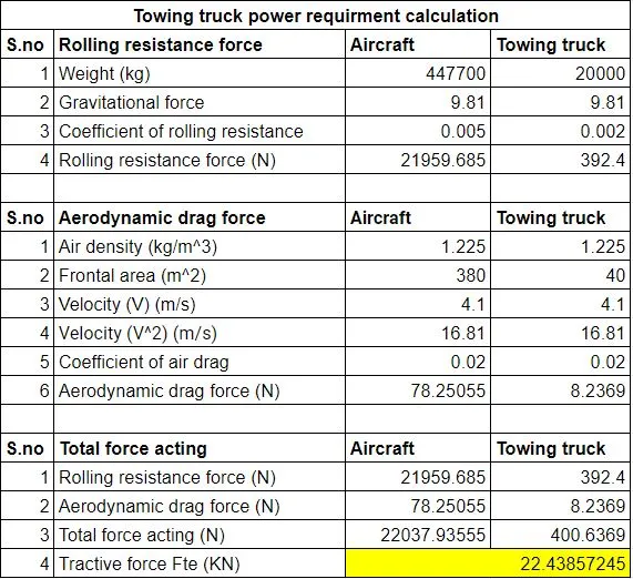
The link for excel sheet is given below
(https://docs.google.com/spreadsheets/d/1tA2mxwMNyFOEyyjftHSsg2H_bVFd7oQvIqO0Ogc37_4/edit?usp=sharing)
The tractive force required is
Fte = 22.43KN
Power is evaluated from the total force at a given speed
Therefore, if the aircraft is to be moved at 15kmph/4.1mps then,
Power (P) = 22.43 * 4.1 = 91.96 KW
P = 91.96 KW
To design an electric powertrain with type of motor, it’s power rating, and energy requirement to fulfill aircraft towing application.
Torque calculation
Since the total tractive force (Fte) is known the torque (T) can be calculated using the below equation,
`T = ((Fte*r)/(G*eta))`
where, `T` = Torque in N-m
`Fte` = Total tractive force in N
`G` = Gear ratio
`eta` = Gear efficiency
Consider,
The radius of the tyre of towing truck = 0.5m
Gear ratio = 11
efficiency = 0.95
Then, `T = ((22.43*0.5)/(11*0.95))`
`T = 1073.2 Nm`
Selection of motor
Selection of motor is done based on the derived power and torque values.
A TEFC (Totally enclosed fan colled) class F motor is selected with the following specifications
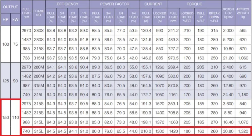
There are three standards of efficiency in motors. They are
IE1 - Standard efficiency motor
IE2 - High efficiency motor
IE3 - Premium efficiency motor
The motor which I selected comes under the IE2 standard. Therefore the motor has high efficiency(`eta`) of 94.5 during full load with power output of 110 KW and full load torque of 1420 N-m.
The rated voltage of the motor - 400V
The rated current of the motor at full load - 210A
Calculating output power from power converter
To get the maximum required output from the motor the losses in the motor is compensated by the input power of the motor. Therefore the input power of the motor can be calculated by the following equation.
Efficiency of the selected motor during full load will be `eta = 0.945`
`P_i = (P_o/eta)`
`P_i = 91.96/0.945`
`P_i = 97.31 KW`
Therefore the power output from the power converter will be 97.31 KW
Calculating battery voltage output
The battery output voltage = Power converter output voltage (when `delta = 1`)
WKT,
`P = V*I`
where, `P` = Power in W`
`V` = Voltage in V
`I` = Current in A
therefore, `V_b= P_i/I_i`
`V_b = 97310/210`
`V_b = 463.38 V`
The battery voltage output given to the power converter will be 463.38 V
Selection of battery
wkt,
`E = P*t`
where, `E` = Energy
`P` = Power in KW
`t` = Average time required for towing the aircraft from gate to taxiway
Assuming the time required for towing the aircrft from gate to taxiway to be 10 minutes
Since the voltage provided by the battery will be 463.38 V, power of the battery will be
`P_b = V_b*I_b`
`P_b = 463.38 xx 210`
`P_b = 97.3 KW`
Therefore, `E = 97.3 xx 600`
`E = 58380 KJ`
`E = 16.21 KWh`
A 16.21 KWh battery is required to push or pull the aircraft for 10 minutes
Duty cycle of the power converter
If input current is maintained equal to the output current then,
`(P_o/V_o) = (P_b/V_b)`
`(P_o/P_i) = (V_o/V_i)`
`delta = (V_o/V_i)`
where, `delta` = duty cycle
`delta = 91.96/97.3`
`delta = 0.945`
Which is equivalent to the efficiency of the motor
Therefore the duty cycle ranges from `delta = 0 - 0.945`
Then, with the battery voltage input as 463.38, the output voltage from the power converter varies from 0V - 437V
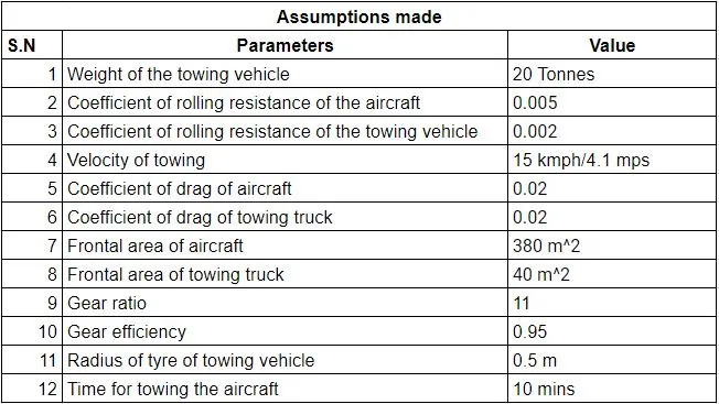
Required assumptions
The assumptions made to design the electric powertrain are as given below
Block diagram of the powertrain
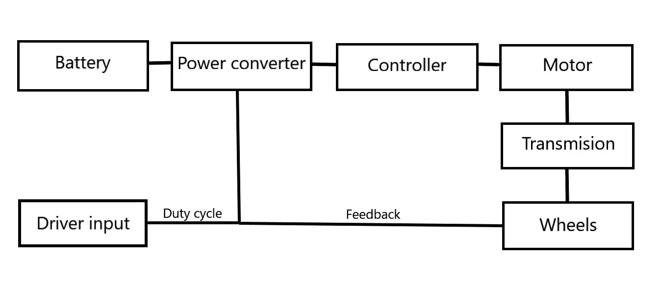
The block diagram is drawn as shown below.