Sketch a G+1 residential plan according to Vaastu Shastra and Calculation of Loads as per IS code
PROJECT 2 :
Sketch a G+1 floor residential plan, according to Vaastu Shastra, and list down the names of the structural drawings required to be provided to the site for construction.
Also, assume the sizes of the structural elements (Column, Beam, Slab, etc.,) and accordingly calculate the individual corresponding loads from the members as per IS code.
AIM:
To Draw a G+1 floor residential plan, according to Vaastu Shastra, and list down the names of the structural drawings required to be provided to the site for construction also, to assume the sizes of the structural elements (Column, Beam, Slab, etc.,) and accordingly calculate the individual corresponding loads from the members as per IS code.
Introduction:
- Vastu Shastra is an ancient Indian science that capitalizes on the concept of prosperity. It links a person’s health and happiness directly with the layouts and construction of a building.
- Vastu is a science that helps civil engineers figure out where and what kind of room should go in a building. It works well with nature. It mostly depends on how much light and air there is.
- The north point is the first point of reference for Vastu.
- To calculate various types of loads from the members as per the following IS Codes.
1. IS 456-2000, revised for reinforced concrete structure
2. IS 875-1987, revised 2018 ( PART 1) for Dead load
3. IS 875-1987 revised 2008 ( PART 2 ) for live load
4. IS 875-1987 revised 2015 ( PART 3 ) for wind load
Procedure:
G+1 floor residential plan according to Vaastu Shastra:
Basic principles:
- shape: Rooms should be perfect and preferably square or rectangular.
- Room basics: The room should be airy, well-lightened, bright and clean.
- Home basics: Centre of the house should be an empty space
- Stairs and furniture: Heavy furniture should be kept in the south direction.
- Water: Avoid plants and water features in the bedroom.
- Mirror placement: Mirror facing the bed is strictly not allowed. mirrors in the bedroom should be placed such as way that the bed cannot be seen.
Auspicious direction as per Vaastu Shastra :
- kitchen: SOUTH-EAST is best, NORTH-EAST to be avoided.
- staircase: SOUTH-WEST is best, NORTH-EAST is avoided.
- Toilet: NORTH-WEST is best, NORTH-EAST to be avoided.
- master bedroom: SOUT-WEST is best.
- Guest room: NORTHWEST is best,
- Living room: NORTH-EST is best,
- Overhead Overhead: WEST is best.
- Underground tank: NORTH-EAST is best, SOUTH-WEST is to be avoided.
Diagram:
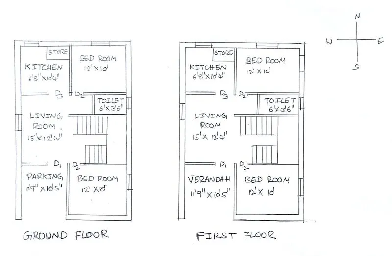
Ground floor dimensions:
Living Room = 15' x 12'4"
Bedrooms = 12' x 10'
Kitchen = 6'8" x 10'4''
Toilet = 6' x 3'6''
Parking = 11'9'' x 10'5''
First floor dimensions:
Living Room = 15' x 12'4"
Bedrooms = 12' x 10'
Kitchen = 6'8" x 10'4''
Toilet = 6' x 3'6''
The names of the structural drawings required to be provided to the site for construction:
- For any construction project, construction documents, drawings, sketches, and plans are needed for the proper execution of the project. Following are the types of drawings in a typical set of construction documents:
1. Architectural drawings:
- Setting out a plan
- Floor plans
- Elevation drawings
- Section drawings
- Working drawings
- Opening drawings
- Rood drainage plan
- Flooring plan
- Furniture plan
- Typical details
2. Electrical drawings :
- Electrical legend
- Floor lighting plan
- Floor power plan
- Single-line diagram
- Fire alarm layout
- Floor sound system and CCTV camera
- Equivalency chart
- Lightening protection earthing details
3.Plumbing drawings/Public health drawings:
- Legend and general notes
- Sewerage and rainwater layout plan
- Manhole schedule
- Plumbing construction details
- Water supply layout
4. Structural drawings:
- General notes
- Typical sections
- Foundation excavation
- Footing sections
- Ground floor column plan
- Column sections
- Ground floor beams plan
- Beam sections
- Ground floor slab bottom rebar detail
- Ground floor slab top rebar detail
- Ground floor slab section
- Overhead water tank design
- Septic tank design
5. Fire Fighting drawings:
- Legend and notes
- Fire fighting layout plan(for each floor)
6. HVAC drawings:
- Legend and general notes
- AC Layout plan(for each floor)
- Equipment schedule and installation detail
Let us assume the sizes of the structural elements (Column, Beam, Slab, etc.,) and accordingly calculate the individual corresponding loads from the members as per IS code.
All columns are 300mm x 300mm
All beams are 300mm x 450mm
The slab thickness is 125mm
The height of the wall is 4.5m
DEAD LOAD CALCULATIONS:
1. Columns:
All sizes of columns: 300 mm x 300 mm
Length of the column:0.3m
width of the column:0.3m
Height of the column:4.5m= Height of the wall
Dead load =?
Formula:
Dead load = unit weight of the column x volume of the column
Unit weight of the RCC column = 25 KN/m^3
The volume of the column = 0.3 x 0.3x 4.5 = 0.405 m^3
Dead load = 25 x 0.405 = 10.125 KN(point load)
A dead load of all columns of size (0.3mx0.3mx4.5m)= 10.125 KN.
2. Beams:
Size of the Beam = 300 mm x 450 mm
Width of the beam = 300 mm = 0.3 m
Length of the beam = 450 mm = 0.45 m
Unit weight of RCC beam = 25 KN/m^3
Formula: Dead load = unit weight x volume
Dead load or self-weight = 25 x 0.3 x 0.45 =3.375 KN/m.(UDL loading)
A dead load of all beams of size (0.3mx0.45m)= 3.375 KN/m.
3. Walls:
Height of a wall = 4.5 m.
The thickness of a Exterwall = 230 mm = 0.230 m
The thickness of a Internal wall = 150 mm =0.15 m
Dead load =?
Formula:
Wall load or Dead load = unit weight of the wall (Brick masonry) x volume of the wall
Unit weight of the brick masonry wall = 20 KN/m^2
- i) The volume of the External wall = 0.230 x 4.5 = 1.035 m^3
Dead load at External wall = 20 x 1.035 = 20.7 KN/m.(UDL loading)
External wall load on a beam of height 4.5m = 20.7 KN/m.
- ii) The volume of the Internal wall = 0.15 x 4.5 = 0.675 m^3
Dead load at internal wall = 20 x 0.675 = 13.5 KN/m.(UDL loading)
Internal wall load on a beam of height 4.5m = 13.5 KN/m.
4. Slabs:
The thickness of the slab: 125 mm or 0.125 m
Self-weight or Dead load =?
Formula:
Dead load or self-weight of the slab = unit weight of the slab x volume of the slab
Unit weight of the RCC slab = 25 KN/m^2
Dead load or self-weight = 25 x 0.125 = 3.125 KN/m2.(Area loading)
A dead load or self-weight of a slab of 125 mm thickness = 3.125 KN/m2.
5. Self-weight of the ceiling: 0.25 KN/m2 ( As per IS 875 Part 1 )
6. Self-weight of roofing: 0.83 KN/m2 ( As per IS 875 Part 1 )
7. Floor Finish: 1 KN/m2
LIVE LOAD CALCULATIONS:
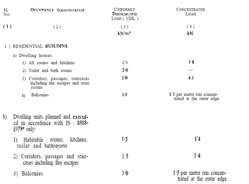
As per IS 875:1987 PART 2, Table number 1,
|
SL NO |
OCCUPANCY CLASSIFICATION |
UDL(KN/m2) |
POINT LOAD(KN) |
|
1 |
All rooms and kitchen |
2 |
1.8 |
|
2 |
Toilet and bathrooms |
2 |
- |
|
3 |
Store room and Terrace |
3 |
4.5 |
Reference:
WIND LOAD CALCULATION:
The wind load calculation is only considered for the height of the building being more than 10 m, So wind load calculation could be ignored for this type of residential building.
RESULTS:
i) The plan is prepared by the G+1 floor residential plan according to Vaastu Shastra.
ii) The names of the structural drawings required to be provided to the site for construction.
iii) Calculate the individual corresponding loads from the members as per IS code.