Creating Kitchen layout, Hatching of Architectural elements and sectional view of an Industrial Building in AutoCad
CHALLENGE 10:
Creating Kitchen layout, Hatching of Architectural elements, and sectional view of an Industrial Building in AutoCad.
AIM:
To create a Kitchen layout, Hatching of Architectural elements, and sectional view of an Industrial Building in AutoCad.
INTRODUCTION:
To Create a Kitchen layout, Hatching of Architectural elements, and sectional view of an Industrial Building in AutoCad. Create the Plan and Sections as shown in the Figures. Use proper dimension techniques and dimension styles to document the project. Assume the sizes of the doors and windows as per construction standards. Refer to sections for stair details if required. The tools are XL LINE horizontal and vertical, Draw tools, modify commands, to identify the objects layer properties are used. Mainly focus on tools in floor plan, kitchen layout, and column details are offsetting, rotating, scaling, filleting, and chamfering the sketched objects. annotations and dimensioning are mostly involved in structural drawings.
QUESTION-1:
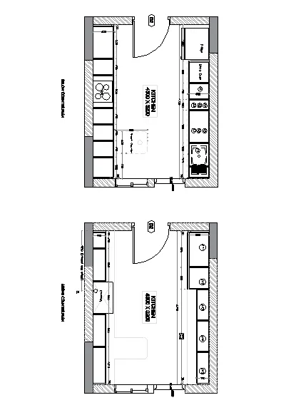
Create the layouts of the Kitchen and provide a hatches pattern as shown. Also, use blocks wherever required. Provide appropriate dimensions in the plan. Assume the size of doors, appliances and others as per the standards.
PROCEDURE:
- Open AutoCAD software and open a new drawing.
- Set the necessary limits and units.
- Type the REC command window and press enter

- Specify the first point: Type (0,0) at the command prompt and press enter(starting point)
- Specify the Next point: Type (@4300,3200) at the command prompt and press enter
- Type the O command window and press enter to draw the 230mm external wall.
- For the window take the size of the windows and make the offset from the external line the wall and trim the extra lines
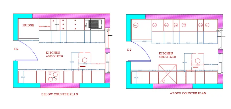
- Now take the line command to check the dimensions from the reference drawing and draw the given materials or kitchen utility
- Take the offset command for offsetting the lines use the “tr command for trimming lines
- For the creation of doted line go to the properties option change the line type select the line is discontinued lines
- Next to the property of lines change the size of the transparency.
- Layers can be done for each object of this kitchen layout.
- Hatches and door is provided as per dimensions.
- Provide all dimensions.
- After that draw an above counter plan with a reference to the below counter plan.
- Then provided Text and dimensions.
RESULT:
QUESTION-2:
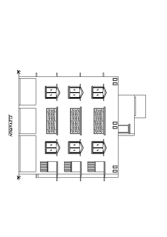
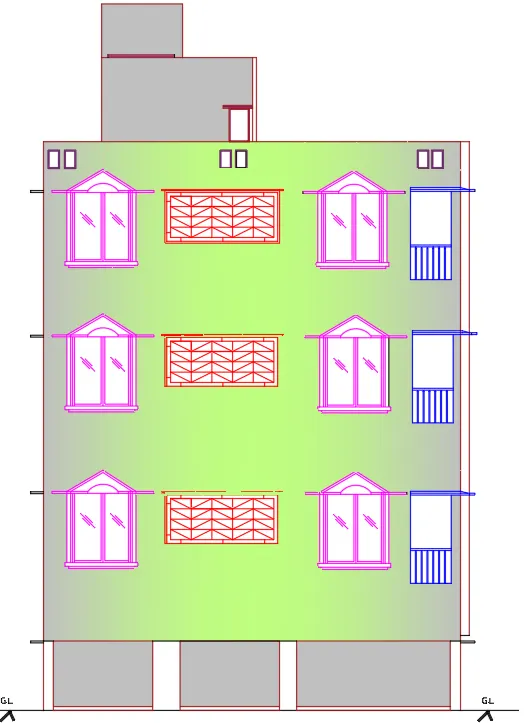
Create the elevation of the plan created in Challenge 7 and apply proper hatch in the walls, doors, windows, and other architectural elements. Refer to the dimensions in Plans and sections in Challenge 7.
PROCEDURE:
- Open AutoCAD software and open a new drawing.
- Set the necessary limits and units.
- Type the REC command window and press enter
- Specify the first point: Type (0,0) at the command prompt and press enter(starting point)
- For the elevation of the residential building, first, we draw the horizontal line using the line command with a length of 11574mm. Next, we need to draw another line from the previous line vertically with a length of 1200mm and create a rectangle.
- Next create a window as per construction standards and copy it to all 3 floors of elevation. Similarly, we create all elements in the elevation and inserted them properly.
- Door is created at the top building shown in the elevation.
- As per elevation we required hatching techniques are used.
- We have to provide a proper hatch-like pattern and solid in the hatch creation layout.
- Finally we provide hatching in the elevation diagram.
RESULT:
QUESTION-3:
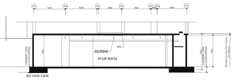
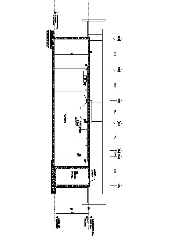
Create the section view of an industrial building as shown in Figure. Provide appropriate hatches and dimensions wherever required. Also, provide annotations to the drawing.
PROCEDURE:
- Open AutoCAD software and open a new drawing.
- Set the necessary limits and units.
- Type the REC command window and press enter
- Specify the first point: Type (0,0) at the command prompt and press enter(starting point)
- First draw the X-line at any point on the screen.
- Next offset the line to the top to a distance of 5850mm and we have to offset of last offset line to the distance of 300mm to the top
- Next draw the vertical X-line on any point on the horizontal line.
- Next offset of line to the right to a distance of 10635mm Next offset the last line with a distance of 3900mm to the right
- Next offset the 1st line with the distance of 5740mm to the right side.
- Next offset for the last line with the distance of 5025 to the right side.
- Offset the left and right edges with a distance of 500mm.
- Next trim the outer edges using the trim command.
- Next offset the bottom edge of the top floor to a distance of 30mm.
- Next offset the last line with a distance of 70mm to the bottom.
- Next offset the last line with a distance of 100mm to the bottom.
- Next draw the sprinkler pipe along with the duct pipe.
- The duct pipe thickness is 300mm and the thickness of the sprinkler pipe is 100mm.
- Next draw the manhole cover with a thickness of 750mm at the right top edge of the filter feed walls as shown in the figure
- Next draw the thickness of the pump room slab with the different layers using the line command.
- Next draw the circle with a radius of 500mm, and enter the text in the circle as given in the figure.
- Next use the single text command to enter the text where ever required in the section view of the industrial drawing.
- Finally use the hatch command to hatch the walls and floor slabs as drawn in the below figure.
- Finally use the Dimlinear command to put the dimensions wherever required in the drawing.
RESULT: