Creating Bar Bending schedule, Different Door types, and Creation of standard drawing templates using AutoCad
CHALLENGE 9:
Creating Bar Bending schedules, Different Door types, and Creation standard drawing templates using AutoCad
AIM:
To Creating Bar Bending schedule, Different Door types, and Creation of standard drawing templates using AutoCad
INTRODUCTION:
To create a Bar Bending schedule, Different Door types, and Creation standard drawing templates using AutoCad Use proper dimension techniques and dimension styles to document the project. Assume the sizes of the doors and windows as per construction standards. Annotations and dimensioning are mostly used in structural drawings.
QUESTION-1:
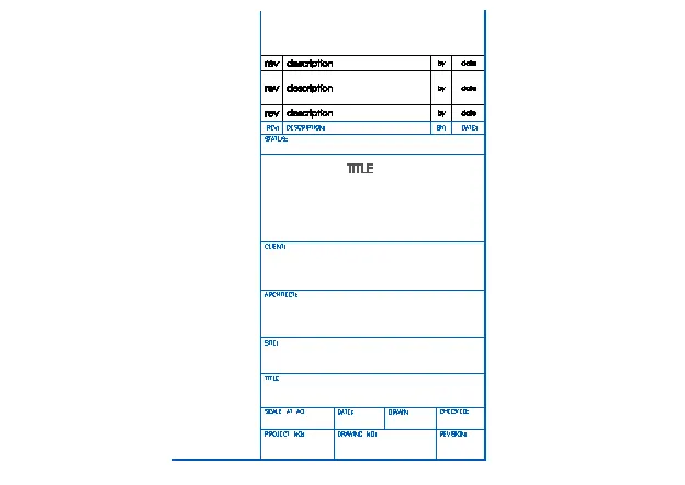
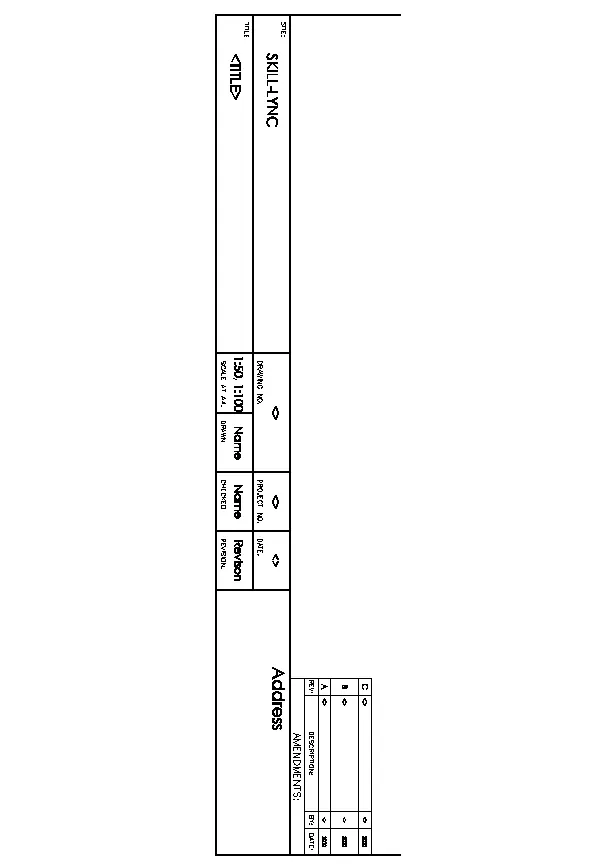
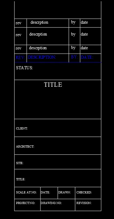
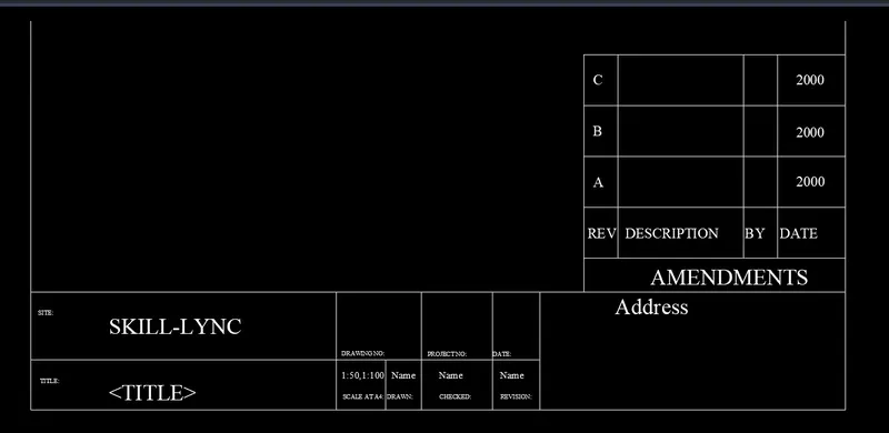
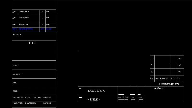
Create the templates as shown in the Figures. Take the title block size as per industry standards or you can assume it as per the size of the paper. Use text and attributes wherever required. After creating the title block you need to save it as a block with the names: Custom1_titleblock and Custom2_titleblock, respectively.
PROCEDURE:
- Open AutoCAD software and open a new drawing.
- Set the necessary limits and units.
- Type the REC command window and press enter

- Specify the first point: Type (0,0) at the command prompt and press enter(starting point)
- Draw the rectangular plot size 500 mm x 1200 mm by using the rectangular command.
- Explode the rectangle by using EXPLODE command and offsetting the line by using the offset command.
- To draw the table as per construction sizes and extra lines are trimmed.
- After each row and column provide the annotation using single-line text and a height is 200mm.
- After that the table is converted into a block by using the B command.
- First name the title Custom1_block and then selected the object and pick a point then enter it as a block.
11. Similarly we draw another table as per the assumed sizes of rectangles 1200 x 500,then off-setting lines as per the required table.
12. After that provide annotation and the text height is 15 mm to 20 mm.
13. After that the table is converted into a block by using the B command.
14. First name the title Custom1_block and then selected the object and pick a point then enter it as a block.
RESULTS:
QUESTION-2:
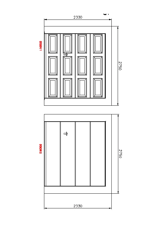
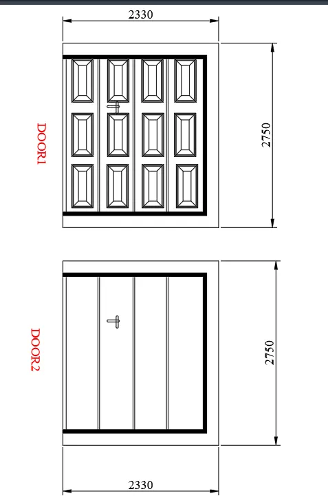
Create the door type for the warehouse as shown in the Figure. You need to create each door type as per standard size or given dimensions. Create the blocks of this door type after creating them.
PROCEDURE:
- Open AutoCAD software and open a new drawing.
- Set the necessary limits and units.
- Type the REC command window and press enter
- Specify the first point: Type (0,0) at the command prompt and press enter(starting point)
- Draw the rectangular plot size 2330 x 2750 mm by using the rectangular command.
- Explode the rectangle by using EXPLODE command and offsetting the line by using the offset command.
- After that create panels by an equal distance.
- And then to create Door panels as per construction sizes then copied to the required positions.
- Hatching is done to the internal and external walls.
- After that the table is converted into a block by using the B command.
- First name the title Custom_Door 1 &Custom_Door 2 and then selected the object and pick a point then enter it as a block.
- To provide Door 1 and Door 2 text with the color red with a rotation angle of 90.
RESULT:
QUESTION-3:
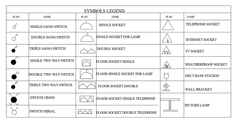
Create each symbol as a block with the name given in the legend. After creating the blocks arrange them in the legend as shown in the Figure.
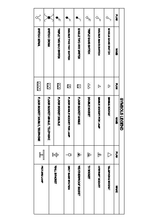
PROCEDURE:
- Open AutoCAD software and open a new drawing.
- Set the necessary limits and units.
- Type the REC command window and press enter
- Specify the first point: Type (0,0) at the command prompt and press enter(starting point)
- To draw the table as per the required sizes for electrical legends.
- To draw each legend and converted it to the block and inserted it into the required table.
- To create effective blocks for legends.
- After that go to the insert option and click on the field options and select the block name then inserted it into the table. The above procedure is the same for all legends.
- Final electrical legends as shown in the result.
RESULT:
QUESTION-4:
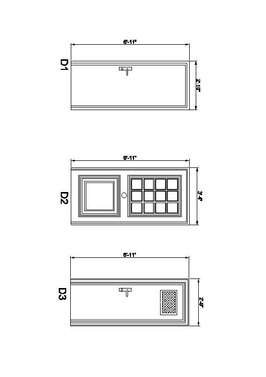
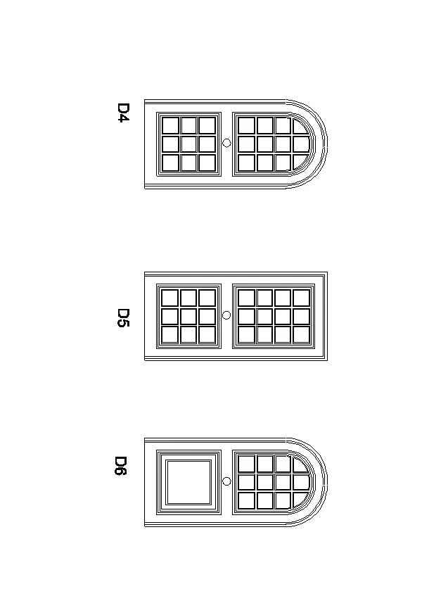
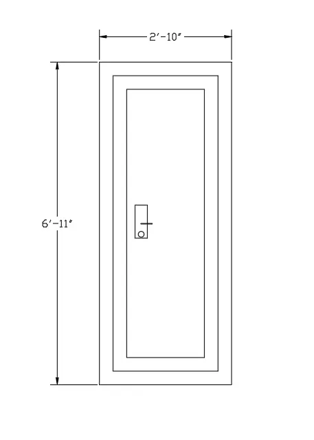
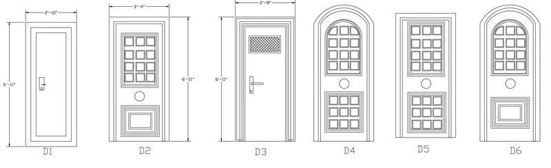
Create the door type for a residential building as a block. Save the name of the blocks as type. Use given dimensions or assume dimensions as per industry standards.
PROCEDURE:
DOOR-1:
- Open AutoCAD software and open a new drawing.
- Set the necessary limits and units.
- Type the REC command window and press enter
- Specify the first point: Type (0,0) at the command prompt and press enter(starting point)
- Draw the rectangle at a point@2'10",6'11"
- To take 3" offsetting each panel in the door.
- To create one locker to the door and inserted it.
- To draw the door name it Custom_door and converted it to the block.
- Provide the dimensions.
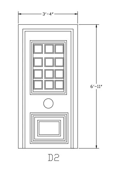
DOOR 2:
- Open AutoCAD software and open a new drawing.
- Set the necessary limits and units.
- Type the REC command window and press enter
- Specify the first point: Type (0,0) at the command prompt and press enter(starting point)
- Draw the rectangle at a point@3'-4",6'-11"
- To take 3" offsetting each panel in the door.
- To draw the door name it Custom_door2 and converted it to the block.
- Provide the dimensions.
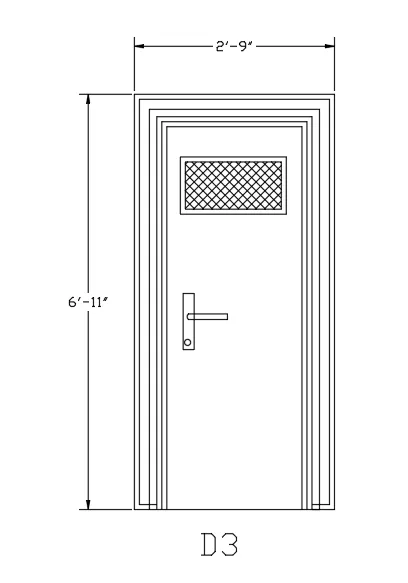
DOOR 3:
- Open AutoCAD software and open a new drawing.
- Set the necessary limits and units.
- Type the REC command window and press enter
- Specify the first point: Type (0,0) at the command prompt and press enter(starting point)
- Draw the rectangle at a point@2'9",6'11"
- To take 3" offsetting each panel in the door.
- To create one locker to the door and inserted it.
- Hatch pattern is used in the door.
- To draw the door e it Custom_door3 and converted it to the block.
- Provide the dimensions.
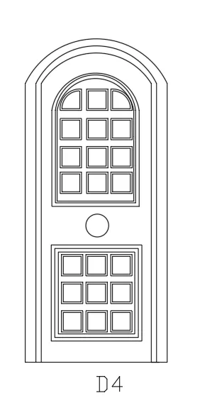
DOOR 4:
- Open AutoCAD software and open a new drawing.
- Set the necessary limits and units.
- Type the REC command window and press enter
- Specify the first point: Type (0,0) at the command prompt and press enter(starting point)
- Draw the rectangle at a point@2'10",6'11"
- To take 3" offsetting each panel in the door.
- To create one locker to the door and inserted it.
- To draw the door name it Custom_door4 and converted it to the block.
- Provide the dimensions.
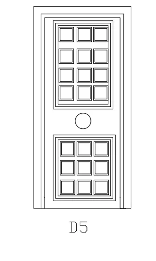
DOOR 5:
- Open AutoCAD software and open a new drawing.
- Set the necessary limits and units.
- Type the REC command window and press enter
- Specify the first point: Type (0,0) at the command prompt and press enter(starting point)
- Draw the rectangle at a point@2'10",6'11"
- To take 3" offsetting each panel in the door.
- To create one locker to the door and inserted it.
- To draw the door name Custom_door5 and converted it to the block.
- Provide the dimensions.
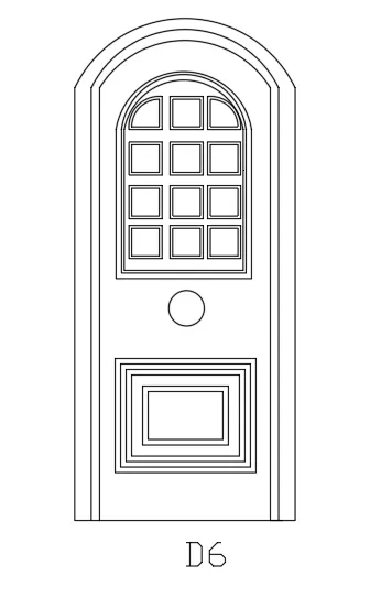
DOOR 6:
- Open AutoCAD software and open a new drawing.
- Set the necessary limits and units.
- Type the REC command window and press enter
- Specify the first point: Type (0,0) at the command prompt and press enter(starting point)
- Draw the rectangle at a point@2'10",6'11"
- To take 3" offsetting each panel in the door.
- To create one locker to the door and inserted it.
- To draw the door name it Custom_door6 and converted it to the block.
- Provide the dimensions.
FINAL RESULTS:
QUESTION-5:
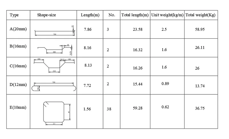
Create each shape as a block as shown in the Figure. Save the block and insert them on the table as shown in the Figure.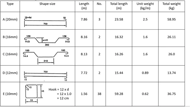
PROCEDURE:
- Open AutoCAD software and open a new drawing.
- Set the necessary limits and units.
- Type the REC command window and press enter
- Specify the first point: Type (0,0) at the command prompt and press enter(starting point)
- To draw the table as per the required sizes for reinforcement details.
- To draw each reinforcement schedule and converted it to the block and inserted it into the data required table.
- To create effective blocks for reinforcement schedules.
- After that go to the insert option and click on the field options and select the block name then inserted it into the table. The above procedure is the same for all reinforcement details.
- Finally provide text with a scale factor of 10 and also measure the dimensions.
- Final reinforcschedulehedule as shown in the result.
RESULT: