Project 1 _Creating an Architectural plan for the provided plot size and develop relevant basic structural drawings
PROJECT-1:
Creating an Architectural plan for the provided plot size and develop relevant basic structural drawings.
AIM:
To Design and Draft a layout of a residential building with the following details:
a. Plot Size: 60’x20’(18.3m x6m)
b. Orientation- Facing East
c. Develop the following: 1. Architectural Drawing (Floor Plan, Elevations, and Sections) 2. Structural Drawing (Column, Beam, Footing Plan).
INTRODUCTION:
Draw the Architectural drawings of a residential building are i) a Plan of a two-storeyed building, ii) an Elevation of a two-storeyed residential building, iii) a Section of a two-storeyed residential building, and Structural drawings of a residential building, i) Column plan layout of the building, ii)Beam plan layout of the building, iii) Footing plan layout of the building. Use proper dimension techniques and dimension styles to document the project. Assume the sizes of the doors and windows as per construction standards. Refer to sections for stair details if required. The tools are XL LINE horizontal and vertical, Draw tools, modify commands, to identify the objects layer properties are used. Mainly focus on tools in floor plan and column details are offsetting, rotating, scaling, filleting, and chamfering the sketched objects. annotations and dimensioning are mostly used in structural drawings.
1. ARCHITECTURAL DRAWINGS:
PROCEDURE:
- Open AutoCAD software and open a new drawing.
- Set the necessary limits and units.
- Type the REC command window and press enter

- Specify the first point: Type (0,0) at the command prompt and press enter(starting point)
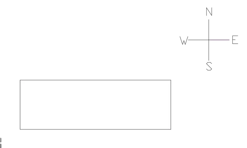
- Draw the rectangular plot size 18300 mm x 6000 mm by using the rectangular command.
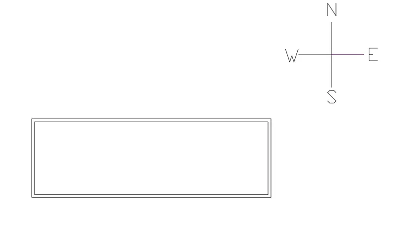
6. Now, take the offset command and draw the outer thickness wall by 230mm.
7. After that create the partition walls, stairs, doors, and windows as per nominal sizes.
D - Door PANELLED - 900X2000
D1- Door PANELLED - 750X1800
W - Window PANELLED - 1200x1200
V- ventilator Glazed - 700 x400
V1-ventilator Glazed - 900 x400
Tread=500mm
Riser- 350 mm
8. Walls are hatched by using the Hatched command, the hatching angle will be 1000.
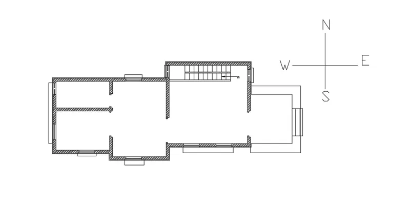
9. After that provide annotation, text, and their room sizes.
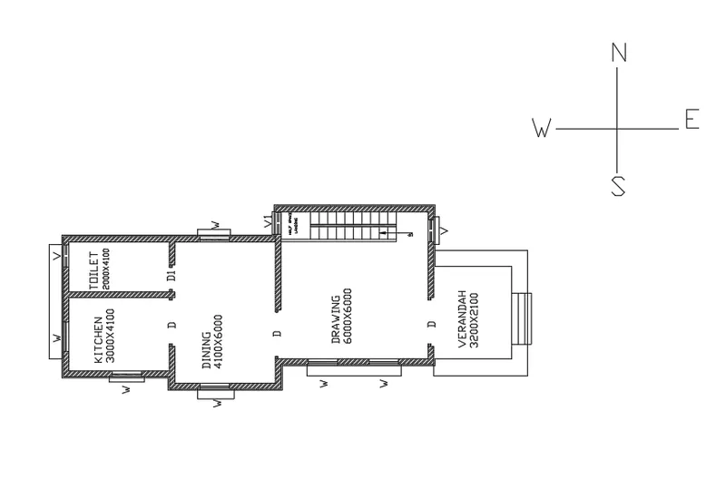
10. Next create layers and represent the Architectural drawing.
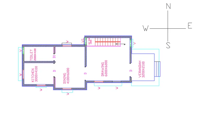
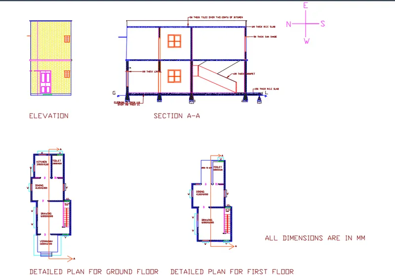
11. Above diagram represents the detailed plan of the ground floor.
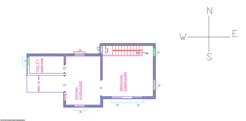
12. After completing the Ground floor plan,to draw the first-floor plan similar to the ground floor.
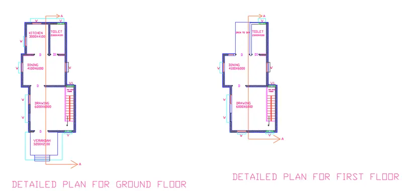
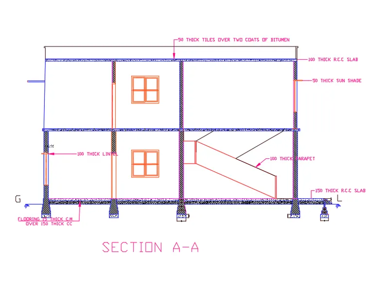
13. To create a section of two floors, it represents as A-A section.
14. To draw a section, noted the footing dimensions and represent them in a diagram respectively. East on the top side is taken.
15. To create an external walla as join together footing onwards, extra lines are trimmed by using the trim command.
16. After the completion of the walls, we have to provide windows along with lintels.
17. Lintels are provided to 100 mm thickness and also the flooring is also provided 15mm thickness concrete material over 150mm thickness.
18. Proper dimensions are used for footings as represented in the diagram.
19. After completing the lintels and sunshade we have to provide the main window paneled block as represented in the figure.
20. Slab is provided on each floor 150mm thickness and top floor 100mm thickness.
21. After that hatching is provided for sand filling, concrete, and walls.
22. Next will be annotation and text.
23. Provide all dimensions and layers inserted.
24. After that rotation is done towards the East facing the top.
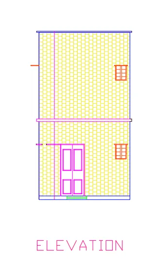
25. To draw the Elevation of the drawing, First, we take xl lines by using the XL command after that projected for walls, doors, and windows.
26. After that draw the doors as per the above nominal sizes we get the proper door paneled elevation.
27. Similarly we have to draw the windows for the ground floor and first floor.
28. After that Hatching is provided for the remaining portion by brick pattern and color is provided that brick lines.
29. Layers are provided.
30. Finally to complete the Ground floor, First floor, Sections A-A, and elevation of the Two storeyed residential building of plot size 60'x20'(18300 mm x 6000mm)
31. To take All dimensions are in mm.
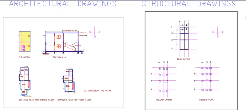
32. Final results of the Architectural drawing for Two storeyed residential building is represented below.
2. STRUCTURAL DRAWINGS:
PROCEDURE:
1. COLUMN LAYOUT:
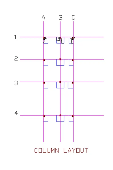
- First we draw grid lines represented as horizontally A, B, and C and vertically 1,2,3, and 4 respectively.
- The column is mentioned as per residential building we have to assume the dimensions for each column are 10'' x24''.
- Proper placing is done by columns and noting down the dimensions.
- Hatching is provided for each column.
- Typical layout as shown below.
RESULT:
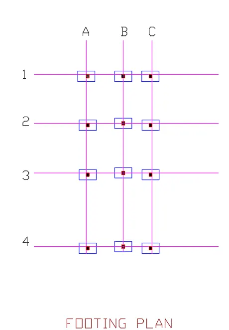
2. FOOTING PLAN:
- First we draw grid lines represented as horizontally A, B, and C and vertically 1,2,3, and 4 respectively.
- The column is mentioned as per residential building we have to assume the dimensions for each column are 10'' x24'' and also measured to the footing pit distance is 914.4mm(3ft)x1524mm(5ft).
- Proper placement and depth of footing are the most important in while construction of residential buildings.
- Hatching is provided for each footing line represented in the drawing.
- Typical layout as shown below.
RESULT:
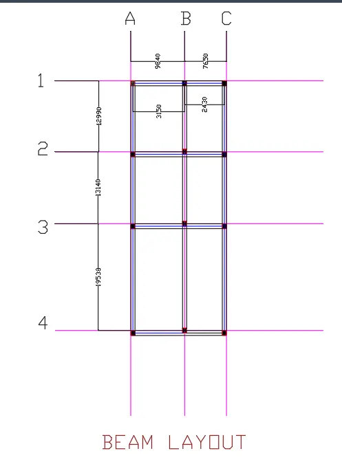
3. BEAM LAYOUT:
- First we draw grid lines represented as horizontally A, B, and C and vertically 1,2,3, and 4 respectively.
- After completing the column and footing layouts we designed the beam layout.
- In that beam layout we provided only the direction of the beams presented in the drawing.
- Dimension of the beam will be considered based on the dimension of the columns.
- Based on the column layout we are drawing the beam layout.
- Hatching will be provided for each beam.
RESULT:
- Final structural drawing results are shown in below.
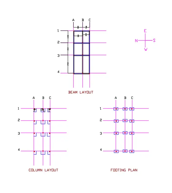
- Final results to develop an entire project of 1. Architectural Drawing (Floor Plan, Elevations, and Sections) 2. Structural Drawing (Column, Bean, Footing Plan) are,