Sketch a G+1 residential plan according to Vaastu Shastra and Calculation of Loads as per IS code
Aim: To provide a G+1 residential plan as per Vastu Shastra.
Introduction:
Vaastu Shastra
- Vaastu Shastra is the ancient science of architecture and acts as a guideline to design your home in a way that enhances positive energy.
- Our nature is abundant with energy sources like the sun, wind, moon, water, earth and fire.
- Effect of sunrays, the flow of winds, pull of earth's magnetic field and other such cosmic energies.
- A good home needs to radiate the right kind of energy.
- A person dwelling in a house comes under the influence of a specific energy field, which comes under the influence of a particular energy field.
- Architectural changes are not possible for a ready to move in house.
- Significance of eight directions-
- There are four cardinals directions: North East West South.
- For intercardinal directions, there are: North East, North West, South East, South West
- Each direction signifies an aspect of life and is governed by various gods.
- North depicts wealth; South depicts Dharma; West & East depicts overall prosperity.
Auspicious direction as per Vaastu Shastra
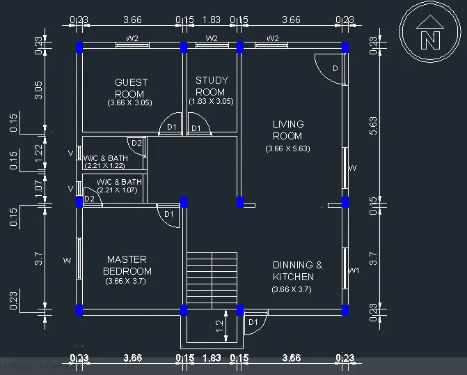
- Living Room
- North-West is the best.
- The entrance is in the northwest corner facing east direction.
- Electric appliances can be placed on the eastern wall of the living room.
- Furniture can be placed in the southwest corner of the room.
- Kitchen
- South-East is considered to be the best.
- The ground floor plan is given below the kitchen is placed in the South-East direction of the residential building.
- as per Vaastu Shastra kitchen is separated from the washroom totally.
- Master Bedroom
- South-west is considered to be the best.
- The bed is placed on the southwest corner of the wall while the head resting in the west direction.
- Guest Room
- North-West is considered to be the best.
- As per the plan the guest room is placed in the northwest direction.
- A bed is placed in the west wall of the room for the head resting in the west direction.
- Toilet
- North-west is considered to be the best.
Important structural drawings for a project:
- Centre-line drawing.
- This the first drawing to be provided to the site engineer on site.
- This drawing contains the specific position of the columns for the particular projects.
- The Structural Designer should provide all the standard values in the NOTES section of the drawing.
- Gridlines on the x-axis are denoted numerically, and gridlines on the y-axis are denoted alphabetically.
- Footing and column layout with reinforcement details.
- As the grid line is already in place, the column marking and footing are marked on the ground for excavation work.
- The outer dimension of the footing is for PCC.
- All the footing with the same dimension is marked as the same denotation for future reference.
- Each column and footing is denoted in this drawing for future construction.
- Column schedule with reinforcement details.
- This drawing provides all the reinforcement details for the footing and column provided in the structure.
- This drawing provides a standard column and footing of structure for reference.
- For a particular column and footing number of bars, size of bars, the position of bars, length of stirrups, number of stirrups, spacing of bars, spacing of stirrups etc. is given in the drawing.
- Plinth beam layout with reinforcement details.
- All the plinth beams are shown.
- Plinth beams are denotation start from the bottom left corner of the drawing. First, the horizontal columns are denoted from bottom to top, then the vertical columns are marked from left to right.
- The primary beam, which is connected to columns, is shown separately having cranked edges.
- As for secondary beam which is connected to primary beam, they are shown with straight edges.
- First-floor beams with reinforcement details.
- All the reinforcement details for each beam is given in detail.
- Beams grouping and denotation is done the same as plinth beam is done.
- A minimum of 4 bars is provided for the beam.
- If the required area of steel is not fulfilled, then the diameter of the bars increases or extra bars are provided in between the top and bottom bars of the beam.
- First-floor slab layout with reinforcement details.
- We have all the reinforcement details regarding the slab.
- For one way slab, the main steel(which carries the load from slab to beam) is provided along the shorter span of the slab, and the distribution steel is provided along the longer span of the slab.
- For two way slab, main steel is provided in both the direction of the slab.
- All the main steel bars are cranked before they get into beams.
- Distribution steel bars are not cranked at the edges.
- Lift-pit and headrooms with reinforcement details.
- The footing of the lift pit is generally provided with RCC walls, as shown in the figure to provide strength and avoid seepage into the lift pit.
- The construction is the same as it is for the shear wall.
- This drawing contains all the details required for reinforcement for the lift pit, such as the foundation for the lift pit, reinforcement for RCC walls, position for beams and lintel beams(for brick masonry wall), reinforcement for columns, etc.
Following is the Ground Floor plan as per Vaastu Shastra:
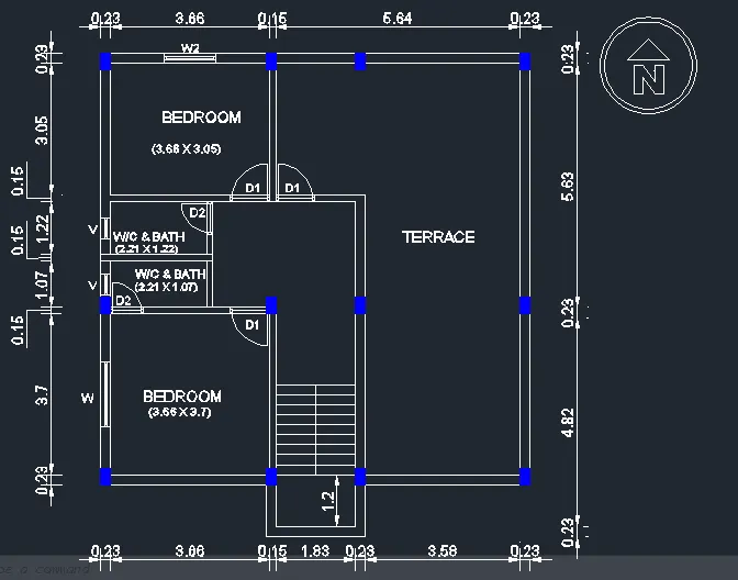
Following is the First Floor plan as per Vaastu Shastra:
Scheduling for doors:
| Scheduling of doors | |
| Denotation for Door | Size of Door(b×h)(in meter) |
| D | (1.2×2.1) |
| D1 | (0.9×2.1) |
| D2 | (0.75×2.1) |
Scheduling for Windows and ventilator:
| Scheduling for Windows and ventilator | |
| Denotation for Windows and Ventilator | Size of Door(b×h)(in meter) |
| W | (1.5×1.5) |
| W1 | (1.5×1.0) |
| W2 | (1.2×1.2) |
| V | (0.5×0.75) |
Assumed Values:
- All the measurements are in meter(m).
- The thickness of the outer walls is 0.230m.
- The thickness of internal walls is 0.150m.
- column size : 0.23m×0.38m.
- Beam size:0.23m×0.30m.
- The thickness of the slab: 200mm.
- Floor to floor height: 3.05m.
- Lintel level: 2.1m from the floor.
- Staircase:
- Tread= 0.23m.
- Riser=0.162m.
- Landing= 1.2m.
- Location: Nasik(outskirts of city area)
-
ϴ= 2˚.
Calculation of Dead Load:
- Dead load of slab:
- slab thickness= 200mm =0.200m.
- Slab area= 1`m^2`
- Unit weight of concrete= 25`(kN)/m^3`
- Dead Load of slab= 25×1×0.200= 5`(kN)/m^2`
- Dead load of beam:
- size of Beam= 230mm×300mm=0.23×0.300
- Width of beam= 1m
- volume of concrete= 0.23×0.3×1= 0.069`m^3`
- unit weight of concrete= 25`(kN)/m^3`
- Dead Load of beam per meter= 0.135×25= 1.725 `(kN)/m`
- Dead load of column:
- size of column= 230mm×380mm=0.23×0.38
- height of column= 3.05m
- volume of concrete= 0.23×0.38×3.05= 0.405`m^3`
- unit weight of concrete= 25`(kN)/m^3`
- Dead Load of each column= 0.405×25= 6.664 kN
- Dead load of walls:
- External walls:
- Length of external walls=1m.
- width of External wall= 0.230m
- Height of external wall= 3.05m
- unit weight of brick wall= 20 `(kN)/m^3`
- The dead load of the External brick wall= 1×0.23×3.05×20=14.03 kN/m.
- Internal walls:
- Length of Internal walls= 1m.
- width of Internal wall= 0.150m
- Height of Internal wall= 3.05m
- unit weight of brick wall= 20 `(kN)/m^3`
- The dead load of the Internal brick wall= 1×0.15×3.05×20=9.15kN/m
- External walls:
Calculation of Live Load(Imposed Load):
- The structure is a residential building.
- As per Table 1 IS875:1987
- For all rooms and kitchen imposed load is taken as 2`(kN)/m^2`.
- For toilet and bathroom imposed load is taken as 2`(kN)/m^2`.
- For corridors,passages, staircases including tire escapes and store rooms imposed load is taken as 3`(kN)/m^2`.
- For Balconies imposed load is taken as 3`(kN)/m^2`.
Calculation of Wind load:
- Design Wind speed:
- basic wind speed= 39m/s.(From annexure A IS875:2015)
- `k_1`= 1.0 (Table 1 IS 875 Part3:2015)
- `k_2`= 1.05 (Table 2 IS 875 Part3:2015)
- `k_3`= 1.0 (clause 6.3.3 IS 875 Part3:2015)
- `k_4`= 1.0 (clause 6.3.4 IS 875 Part3:2015)
- therefore;
- `V_z=V_b×k_1×k_2×k_3×k_4`
- `V_z=39×1×1.05×1×1= 40.95m/s`
- Design Wind Pressure:
- `p_z=0.6V_z^2`
- `p_z=0.6×40.95^2=1006.14 N/m^2`
- Wind load:
- `F=(C_(pe)-C_(p i)).A.p_d`
- `h/w= 0.32`
- `l/w= 1.26`
- Therefore from above values the value of `C_(pe)`= -0.8 (clause 7.3.3 Table 5 IS 875 Part3:2015)
- Assuming the opening in the building is in between 5%-20%
- `C_(p i)`= `+-0.5` (clause 7.3.2.1 IS 875 Part3:2015`
- A= 101.230`m^2`
- `F=(-0.8-(0.5))×101.230×1006.14= -13.240 kN`
- `F=(C_(pe)-C_(p i)).A.p_d`
Results:
- Dead Load:
- Dead Load of slab= 5`(kN)/m^2`.
- Dead Load of beam per meter= 1.725 `(kN)/m`.
- Dead Load of each column= 6.664 kN.
- The dead load of the External brick wall=14.03 kN/m.
- The dead load of the Internal brick wall=9.15kN/m.
- Imposed load:
- All rooms and Kitchen= 2`(kN)/m^2`.
- Toilet and Bathroom = 2`(kN)/m^2`.
- Corridors, Passages, Staircases including tire escapes and Store rooms= 3`(kN)/m^2`.
- Balconies= 3`(kN)/m^2`.
- Wind load:
- Wind load for whole structure=-13.240 kN