Creating a Floor plan, Footing detail and Isometric view using AutoCad
AIM:
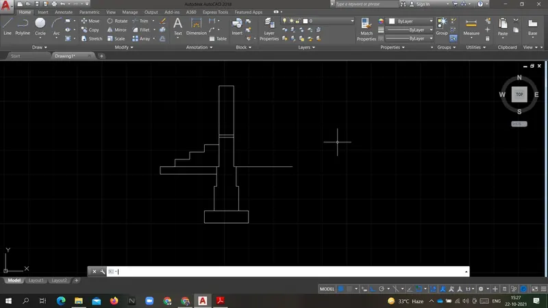
To Create a Cross-section of a load-bearing wall over spread footing using AUTOCAD.
INTRODUCTION:
Following are the commands which are used to draw the objects in AUTOCAD:
- Rectangle(REC): It is used to create a rectangle with the desired dimension.
- Polygon(POL): It is used to create a polygon by giving the no. of sides and circumscribed about circle or Inscribed in a circle.
- Lines(L): Used to create a line. each line is created independently.
- Polyline(PL): Used to create a set of lines and curves(if any) to create an object of the desired dimension.
Following are the commands which are used to modify the objects in AUTOCAD:
- Move(M): It is used to move objects.
- Copy(CO): it is used to create multiple copies of the object selected.
- Offset(O): It is used to create offset from a selected object by giving the offset distance.
- Rotate(RO): It is used to rotate objects.
- Scale(SC): it is used to make the selected objects bigger or smaller by changing the scale factor.
- Fillet(F): It is used to create curved edges at the junction of two lines. radius can be adjusted as per requirement.
- Chamfer(CH): It is used to create straight edges at the junction of two lines, chamfer distance is can be adjusted.
- Snap tool(DS): It is used to set the minimum distance to move in the x & y-direction.
PROCEDURE:
Command: REC
RECTANG
Specify first corner point or [Chamfer/Elevation/Fillet/Thickness/Width]:
Specify other corner point or [Area/Dimensions/Rotation]: d
Specify length for rectangles <0.9000>: 0.9
Specify width for rectangles <0.2500>: 0.25
Specify other corner point or [Area/Dimensions/Rotation]: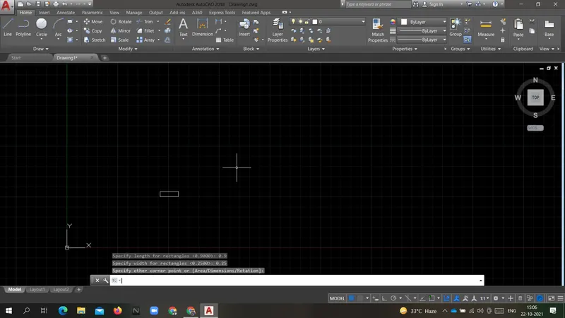
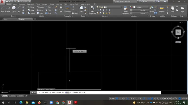
Command: _line
Specify first point:
Specify next point or [Undo]: 0.5
Specify next point or [Undo]: 0.4
Specify next point or [Close/Undo]:
Command: O OFFSET
Current settings: Erase source=No Layer=Source OFFSETGAPTYPE=0
Specify offset distance or [Through/Erase/Layer] : 0.25
Select object to offset or [Exit/Undo] :
Specify point on side to offset or [Exit/Multiple/Undo] :
Select object to offset or [Exit/Undo] :
Specify point on side to offset or [Exit/Multiple/Undo] :
Select object to offset or [Exit/Undo] :
Command: OPEN
Command:
Command: O OFFSET
Current settings: Erase source=No Layer=Source OFFSETGAPTYPE=0
Specify offset distance or [Through/Erase/Layer] <0.2500>: 0.2
Select object to offset or [Exit/Undo] :
Specify point on side to offset or [Exit/Multiple/Undo] :
Select object to offset or [Exit/Undo] :
Specify point on side to offset or [Exit/Multiple/Undo] :
Select object to offset or [Exit/Undo] :
Command: E ERASE
Select objects: 1 found
Select objects: 1 found, 2 total
Select objects: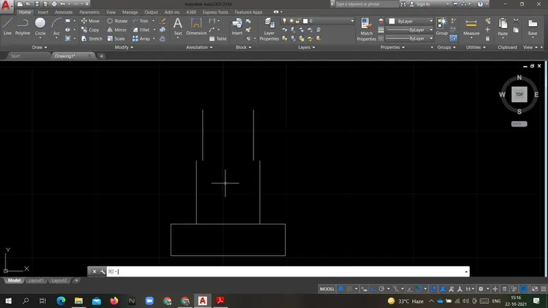
Command: L LINE
Specify first point:
Specify next point or [Undo]:
Specify next point or [Undo]:
Command: LINE
Specify first point:
Specify next point or [Undo]:
Specify next point or [Undo]:
Command: L LINE
Specify first point:
Specify next point or [Undo]:
Specify next point or [Undo]:
Command:
Command:
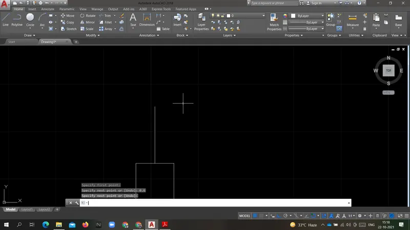
Command: _line
Specify first point:
Specify next point or [Undo]: 0.6
Specify next point or [Undo]:
Command: O OFFSET
Current settings: Erase source=No Layer=Source OFFSETGAPTYPE=0
Specify offset distance or [Through/Erase/Layer] <0.2000>: 0.15
Select object to offset or [Exit/Undo] :
Specify point on side to offset or [Exit/Multiple/Undo] :
Select object to offset or [Exit/Undo] :
Specify point on side to offset or [Exit/Multiple/Undo] :
Select object to offset or [Exit/Undo] :
Command: E ERASE
Select objects: 1 found
Select objects: 1 found, 2 total
Select objects:
Command: l LINE
Specify first point:
Specify next point or [Undo]:
Specify next point or [Undo]:
Command: LINE
Specify first point:
Specify next point or [Undo]:
Specify next point or [Undo]:
Command: LINE
Specify first point:
Specify next point or [Undo]:
Specify next point or [Undo]:
Command: O OFFSET
Current settings: Erase source=No Layer=Source OFFSETGAPTYPE=0
Specify offset distance or [Through/Erase/Layer] <0.1500>: 0.05
Select object to offset or [Exit/Undo] :
Specify point on side to offset or [Exit/Multiple/Undo] :
Command: l LINE
Specify first point:
Specify next point or [Undo]: 1
Specify next point or [Undo]:
Command: LINE
Specify first point:
Specify next point or [Undo]: 1
Specify next point or [Undo]:
Specify next point or [Close/Undo]:
Command: LINE
Specify first point:
Specify next point or [Undo]:
Specify next point or [Undo]:
Command: LINE
Specify first point:
Specify next point or [Undo]:
Command: LINE
Specify first point:
Specify next point or [Undo]:
Specify next point or [Undo]: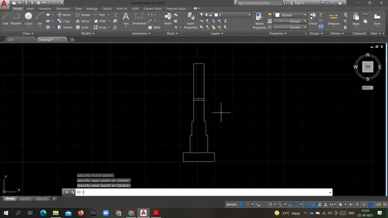
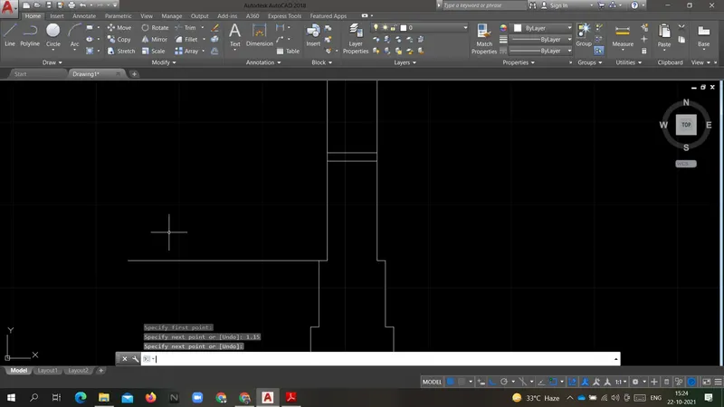
Command: _line
Specify first point:
Specify next point or [Undo]: 1.15
Specify next point or [Undo]:
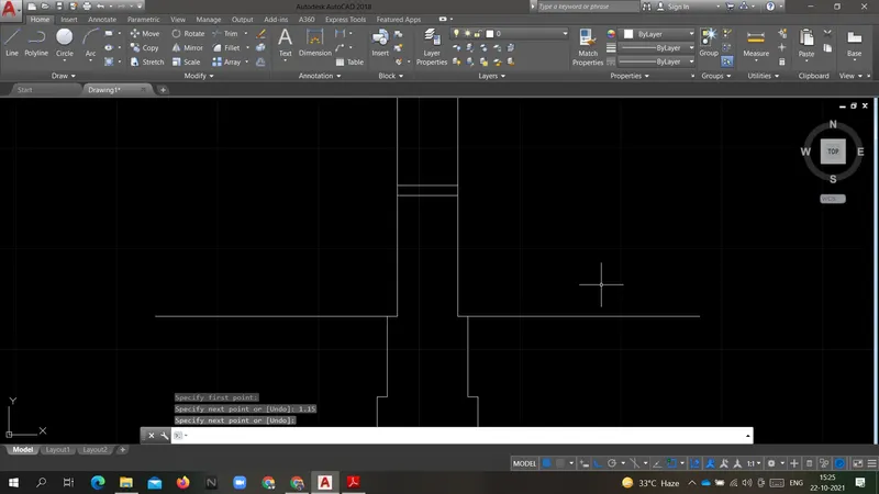
Command: LINE
Specify first point:
Specify next point or [Undo]: 1.15
Specify next point or [Undo]:
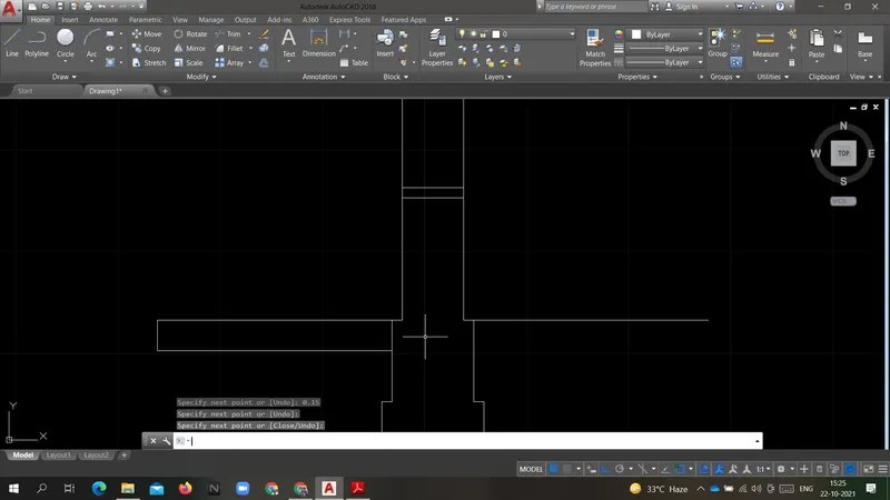
Command: L LINE
Specify first point:
Specify next point or [Undo]: 0.15
Specify next point or [Undo]:
Specify next point or [Close/Undo]:
Command: _pline
Specify start point:
Current line-width is 0.0000
Specify next point or [Arc/Halfwidth/Length/Undo/Width]: 0.30
Specify next point or [Arc/Close/Halfwidth/Length/Undo/Width]: 0.15
Specify next point or [Arc/Close/Halfwidth/Length/Undo/Width]: 0.30
Specify next point or [Arc/Close/Halfwidth/Length/Undo/Width]: 0.15
Specify next point or [Arc/Close/Halfwidth/Length/Undo/Width]: 0.30
Specify next point or [Arc/Close/Halfwidth/Length/Undo/Width]: 0.15
Specify next point or [Arc/Close/Halfwidth/Length/Undo/Width]: 0.30
Specify next point or [Arc/Close/Halfwidth/Length/Undo/Width]:
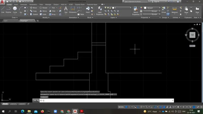
RESULT: Following is the result using AUTOCAD drawing using the above commands and dimensions.
-------------------------------------------------------------------------------------------------------------------------------------------
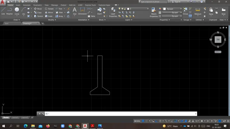
AIM: To Create a Cross-section of an isolated R.C.C. footing using AUTOCAD.
INTRODUCTION:
Following are the commands which are used to draw the objects in AUTOCAD:
- Rectangle(REC): It is used to create a rectangle with the desired dimension.
- Polygon(POL): It is used to create a polygon by giving the no. of sides and circumscribed about circle or Inscribed in a circle.
- Lines(L): Used to create a line. each line is created independently.
- Polyline(PL): Used to create a set of lines and curves(if any) to create an object of the desired dimension.
Following are the commands which are used to modify the objects in AUTOCAD:
- Move(M): It is used to move objects.
- Copy(CO): it is used to create multiple copies of the object selected.
- Offset(O): It is used to create offset from a selected object by giving the offset distance.
- Rotate(RO): It is used to rotate objects.
- Scale(SC): it is used to make the selected objects bigger or smaller by changing the scale factor.
- Fillet(F): It is used to create curved edges at the junction of two lines. radius can be adjusted as per requirement.
- Chamfer(CH): It is used to create straight edges at the junction of two lines, chamfer distance is can be adjusted.
- Snap tool(DS): It is used to set the minimum distance to move in the x & y-direction.
PROCEDURE:
Command: PL PLINE
Specify start point:
Current line-width is 0.0000
Specify next point or [Arc/Halfwidth/Length/Undo/Width]: 0.15
Specify next point or [Arc/Close/Halfwidth/Length/Undo/Width]: @0.25,0.38
Specify next point or [Arc/Close/Halfwidth/Length/Undo/Width]: U
Specify next point or [Arc/Close/Halfwidth/Length/Undo/Width]: @0.38,.25
Specify next point or [Arc/Close/Halfwidth/Length/Undo/Width]: 1.60
Specify next point or [Arc/Close/Halfwidth/Length/Undo/Width]: 0.04
Specify next point or [Arc/Close/Halfwidth/Length/Undo/Width]:
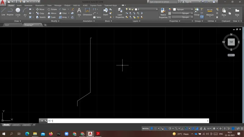
Command: L LINE
Specify first point:
Specify next point or [Undo]: 1
Specify next point or [Undo]: 0.15
Specify next point or [Close/Undo]: @-0.38,0.25
Specify next point or [Close/Undo]: 1.6
Specify next point or [Close/Undo]: 0.04
Specify next point or [Close/Undo]:
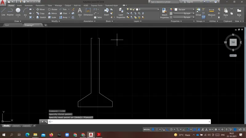
Command: LINE
Specify first point:
Specify next point or [Undo]: *Cancel*
Command: L LINE
Specify first point:
Specify next point or [Undo]:
Specify next point or [Undo]:
Command: O OFFSET
Current settings: Erase source=No Layer=Source OFFSETGAPTYPE=0
Specify offset distance or [Through/Erase/Layer] <0.0500>: 0.04
Select object to offset or [Exit/Undo] :
Specify point on side to offset or [Exit/Multiple/Undo] :
Select object to offset or [Exit/Undo] :
Specify point on side to offset or [Exit/Multiple/Undo] :
Select object to offset or [Exit/Undo] :
Specify point on side to offset or [Exit/Multiple/Undo] :
Select object to offset or [Exit/Undo] :
Specify point on side to offset or [Exit/Multiple/Undo] :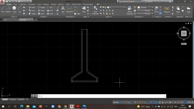
Command: _explode 2 found
Command:
Command: _.erase 1 found
Command:
Command:
** STRETCH **
Specify stretch point or [Base point/Copy/Undo/eXit]:
Command:
Command:
** STRETCH **
Specify stretch point or [Base point/Copy/Undo/eXit]:
Command:
Command:
** STRETCH **
Specify stretch point or [Base point/Copy/Undo/eXit]:
Command:
Command:
** STRETCH **
Specify stretch point or [Base point/Copy/Undo/eXit]:
Command:
Command:
** STRETCH **
Specify stretch point or [Base point/Copy/Undo/eXit]:
Command:
Command:
** STRETCH **
Specify stretch point or [Base point/Copy/Undo/eXit]:
Command: *Cancel*
Command:
Command:
** STRETCH **
Specify stretch point or [Base point/Copy/Undo/eXit]: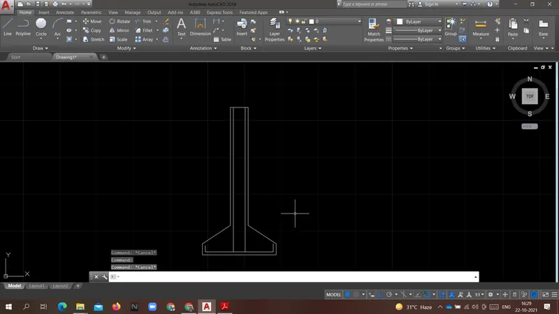
Command:
Command: e ERASE
Select objects: 1 found
Select objects:
Command: L LINE
Specify first point:
Specify next point or [Undo]:
Specify next point or [Undo]:
Command: LINE
Specify first point:
Specify next point or [Undo]:
Specify next point or [Undo]:
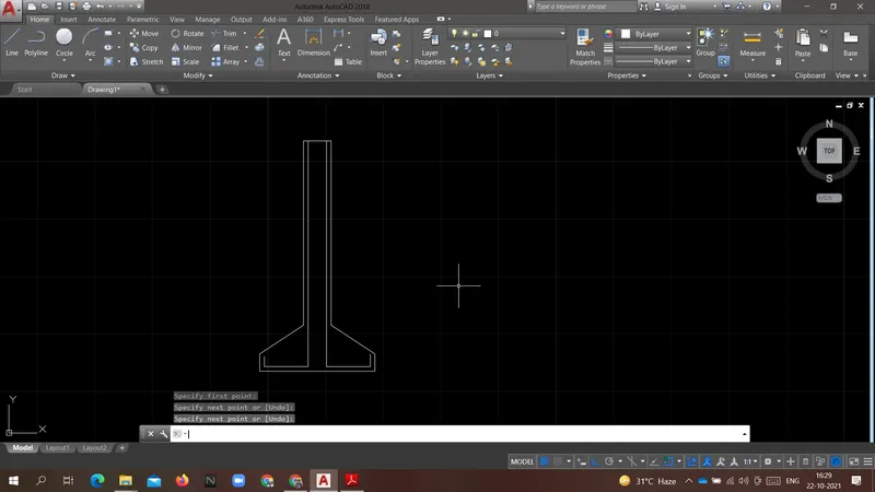
Command: O OFFSET
Current settings: Erase source=No Layer=Source OFFSETGAPTYPE=0
Specify offset distance or [Through/Erase/Layer] <0.0400>: 0.20
Select object to offset or [Exit/Undo] :
Specify point on side to offset or [Exit/Multiple/Undo] :
Select object to offset or [Exit/Undo] :
Specify point on side to offset or [Exit/Multiple/Undo] :
Select object to offset or [Exit/Undo] :
Specify point on side to offset or [Exit/Multiple/Undo] :
Select object to offset or [Exit/Undo] :
Specify point on side to offset or [Exit/Multiple/Undo] :
Select object to offset or [Exit/Undo] :
Specify point on side to offset or [Exit/Multiple/Undo] :
Select object to offset or [Exit/Undo] :
Specify point on side to offset or [Exit/Multiple/Undo] :
Select object to offset or [Exit/Undo] :
Specify point on side to offset or [Exit/Multiple/Undo] :
Select object to offset or [Exit/Undo] :
Specify point on side to offset or [Exit/Multiple/Undo] :
Select object to offset or [Exit/Undo] :
Specify point on side to offset or [Exit/Multiple/Undo] :
Select object to offset or [Exit/Undo] :
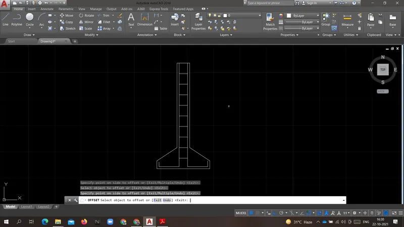
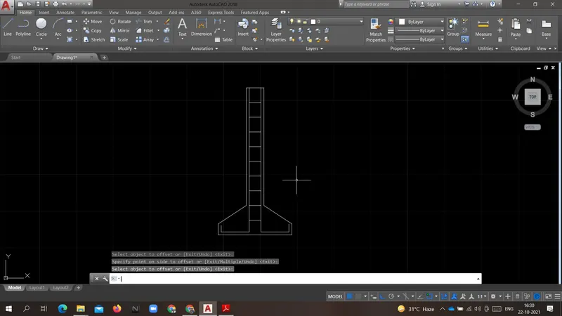
RESULT: The image below shows a Cross-section of an isolated R.C.C. footing using AUTOCAD.
------------------------------------------------------------------------------------------------------------------------------------------
AIM: To Create a line diagram of a two-bedroom building using AUTOCAD.
INTRODUCTION:
Following are the commands which are used to draw the objects in AUTOCAD:
- Rectangle(REC): It is used to create a rectangle with the desired dimension.
- Polygon(POL): It is used to create a polygon by giving the no. of sides and circumscribed about the circle or Inscribed in a circle.
- Lines(L): Used to create a line. each line is created independently.
- Polyline(PL): Used to create a set of lines and curves(if any) to create an object of the desired dimension.
Following are the commands which are used to modify the objects in AUTOCAD:
- Move(M): It is used to move objects.
- Copy(CO): it is used to create multiple copies of the object selected.
- Offset(O): It is used to create offset from a selected object by giving the offset distance.
- Rotate(RO): It is used to rotate objects.
- Scale(SC): it is used to make the selected objects bigger or smaller by changing the scale factor.
- Fillet(F): It is used to create curved edges at the junction of two lines. radius can be adjusted as per requirement.
- Chamfer(CH): It is used to create straight edges at the junction of two lines, chamfer distance is can be adjusted.
- Snap tool(DS): It is used to set the minimum distance to move in the x & y-direction.
PROCEDURE:
Command: L LINE
Specify first point:
Specify next point or [Undo]: 0.3
Specify next point or [Undo]: 0.3
Specify next point or [Close/Undo]: 0.3
Specify next point or [Close/Undo]: 3.6
Specify next point or [Close/Undo]: 3.6
Specify next point or [Close/Undo]: 3.6
Specify next point or [Close/Undo]: 0.3
Specify next point or [Close/Undo]: 0.3
Specify next point or [Close/Undo]: 0.3
Specify next point or [Close/Undo]: 1
Specify next point or [Close/Undo]: 0.3
Specify next point or [Close/Undo]: .3
Specify next point or [Close/Undo]: .3
Specify next point or [Close/Undo]: 4.20
Specify next point or [Close/Undo]: 3.6
Specify next point or [Close/Undo]: 4.2
Specify next point or [Close/Undo]: .3
Specify next point or [Close/Undo]: .3
Specify next point or [Close/Undo]: .3
Specify next point or [Close/Undo]: c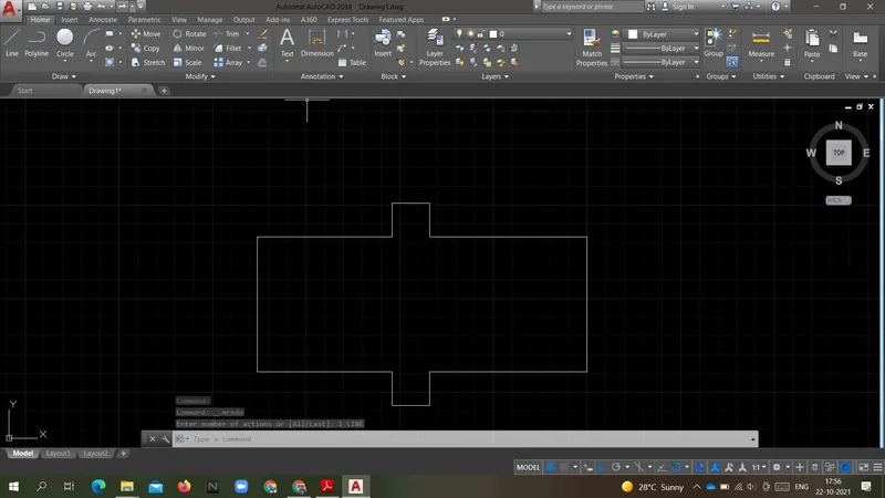
Command: L LINE
Specify first point:
Specify next point or [Undo]:
Specify next point or [Undo]:
Command: LINE
Specify first point:
Specify next point or [Undo]:
Specify next point or [Undo]:
Command: LINE
Specify first point:
Specify next point or [Undo]: 0.9
Specify next point or [Undo]:
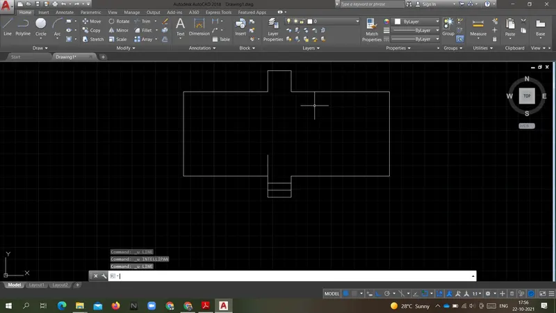
Command: L LINE
Specify first point:
Specify next point or [Undo]: 1.8
Specify next point or [Undo]:
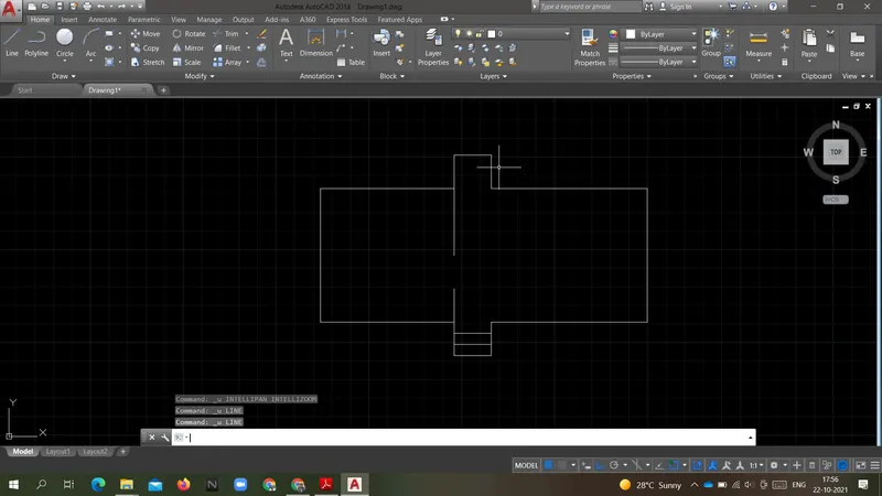
Command: l LINE
Specify first point:
Specify next point or [Undo]:
Specify next point or [Undo]:
Command: LINE
Specify first point:
Specify next point or [Undo]:
Specify next point or [Undo]:
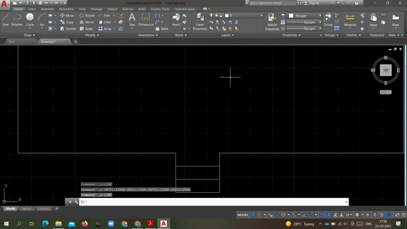
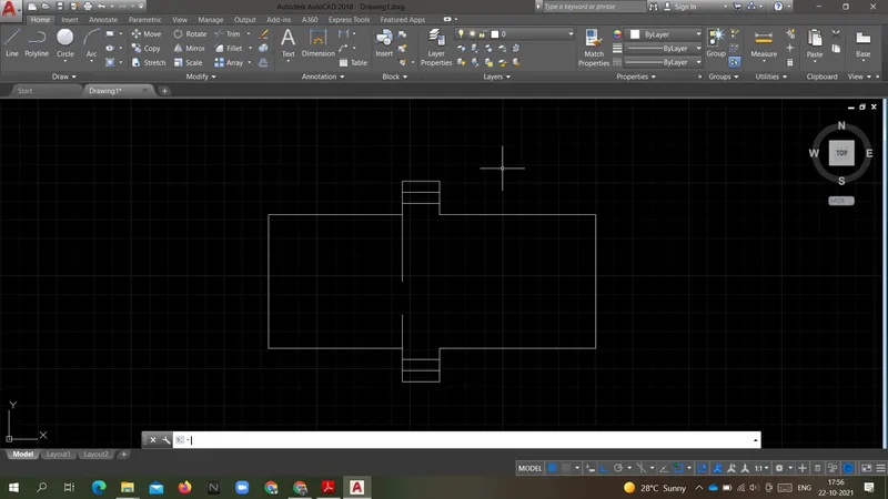
RESULT: The image below shows a line diagram of a two-bedroom building using AUTOCAD.
-------------------------------------------------------------------------------------------------------------------------------------------
AIM: To create the crosssection of load bearing wall showing foundation details using AUTOCAD.
INTRODUCTION:
Following are the commands which are used to draw the objects in AUTOCAD:
- Rectangle(REC): It is used to create a rectangle with the desired dimension.
- Polygon(POL): It is used to create a polygon by giving the no. of sides and circumscribed about circle or Inscribed in a circle.
- Lines(L): Used to create a line. each line is created independently.
- Polyline(PL): Used to create a set of lines and curves(if any) to create an object of the desired dimension.
Following are the commands which are used to modify the objects in AUTOCAD:
- Move(M): It is used to move objects.
- Copy(CO): it is used to create multiple copies of the object selected.
- Offset(O): It is used to create offset from a selected object by giving the offset distance.
- Rotate(RO): It is used to rotate objects.
- Scale(SC): it is used to make the selected objects bigger or smaller by changing the scale factor.
- Fillet(F): It is used to create curved edges at the junction of two lines. radius can be adjusted as per requirement.
- Chamfer(CH): It is used to create straight edges at the junction of two lines, chamfer distance is can be adjusted.
- Snap tool(DS): It is used to set the minimum distance to move in the x & y-direction.
PROCEDURE:
Command: L LINE
Specify first point:
Specify next point or [Undo]: 0.45
Specify next point or [Undo]: 0.4
Specify next point or [Close/Undo]: 0.3
Specify next point or [Close/Undo]: 0.6
Specify next point or [Close/Undo]: 1
Specify next point or [Close/Undo]: c
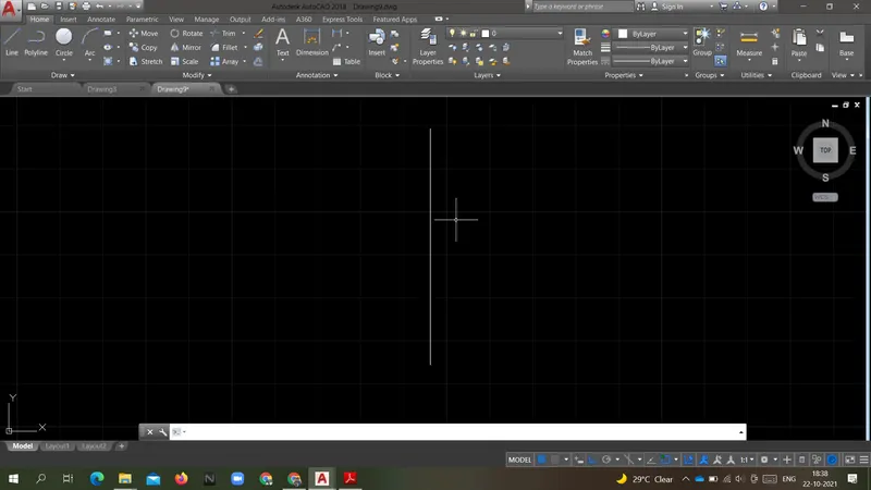
Command: O OFFSET
Current settings: Erase source=No Layer=Source OFFSETGAPTYPE=0
Specify offset distance or [Through/Erase/Layer] <0.4500>: 0.45
Select object to offset or [Exit/Undo] :
Specify point on side to offset or [Exit/Multiple/Undo] :
Select object to offset or [Exit/Undo] :
Specify point on side to offset or [Exit/Multiple/Undo] :
Select object to offset or [Exit/Undo] :
Command: OFFSET
Current settings: Erase source=No Layer=Source OFFSETGAPTYPE=0
Specify offset distance or [Through/Erase/Layer] <0.4500>: *Cancel*
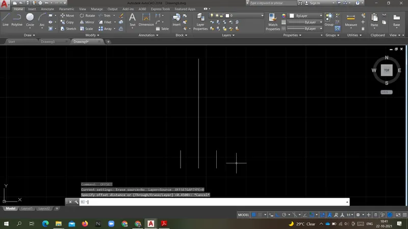
Command: OFFSET
Current settings: Erase source=No Layer=Source OFFSETGAPTYPE=0
Specify offset distance or [Through/Erase/Layer] <0.4500>: 0.3
Select object to offset or [Exit/Undo] :
Specify point on side to offset or [Exit/Multiple/Undo] :
Select object to offset or [Exit/Undo] :
Specify point on side to offset or [Exit/Multiple/Undo] :
Select object to offset or [Exit/Undo] :
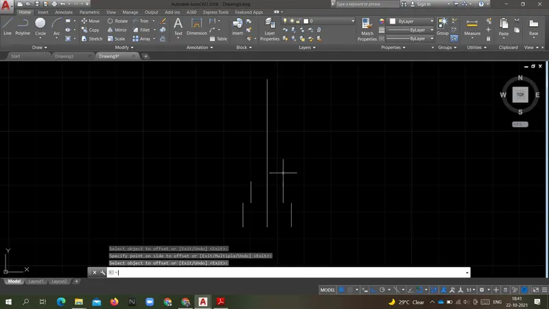
Command: OFFSET
Current settings: Erase source=No Layer=Source OFFSETGAPTYPE=0
Specify offset distance or [Through/Erase/Layer] <0.3000>: 0.25
Select object to offset or [Exit/Undo] :
Specify point on side to offset or [Exit/Multiple/Undo] :
Select object to offset or [Exit/Undo] :
Specify point on side to offset or [Exit/Multiple/Undo] :
Select object to offset or [Exit/Undo] :
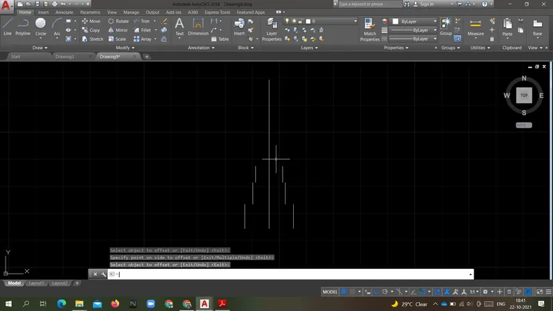
Command: OFFSET
Current settings: Erase source=No Layer=Source OFFSETGAPTYPE=0
Specify offset distance or [Through/Erase/Layer] <0.2500>: 0.2
Select object to offset or [Exit/Undo] :
Specify point on side to offset or [Exit/Multiple/Undo] :
Select object to offset or [Exit/Undo] :
Specify point on side to offset or [Exit/Multiple/Undo] :
Select object to offset or [Exit/Undo] :
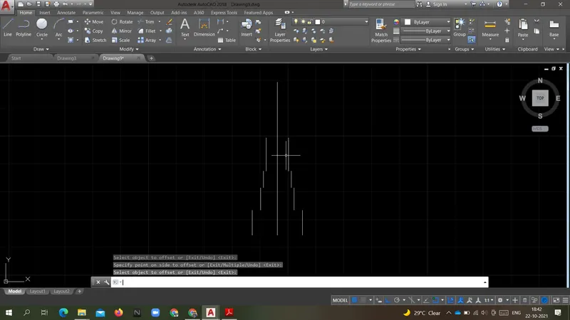
Command: OFFSET
Current settings: Erase source=No Layer=Source OFFSETGAPTYPE=0
Specify offset distance or [Through/Erase/Layer] <0.2000>: 0.15
Select object to offset or [Exit/Undo] :
Specify point on side to offset or [Exit/Multiple/Undo] :
Select object to offset or [Exit/Undo] :
Specify point on side to offset or [Exit/Multiple/Undo] :
Select object to offset or [Exit/Undo] :
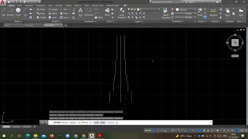
Command: E ERASE
Select objects: 1 found
Select objects: 1 found, 2 total
Select objects: 1 found, 3 total
Select objects: 1 found, 4 total
Select objects: 1 found, 5 total
Select objects:
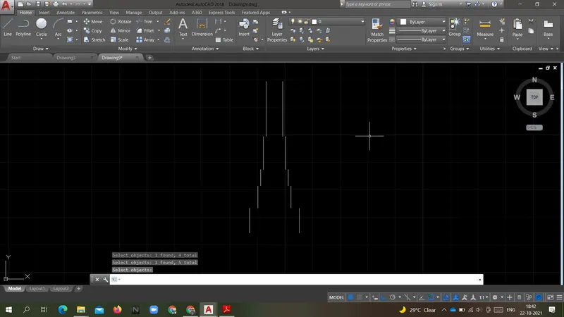
Command: L LINE
Specify first point:
Specify next point or [Undo]:
Specify next point or [Undo]:
Command: LINE
Specify first point:
Specify next point or [Undo]:
Specify next point or [Undo]:
Command: LINE
Specify first point:
Specify next point or [Undo]:
Specify next point or [Undo]:
Command: LINE
Specify first point:
Specify next point or [Undo]:
Specify next point or [Undo]:
Command: LINE
Specify first point:
Specify next point or [Undo]:
Command: LINE
Specify first point:
Specify next point or [Undo]:
Specify next point or [Undo]:
Command: LINE
Specify first point:
Specify next point or [Undo]:
Command: LINE
Specify first point:
Specify next point or [Undo]:
Specify next point or [Undo]:
Command: LINE
Specify first point:
Specify next point or [Undo]:
Specify next point or [Undo]:
Command: LINE
Specify first point:
Specify next point or [Undo]:
Specify next point or [Undo]:
Command: LINE
Specify first point:
Specify next point or [Undo]:
Specify next point or [Undo]:
Command: LINE
Specify first point:
Specify next point or [Undo]:
Specify next point or [Undo]:
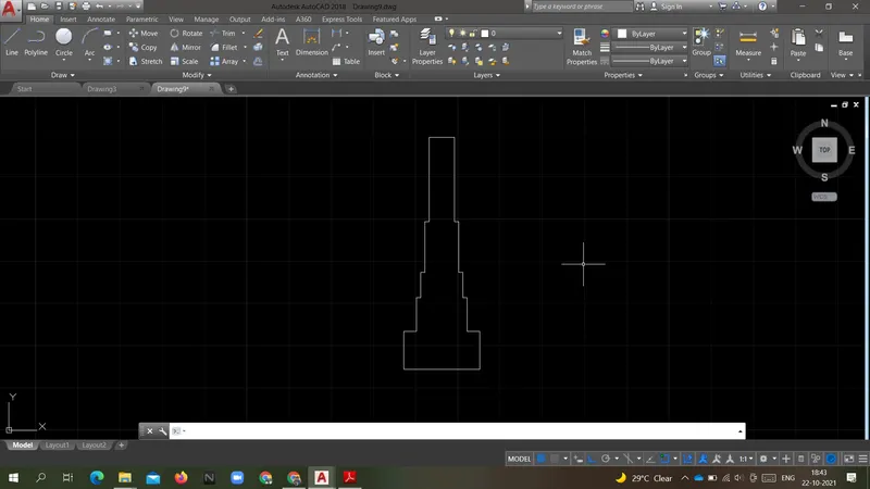
RESULT: Above image shows a cross-section of a load-bearing wall showing foundation details.
-------------------------------------------------------------------------------------------------------------------------------------------
AIM: To create an isometric view of steps by using AUTOCAD.
INTRODUCTION:
Isometric view is the 3D visualization of the object in 2D by combining top view side views of the object.
The command is "ISODRAFT" after that we have to choose the plane to work in with, those are given as follows.
- isoplane Left
- isoplane Top
- isoplane Right
PROCEDURE:
Enter an option [Orthographic/isoplane Left/isoplane Top/isoplane Right] :_Left
Command:
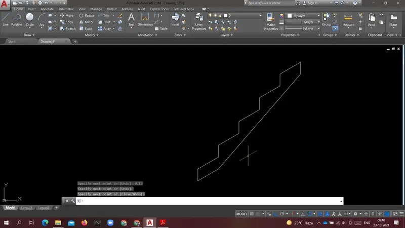
Command: l LINE
Specify first point:
Specify next point or [Undo]: 0.15
Specify next point or [Undo]: 0.30
Specify next point or [Close/Undo]: 0.15
Specify next point or [Close/Undo]: 0.30
Specify next point or [Close/Undo]: 0.15
Specify next point or [Close/Undo]: 0.30
Specify next point or [Close/Undo]: 0.15
Specify next point or [Close/Undo]: 0.30
Specify next point or [Close/Undo]: 0.15
Specify next point or [Close/Undo]: 0.30
Specify next point or [Close/Undo]:
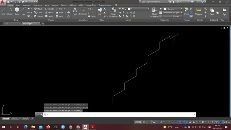
Command: L LINE
Specify first point:
Specify next point or [Undo]: 0.30
Specify next point or [Undo]:
Command: LINE
Specify first point:
Specify next point or [Undo]: 0.15
Specify next point or [Undo]:
Specify next point or [Close/Undo]:
Command:
Command: L LINE
Specify first point:
Specify next point or [Undo]: 1
Specify next point or [Undo]:
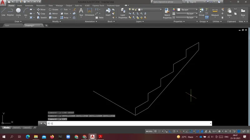
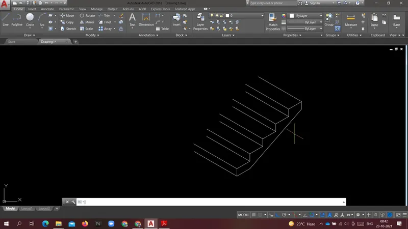
Command: CO COPY
Select objects: 1 found
Select objects:
Current settings: Copy mode = Multiple
Specify base point or [Displacement/mOde] :
Specify second point or [Array] :
Specify second point or [Array/Exit/Undo] :
Specify second point or [Array/Exit/Undo] :
Specify second point or [Array/Exit/Undo] :
Specify second point or [Array/Exit/Undo] :
Specify second point or [Array/Exit/Undo] :
Specify second point or [Array/Exit/Undo] :
Specify second point or [Array/Exit/Undo] :
Specify second point or [Array/Exit/Undo] :
Specify second point or [Array/Exit/Undo] :
Specify second point or [Array/Exit/Undo] :
Command: _line
Specify first point:
Specify next point or [Undo]:
Specify next point or [Undo]: _.ISODRAFT
Point or option keyword required.
Specify next point or [Undo]: _Orthographic
Point or option keyword required.
Specify next point or [Undo]:
Specify next point or [Close/Undo]:
Specify next point or [Close/Undo]:
Specify next point or [Close/Undo]:
Specify next point or [Close/Undo]:
Specify next point or [Close/Undo]:
Specify next point or [Close/Undo]:
Specify next point or [Close/Undo]:
Specify next point or [Close/Undo]: u
Specify next point or [Close/Undo]: u
Specify next point or [Close/Undo]:
Specify next point or [Close/Undo]:
Specify next point or [Close/Undo]:
Specify next point or [Close/Undo]:
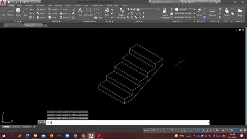
RESULT: This is the final Isometric image of the Steps.
-------------------------------------------------------------------------------------------------------------------------------------------
AIM: To create the isometric view of gable wall using AUTOCAD.
INTRODUCTION:
Isometric view is the 3D visualization of the object in 2D by combining top view side views of the object.
The command is "ISODRAFT" after that we have to choose the plane to work in with, those are given as follows.
- isoplane Left
- isoplane Top
- isoplane Right
PROCEDURE:
Enter an option [Orthographic/isoplane Left/isoplane Top/isoplane Right] :_Right
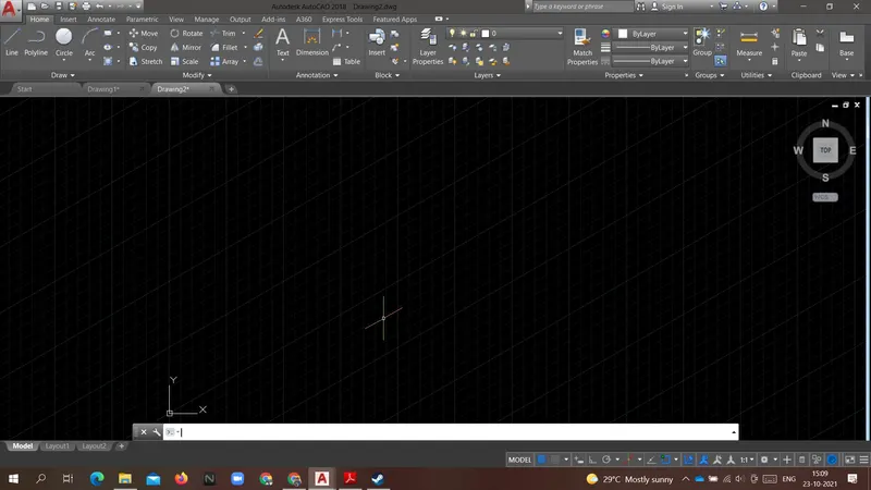
Command: L LINE
Specify first point:
Specify next point or [Undo]: 3
Specify next point or [Undo]: 1
Specify next point or [Close/Undo]: 2.42
Specify next point or [Close/Undo]: 1
Specify next point or [Close/Undo]: 2.42
Specify next point or [Close/Undo]: 1
Specify next point or [Close/Undo]: 3
Specify next point or [Close/Undo]:
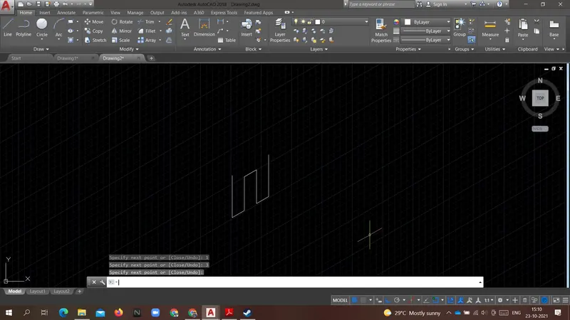
Command: L LINE
Specify first point:
Specify next point or [Undo]:
Specify next point or [Undo]:
Command: L LINE
Specify first point:
Specify next point or [Undo]: 0.25
Specify next point or [Undo]:
Command: L LINE
Specify first point:
Specify next point or [Undo]:
Specify next point or [Undo]:
Specify next point or [Close/Undo]:
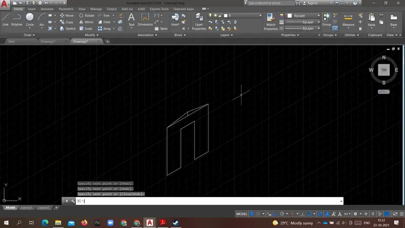
Command:
Command: l LINE
Specify first point:
Specify next point or [Undo]: 0.3
Specify next point or [Undo]:
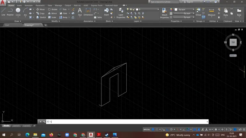
Command: CO COPY
Select objects: 1 found
Select objects:
Current settings: Copy mode = Multiple
Specify base point or [Displacement/mOde] :
Specify second point or [Array] :
Specify second point or [Array/Exit/Undo] :
Specify second point or [Array/Exit/Undo] :
Specify second point or [Array/Exit/Undo] :
Specify second point or [Array/Exit/Undo] :
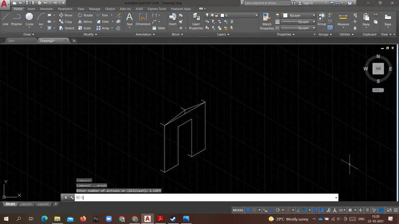
Command: L LINE
Specify first point:
Specify next point or [Undo]:
Specify next point or [Undo]:
Command: LINE
Specify first point:
Specify next point or [Undo]:
Specify next point or [Undo]:
Command: LINE
Specify first point:
Specify next point or [Undo]:
Specify next point or [Undo]:
Command: LINE
Specify first point:
Specify next point or [Undo]:
Specify next point or [Undo]:
Command:
Command:
** STRETCH **
Specify stretch point or [Base point/Copy/Undo/eXit]: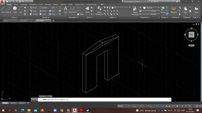
Command: E ERASE
Select objects: 1 found
Select objects: 1 found, 2 total
Select objects:
Command:
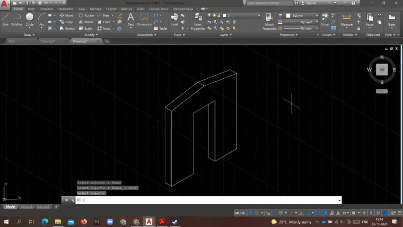
RESULT: This is the final Isometric image of the Gable wall.
-------------------------------------------------------------------------------------------------------------------------------------------