Creation of geometries by Coordinate system methods using AutoCad
Aim: To create the geometries of the P1 form above using different coordinates system methods.
Introduction: there are different types of coordinate systems that can be used.
- Absolute coordinate system.
- In this system, the absolute location of the point is given as an input.
- Always the origin(0,0) is the reference point for all the points in the geometry.
- Relative coordinates system.
- Relative rectangular coordinates system.
- This system is based on the previous location of the point.
- Once the first point is given the next point will take the previous point as a reference point.
- Taking the previous point as a reference point the coordinate of the next point is given.
- Relative polar coordinates system.
- In this coordinate system, the relative distance and angle are given with the previous point.
- angle is given with respect to the positive x-axis(by default).
- Relative rectangular coordinates system.
- Direct distance entry.
- In this coordinate system first, we provide the direction with the mouse and we have to input the distance.
Procedure:
Absolute coordinate system.
Command: L LINE
Specify first point: 2,1
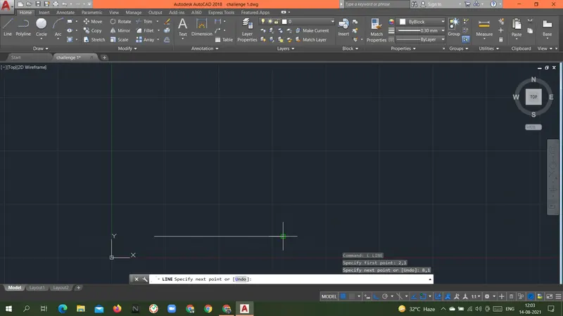
Specify next point or [Undo]: 8,1
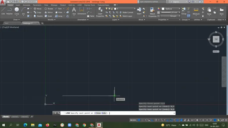
Specify next point or [Undo]: 8,2
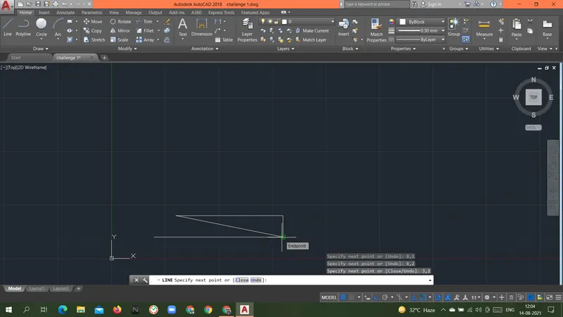
Specify next point or [Close/Undo]: 3,2
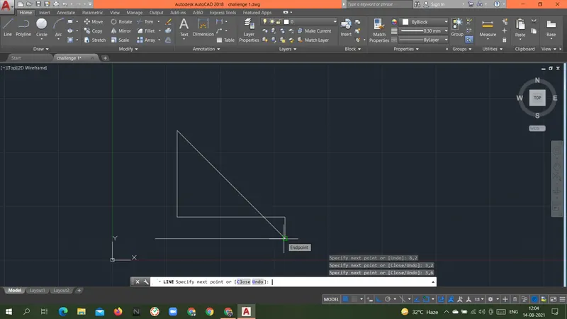
Specify next point or [Close/Undo]: 3,6
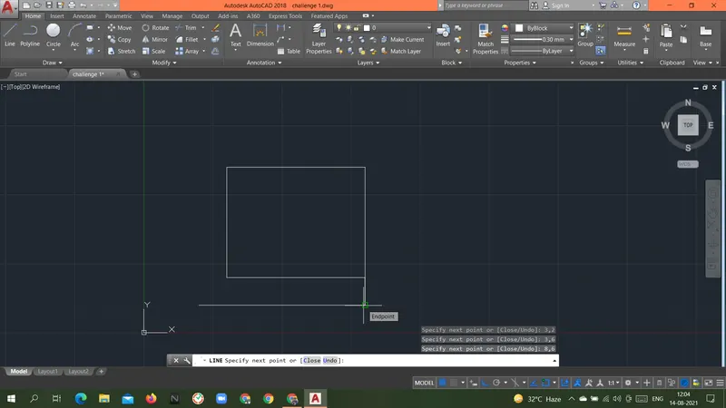
Specify next point or [Close/Undo]: 8,6
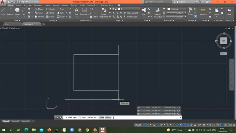
Specify next point or [Close/Undo]: 8,7
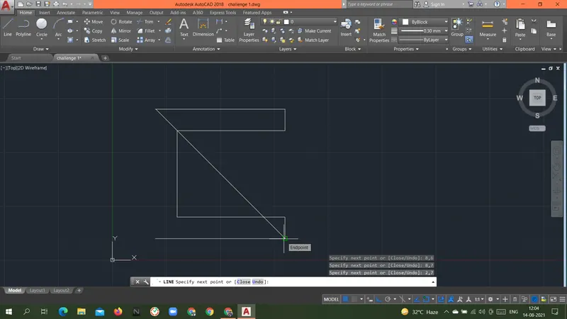
Specify next point or [Close/Undo]: 2,7
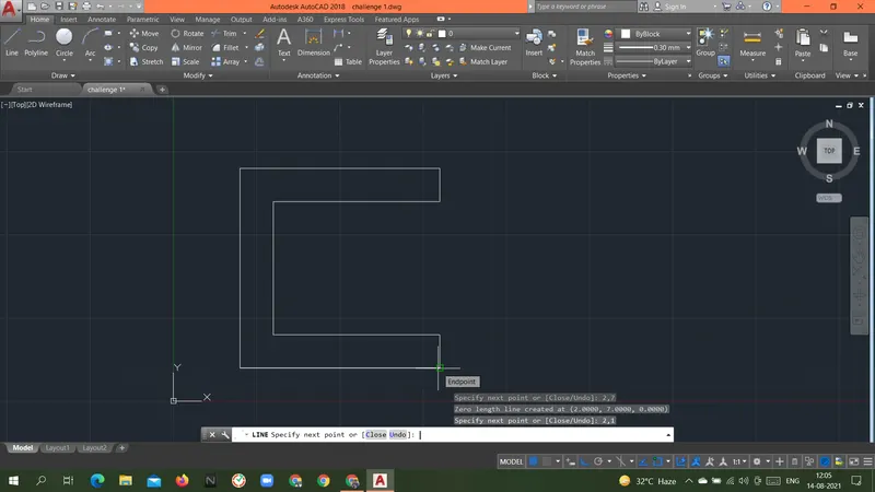
Specify next point or [Close/Undo]: 2,1
Specify next point or [Close/Undo]: c
Result: Above geometry P1 was drawn with an absolute coordinate system.
Relative rectangular coordinates system.
Command: L
LINE
Specify first point: 2,1
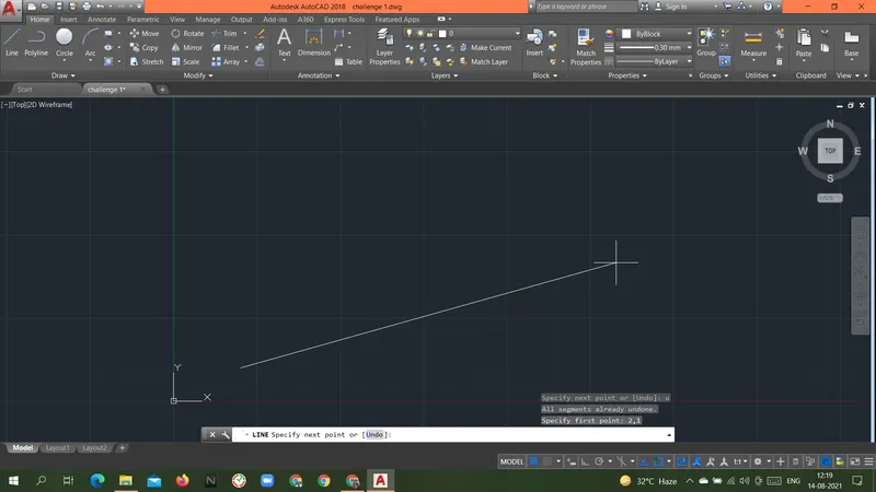
Specify next point or [Undo]: @6,0
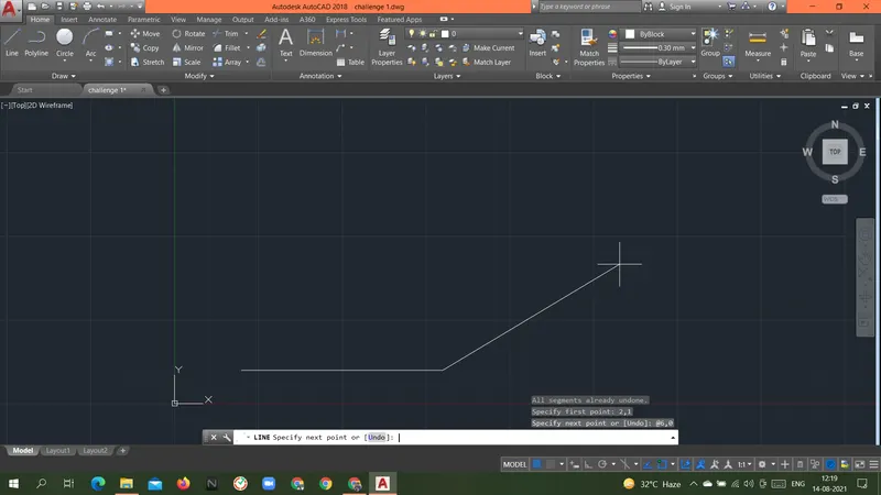
Specify next point or [Undo]: @0,1
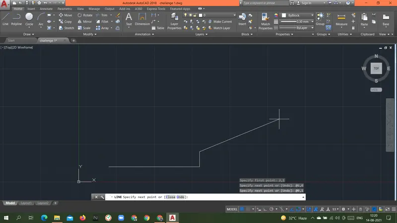
Specify next point or [Close/Undo]: @-5,0
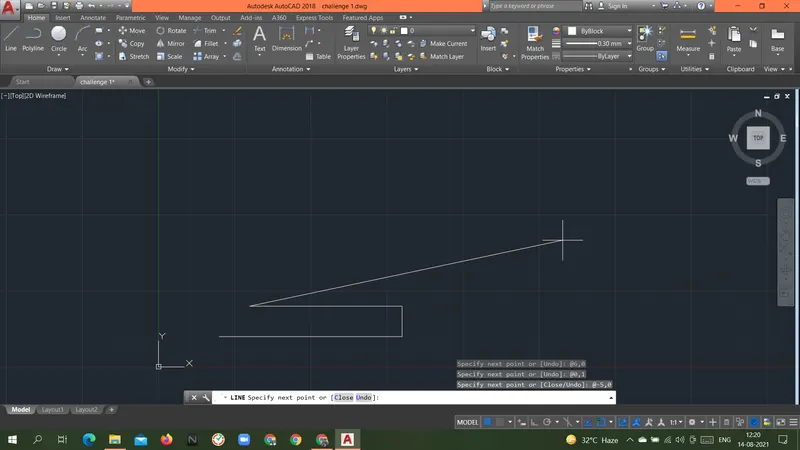
Specify next point or [Close/Undo]: @0,4
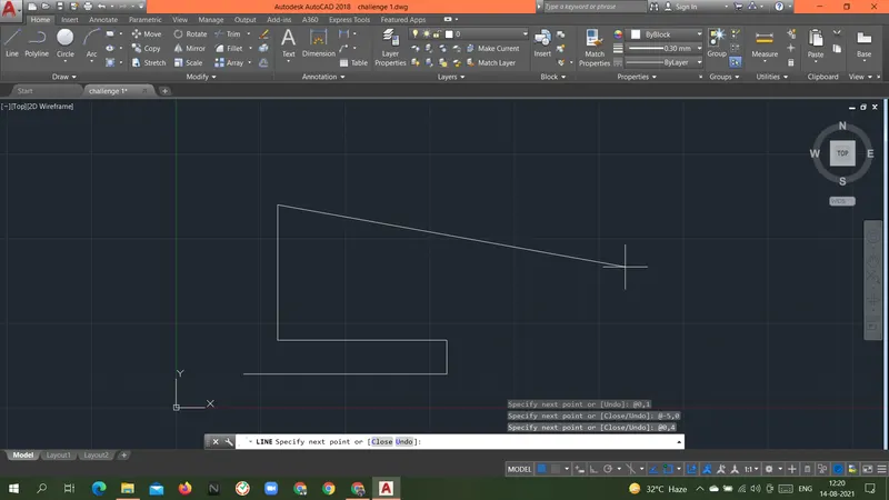
Specify next point or [Close/Undo]: @5,0
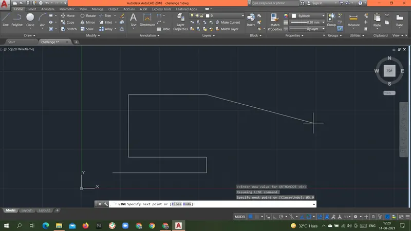
Specify next point or [Close/Undo]: @0,1
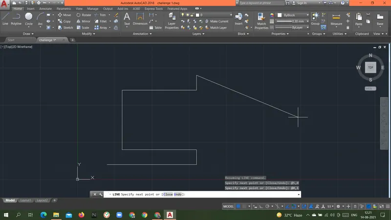
Specify next point or [Close/Undo]: @-6,0
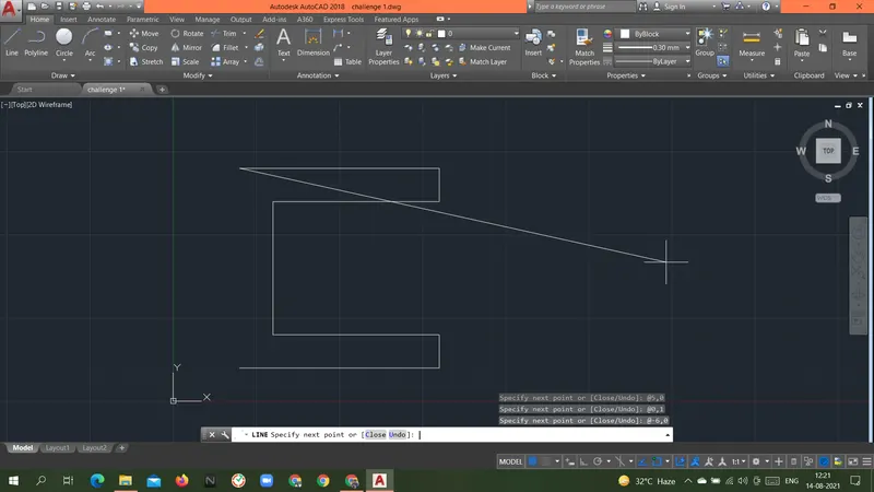
Specify next point or [Close/Undo]: @0,-6
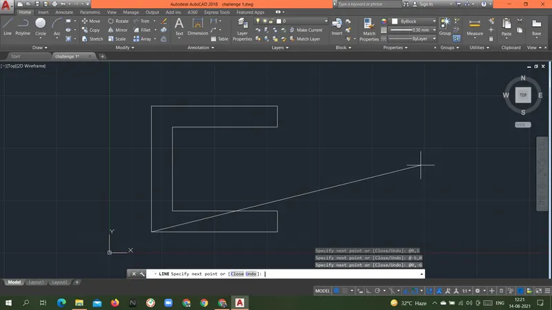
Specify next point or [Close/Undo]: c
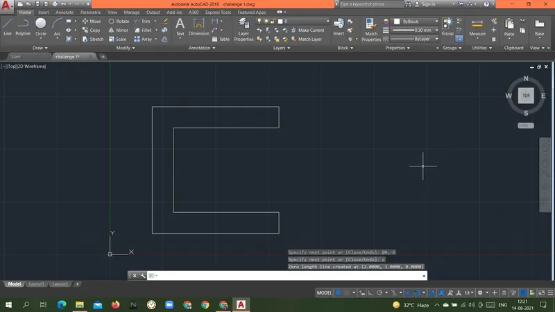
Result: Above geometry P1 was drawn with a Relative rectangular coordinate system.
Relative polar coordinates system.
Command: L
LINE
Specify first point: 2,1
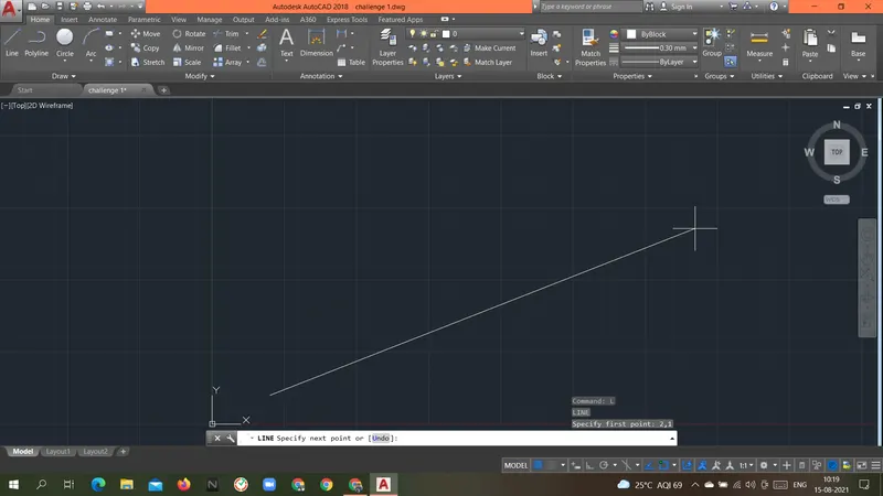
Specify next point or [Undo]: @6<0
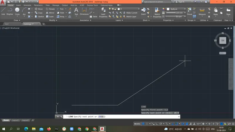
Specify next point or [Undo]: @1<90
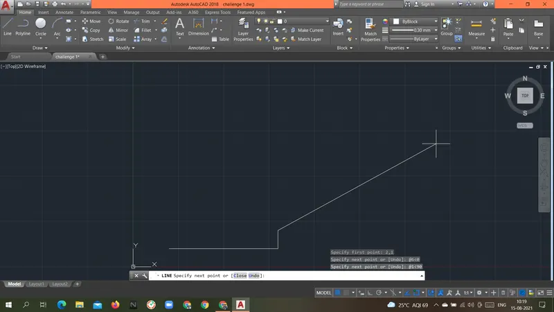
Specify next point or [Close/Undo]: @5<180
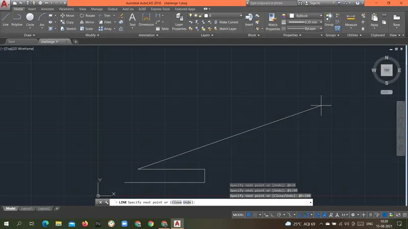
Specify next point or [Close/Undo]: @4<90
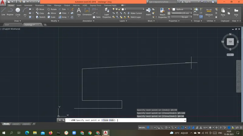
Specify next point or [Close/Undo]: @5<0
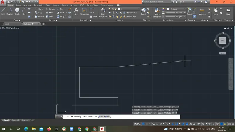
Specify next point or [Close/Undo]: @1<90
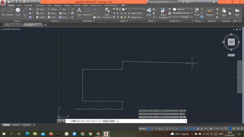
Specify next point or [Close/Undo]: @6<180
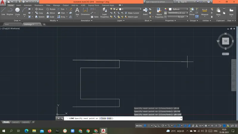
Specify next point or [Close/Undo]: @6<270
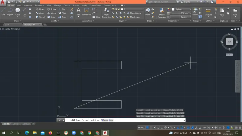
Specify next point or [Close/Undo]: c
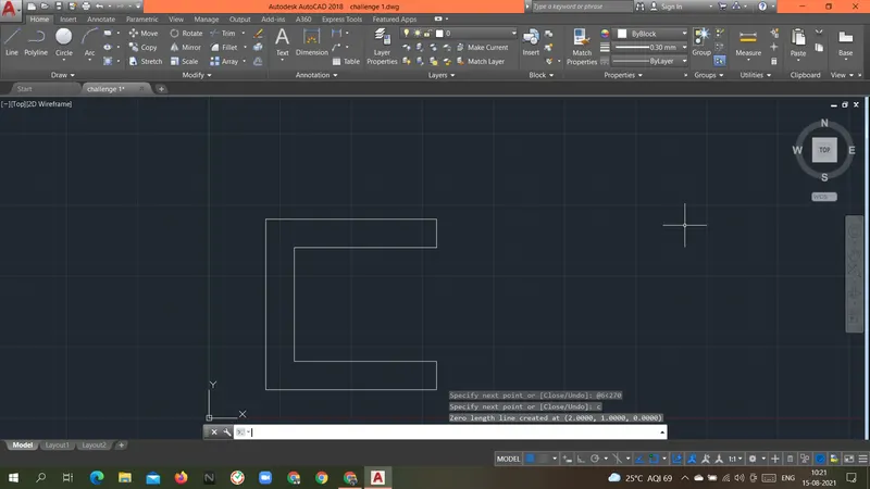
Result: Above geometry P1 was drawn with a Relative polar coordinate system.
Direct distance entry method.
Command: L
LINE
Specify first point: 2,1
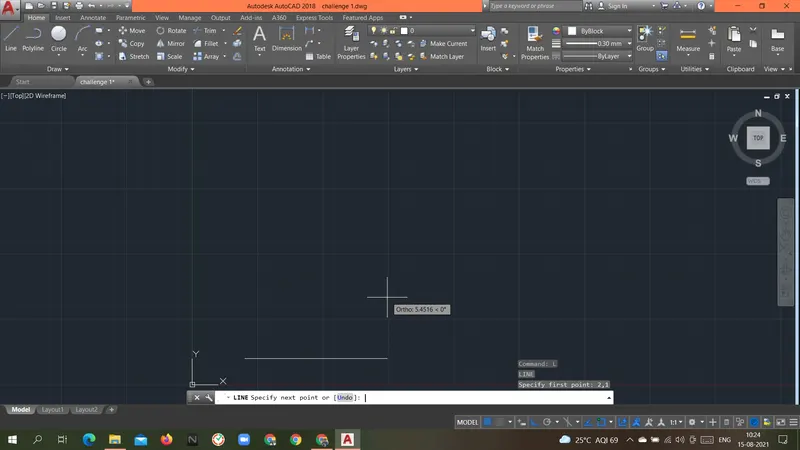
Specify next point or [Undo]: 6
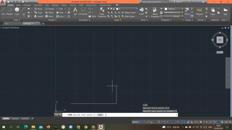
Specify next point or [Undo]: 1
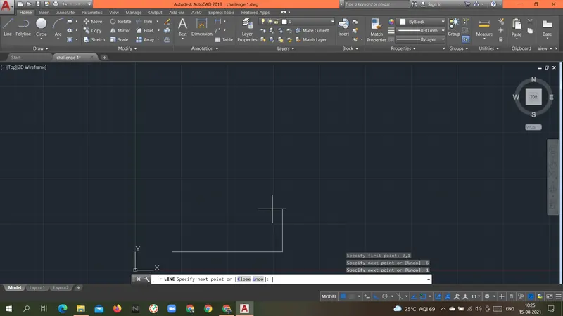
Specify next point or [Close/Undo]: 5
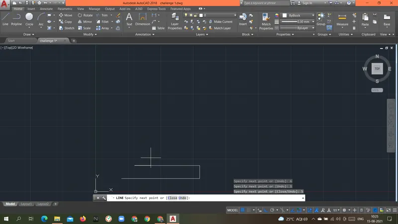
Specify next point or [Close/Undo]: 4
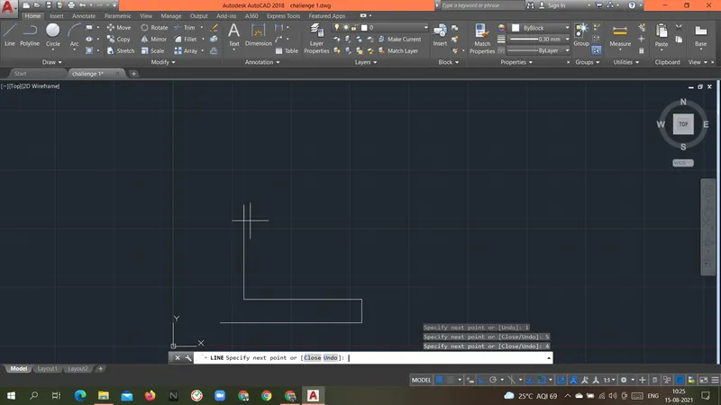
Specify next point or [Close/Undo]: 5
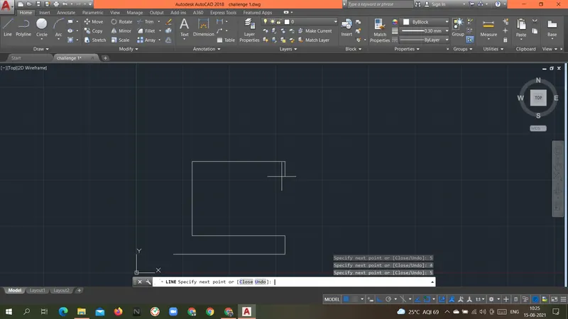
Specify next point or [Close/Undo]: 1
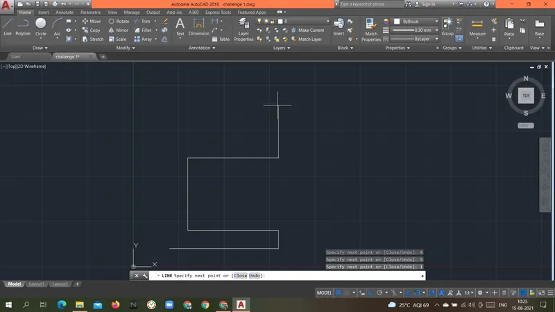
Specify next point or [Close/Undo]: 6
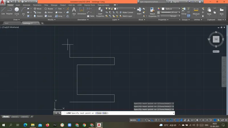
Specify next point or [Close/Undo]: 6
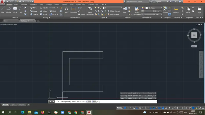
Specify next point or [Close/Undo]: c
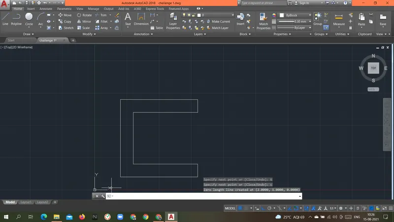
Result: Above geometry P1 was drawn with a Direct distance entry method.
----------------------------------------------------------------------------------------------------------------------------------------------------------------------------
Aim: To create the geometries of the P2 form above using different coordinates system methods.
Introduction: there are different types of coordinate systems that can be used.
- Absolute coordinate system.
- In this system, the absolute location of the point is given as an input.
- Always the origin(0,0) is the reference point for all the points in the geometry.
- Relative coordinates system.
- Relative rectangular coordinates system.
- This system is based on the previous location of the point.
- Once the first point is given the next point will take the previous point as a reference point.
- Taking the previous point as a reference point the coordinate of the next point is given.
- Relative polar coordinates system.
- In this coordinate system, the relative distance and angle are given with the previous point.
- angle is given with respect to the positive x-axis(by default).
- Relative rectangular coordinates system.
- Direct distance entry.
- In this coordinate system first, we provide the direction with the mouse and we have to input the distance.
Procedure:
Absolute coordinate system.
Command: L LINE
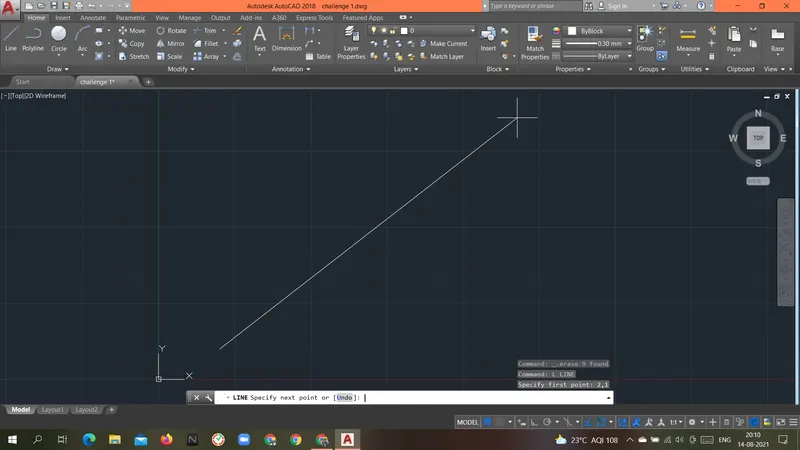
Specify first point: 2,1
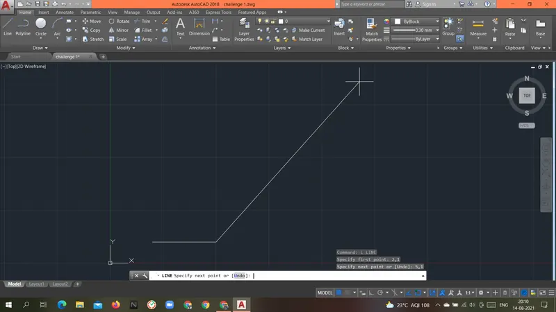
Specify next point or [Undo]: 5,1
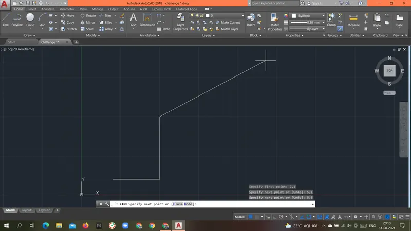
Specify next point or [Undo]: 5,5
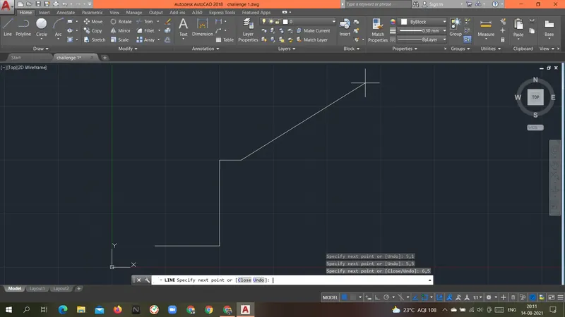
Specify next point or [Close/Undo]: 6,5
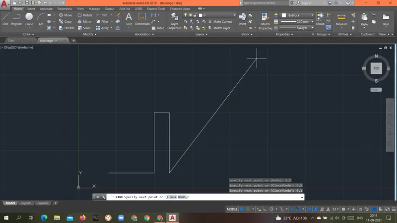
Specify next point or [Close/Undo]: 6,1
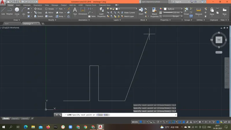
Specify next point or [Close/Undo]: 9,1
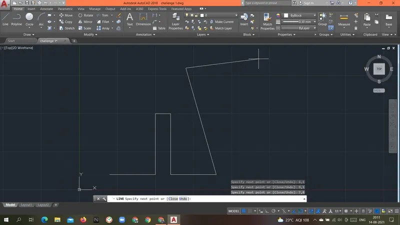
Specify next point or [Close/Undo]: 7,8
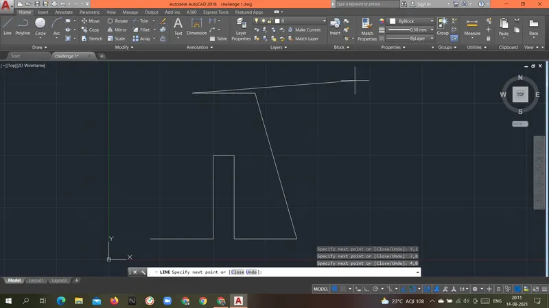
Specify next point or [Close/Undo]: 4,8
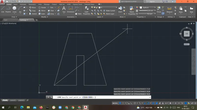
Specify next point or [Close/Undo]: 2,1
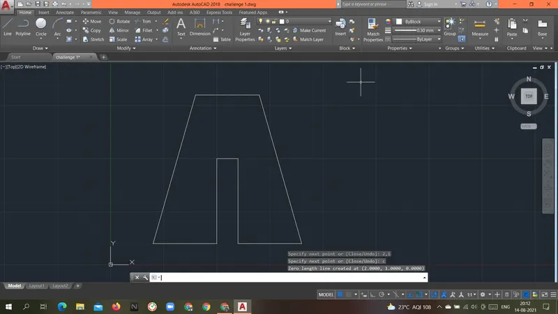
Specify next point or [Close/Undo]: c
Result: Above geometry P2 was drawn with an absolute coordinate system.
Relative rectangular coordinates system.
Procedure:
Command: L
LINE
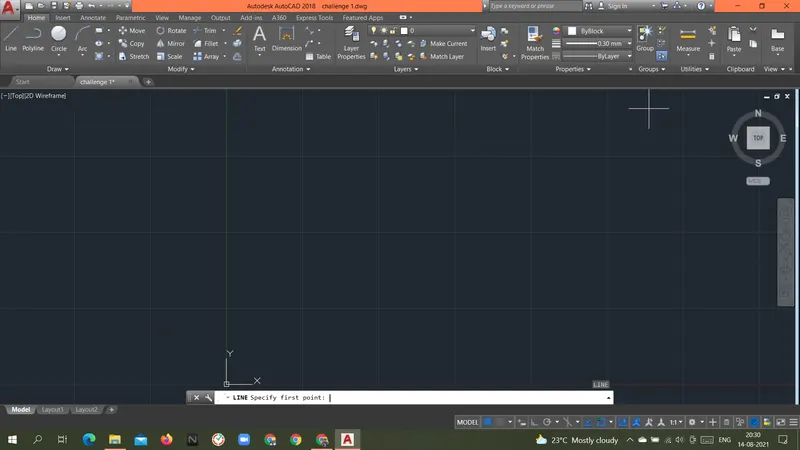
Specify first point: 2,1
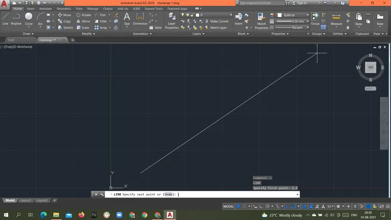
Specify next point or [Undo]: @3,0
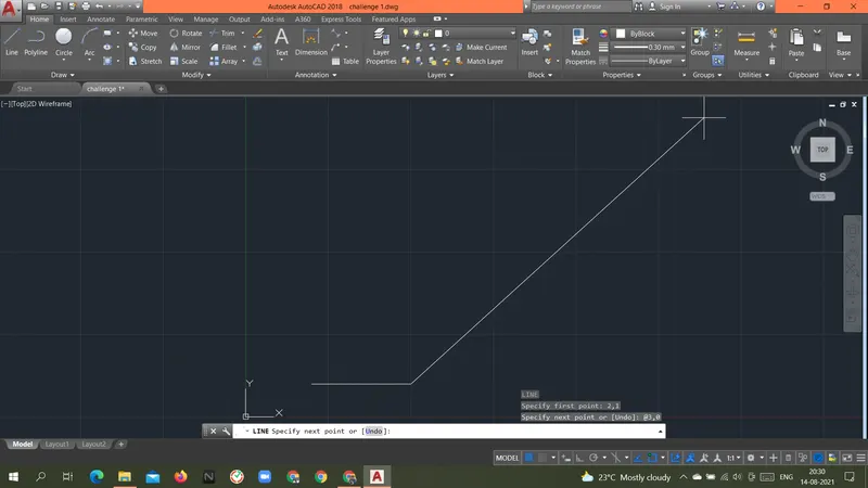
Specify next point or [Undo]: @0,4
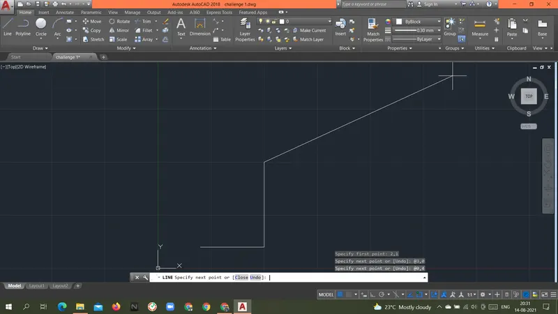
Specify next point or [Close/Undo]: @1,0
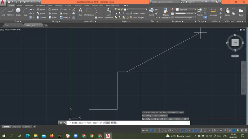
Specify next point or [Close/Undo]: @0,-4
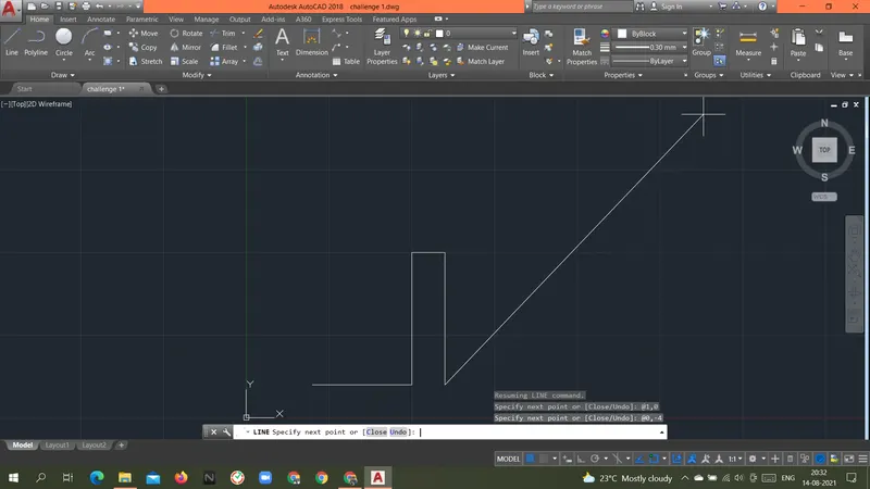
Specify next point or [Close/Undo]: @3,0
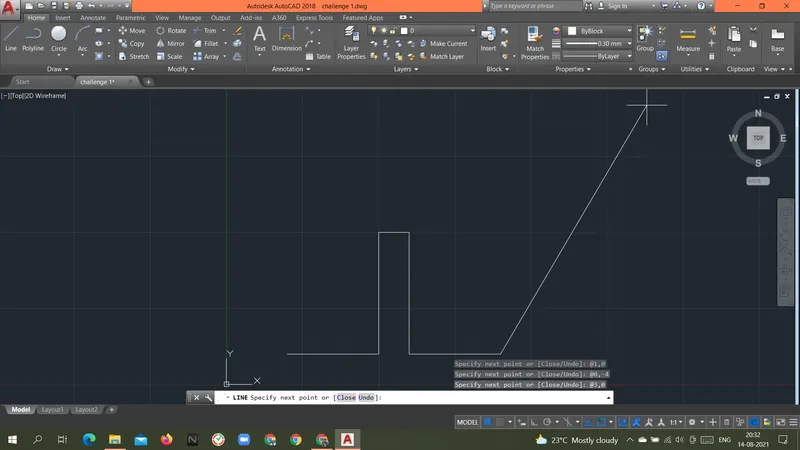
Specify next point or [Close/Undo]: @-2,7
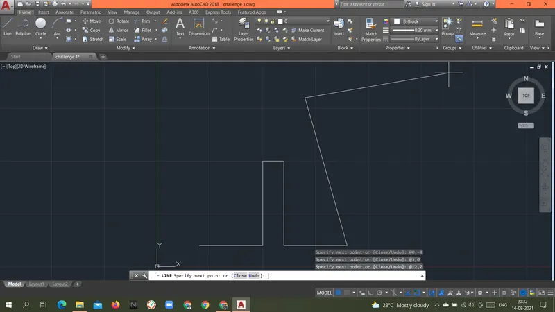
Specify next point or [Close/Undo]: @-3,0
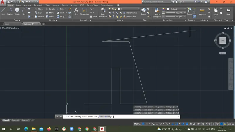
Specify next point or [Close/Undo]: @-2,-7
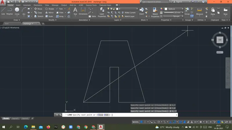
Specify next point or [Close/Undo]: c
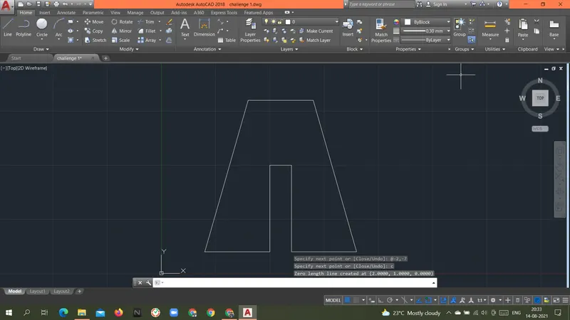
RESULT: Above geometry P2 was drawn with Relative rectangular coordinate system.
Relative Polar coordinate System
Procedure:
Command: L
LINE
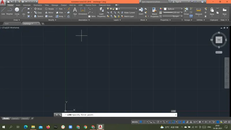
Specify first point: 2,1
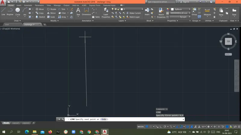
Specify next point or [Undo]: @3<0
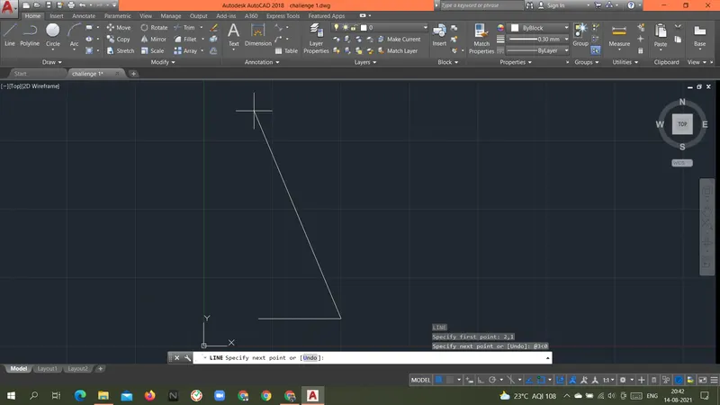
Specify next point or [Undo]: @4<90
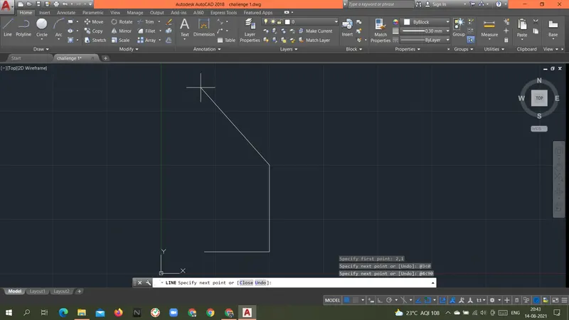
Specify next point or [Close/Undo]: @1<0
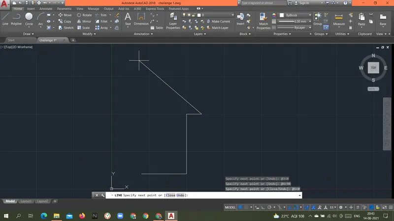
Specify next point or [Close/Undo]: @4<270
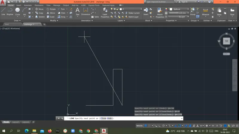
Specify next point or [Close/Undo]: @3<0
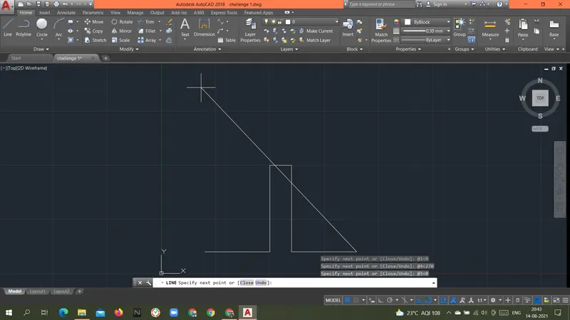
Specify next point or [Close/Undo]: @7.2801<106
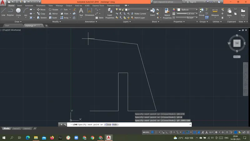
Specify next point or [Close/Undo]: @3<180
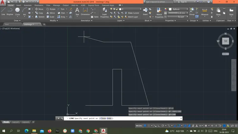
Specify next point or [Close/Undo]: @7.2801<254
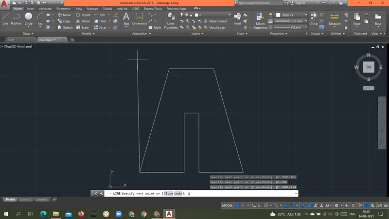
Specify next point or [Close/Undo]: c
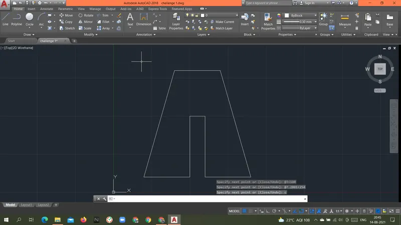
RESULT: Above geometry P2 was drawn with a Relative polar coordinate system.
Direct Distance Entry Method.
Command: L
LINE
Specify first point: 2,1
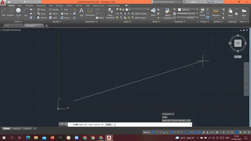
Specify next point or [Undo]: 3
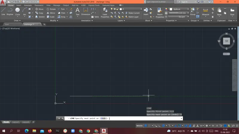
Specify next point or [Undo]: 4
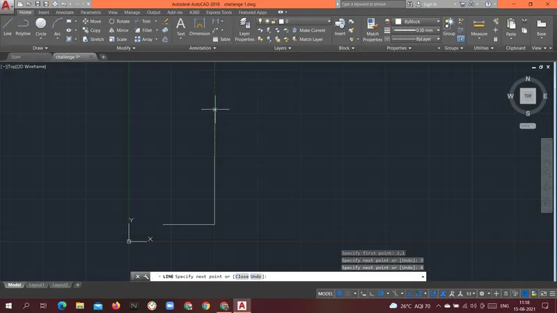
Specify next point or [Close/Undo]: 1
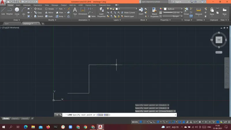
Specify next point or [Close/Undo]: 4
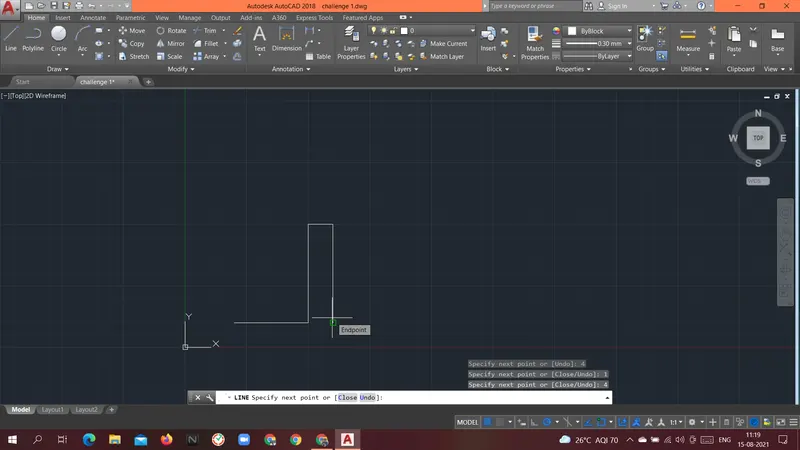
Specify next point or [Close/Undo]: 3
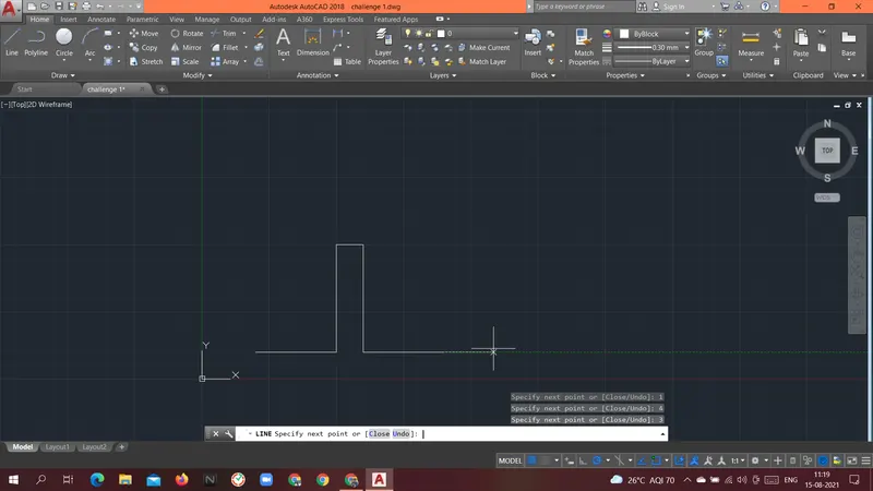
Specify next point or [Close/Undo]: 7.2801
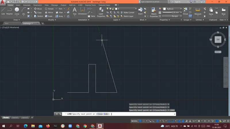
Specify next point or [Close/Undo]: 3
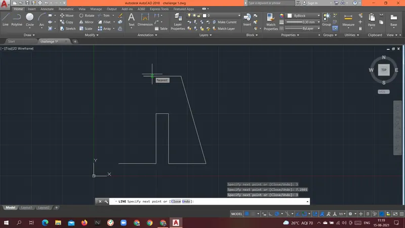
Specify next point or [Close/Undo]: 7.2801
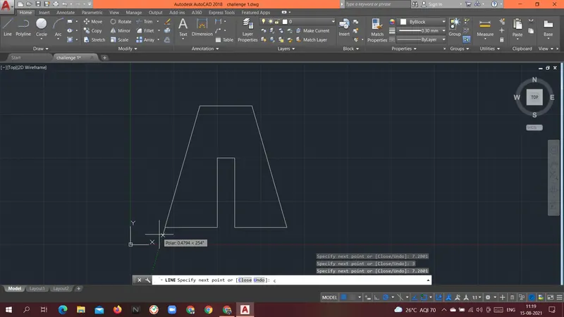
Specify next point or [Close/Undo]: c
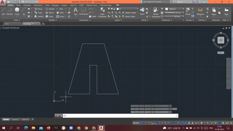
RESULT: Above geometry P2 was drawn with a Direct distance entry method.
----------------------------------------------------------------------------------------------------------------------------------------------------------------------------
Aim: To create the geometries of the P4 form above using different coordinates system methods.
Introduction: there are different types of coordinate systems that can be used.
- Absolute coordinate system.
- In this system, the absolute location of the point is given as an input.
- Always the origin(0,0) is the reference point for all the points in the geometry.
Procedure:
Command: L
LINE
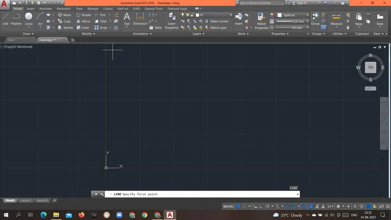
Specify first point: 2,1
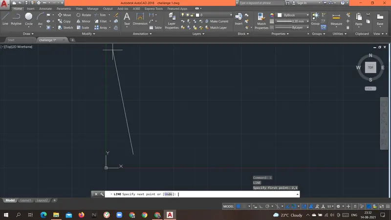
Specify next point or [Undo]: 3,1
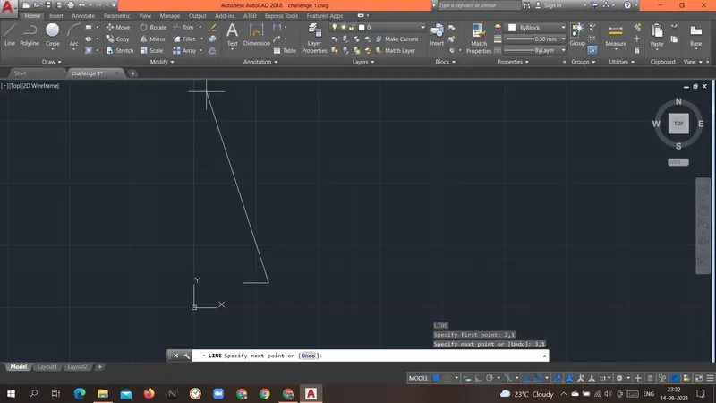
Specify next point or [Undo]: 3,5
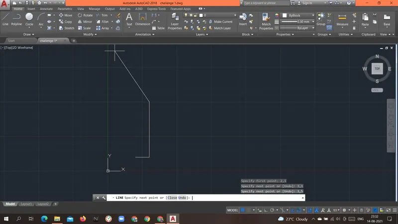
Specify next point or [Close/Undo]: 5,3
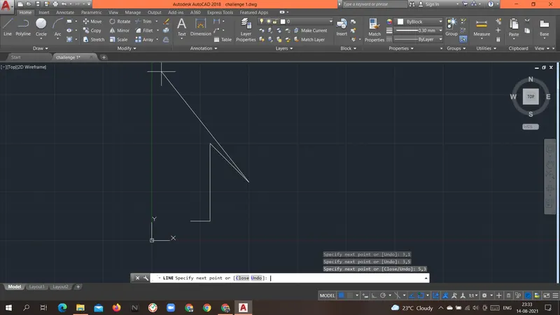
Specify next point or [Close/Undo]: 7,5
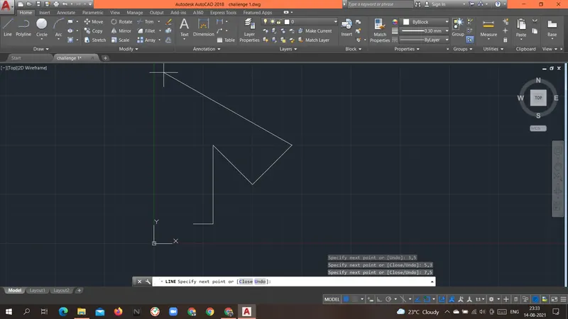
Specify next point or [Close/Undo]: 7,1
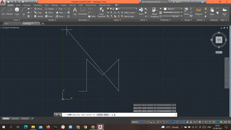
Specify next point or [Close/Undo]: 8,1
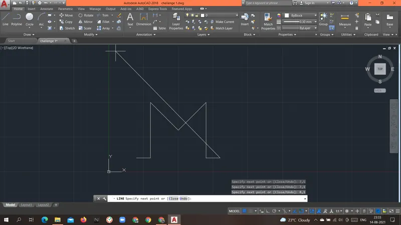
Specify next point or [Close/Undo]: 8,8
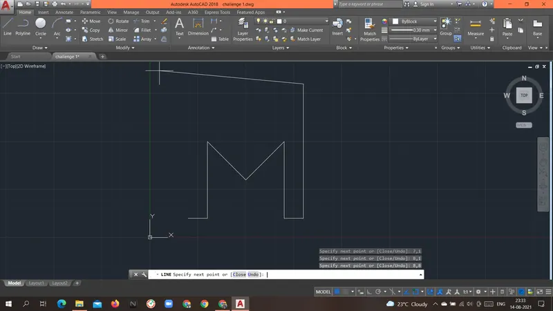
Specify next point or [Close/Undo]: 7,8
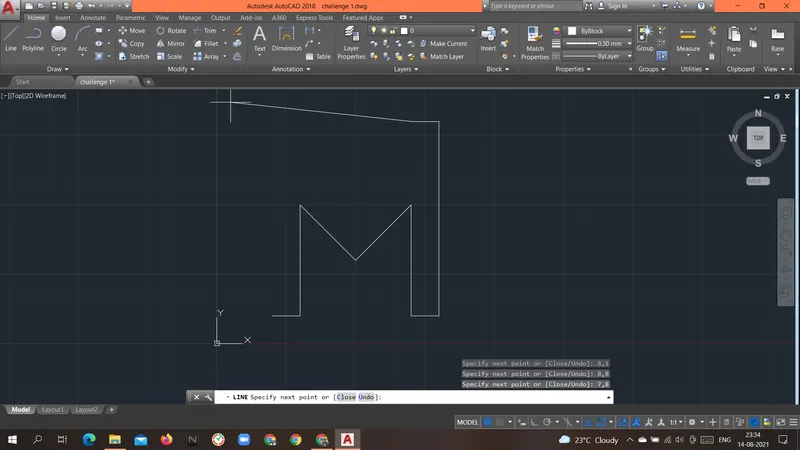
Specify next point or [Close/Undo]: 5,5
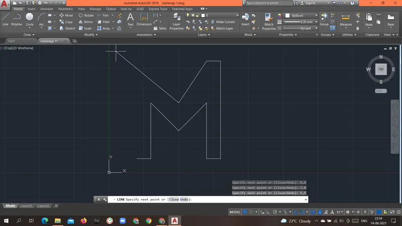
Specify next point or [Close/Undo]: 3,8
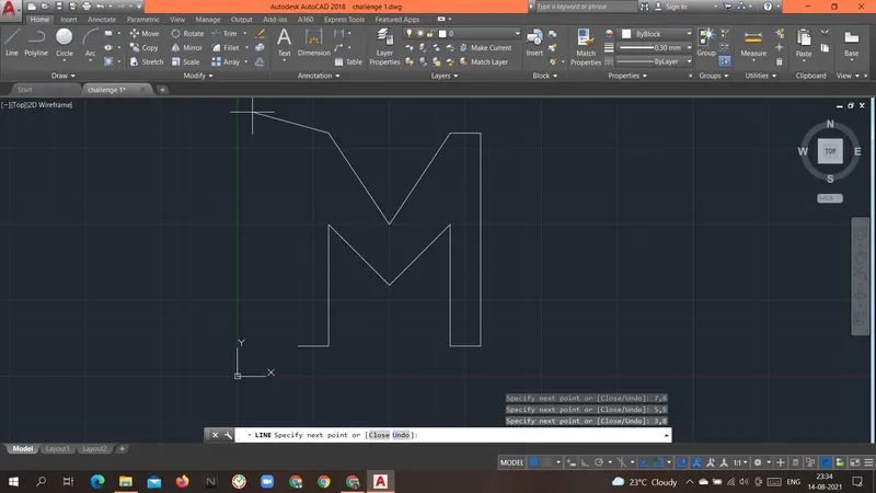
Specify next point or [Close/Undo]: 2,8
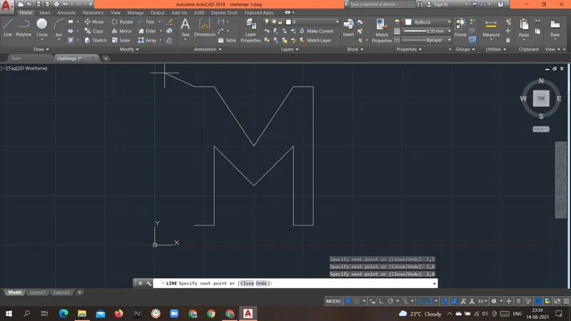
Specify next point or [Close/Undo]: 2,1
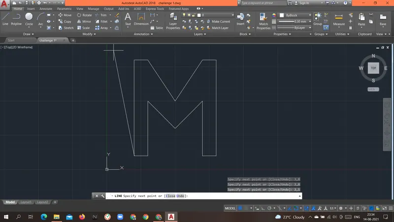
Specify next point or [Close/Undo]: c
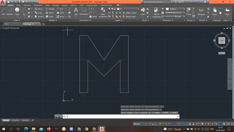
RESULT: Above geometry P4 was drawn with an Absolute coordinate system.
----------------------------------------------------------------------------------------------------------------------------------------------------------------------------
Aim: To create the geometries of the P-5 form above using different coordinates system methods.
Introduction: there are different types of coordinate systems that can be used.
- Absolute coordinate system.
- In this system, the absolute location of the point is given as an input.
- Always the origin(0,0) is the reference point for all the points in the geometry.
- Relative coordinates system.
- Relative rectangular coordinates system.
- This system is based on the previous location of the point.
- Once the first point is given the next point will take the previous point as a reference point.
- Taking the previous point as a reference point the coordinate of the next point is given.
- Relative polar coordinates system.
- In this coordinate system, the relative distance and angle are given with the previous point.
- angle is given with respect to the positive x-axis(by default).
- Relative rectangular coordinates system.
- Direct distance entry.
- In this coordinate system first, we provide the direction with the mouse and we have to input the distance.
Procedure:
Command: L
LINE
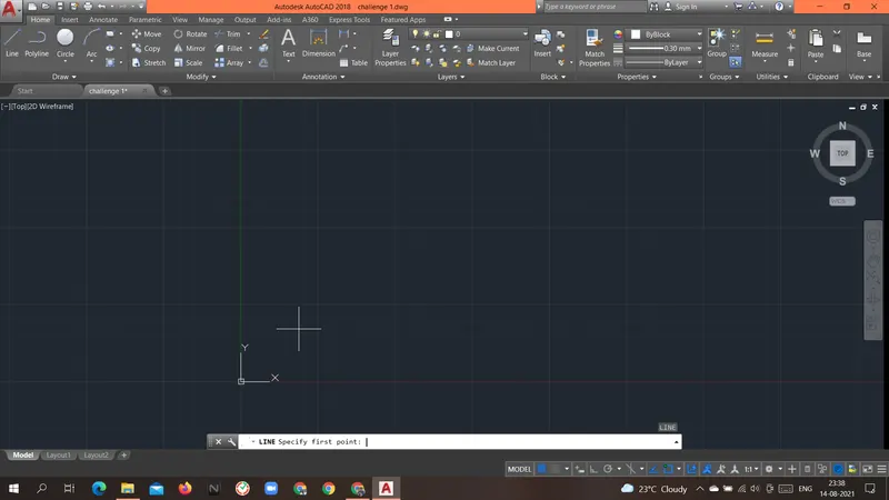
Specify first point: 2,1
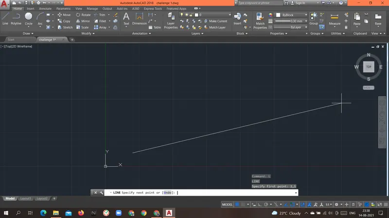
Specify next point or [Undo]: 3,1
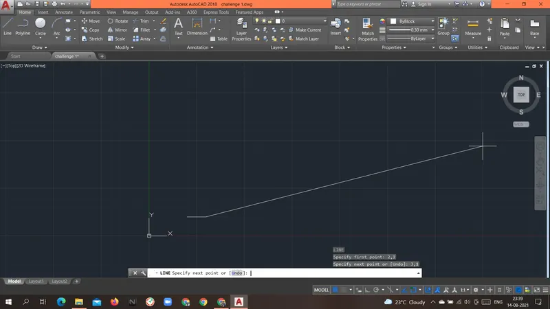
Specify next point or [Undo]: 3,8
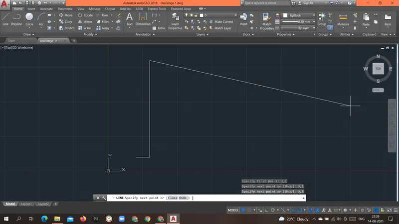
Specify next point or [Close/Undo]: 8,8
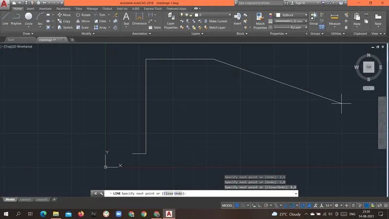
Specify next point or [Close/Undo]: 8,2
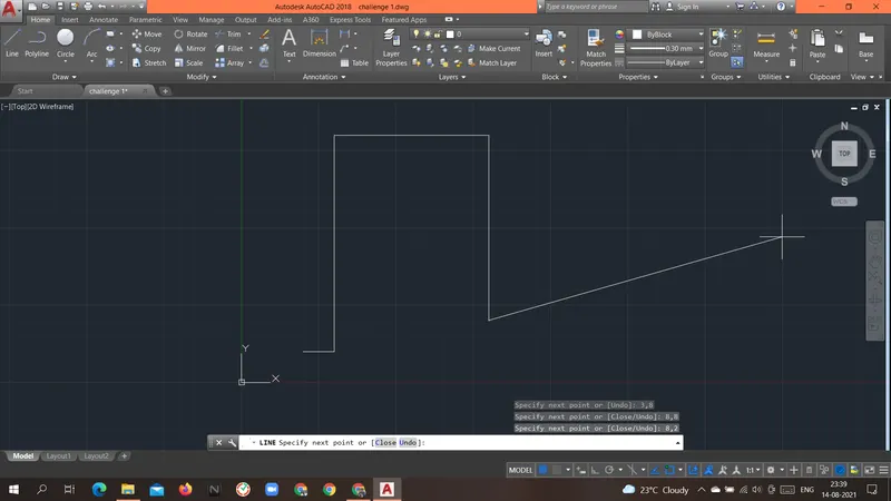
Specify next point or [Close/Undo]: 5,2
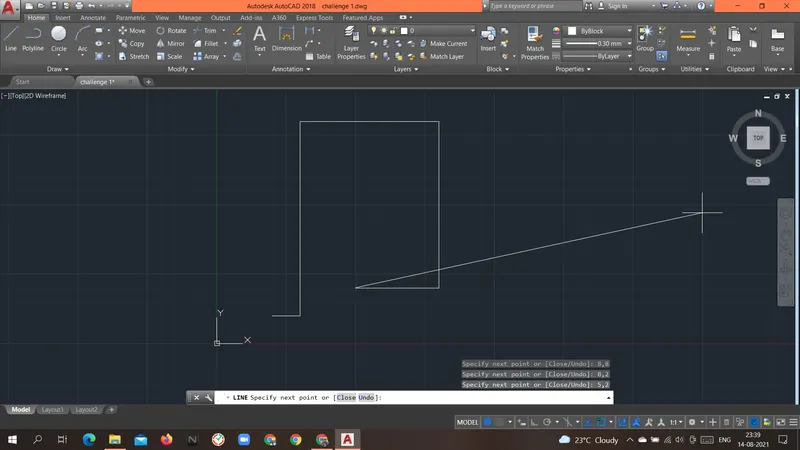
Specify next point or [Close/Undo]: 5,1
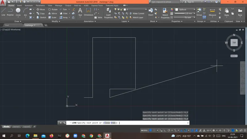
Specify next point or [Close/Undo]: 9,1
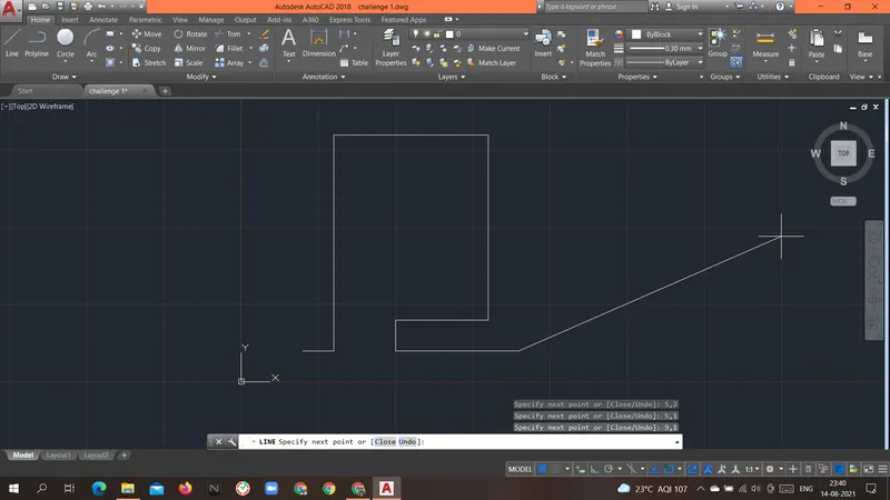
Specify next point or [Close/Undo]: 9,9
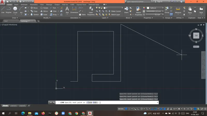
Specify next point or [Close/Undo]: 2,9
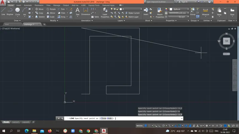
Specify next point or [Close/Undo]: 2,1
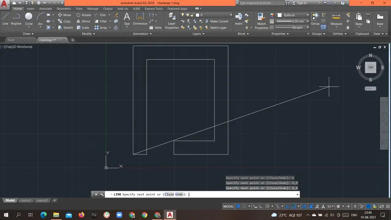
Specify next point or [Close/Undo]: c
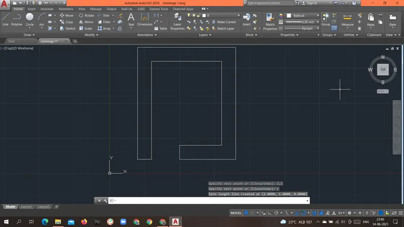
Result: Above geometry P-5 was drawn with an Absolute coordinate system.
----------------------------------------------------------------------------------------------------------------------------------------------------------------------------
Aim: To create the geometries of the P-7 form above using different coordinates system methods.
Introduction: there are different types of coordinate systems that can be used.
- Absolute coordinate system.
- In this system, the absolute location of the point is given as an input.
- Always the origin(0,0) is the reference point for all the points in the geometry.
Procedure:
Command: L
LINE
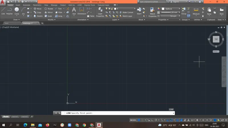
Specify first point: 2,1
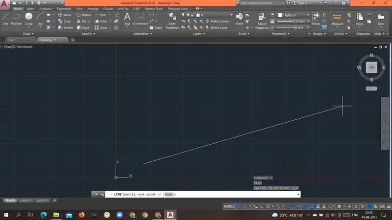
Specify next point or [Undo]: 10,1
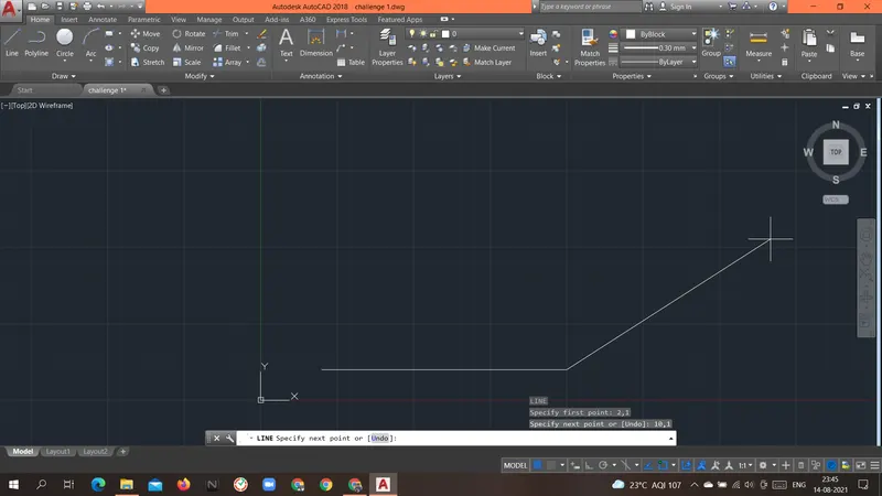
Specify next point or [Undo]: 10,7
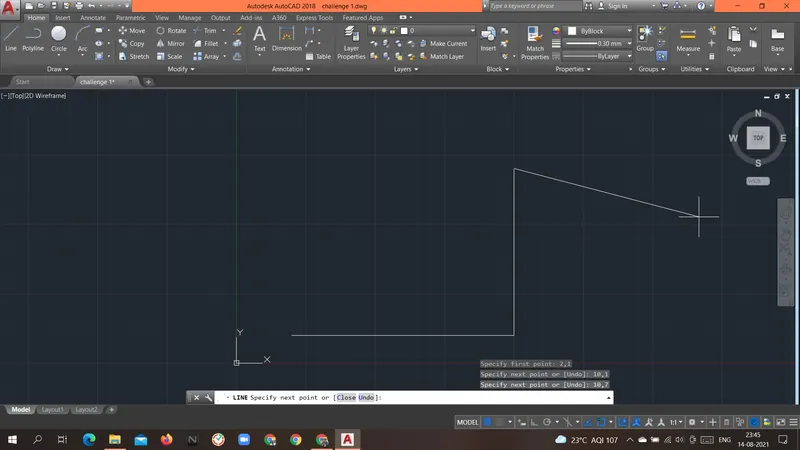
Specify next point or [Close/Undo]: 2,7
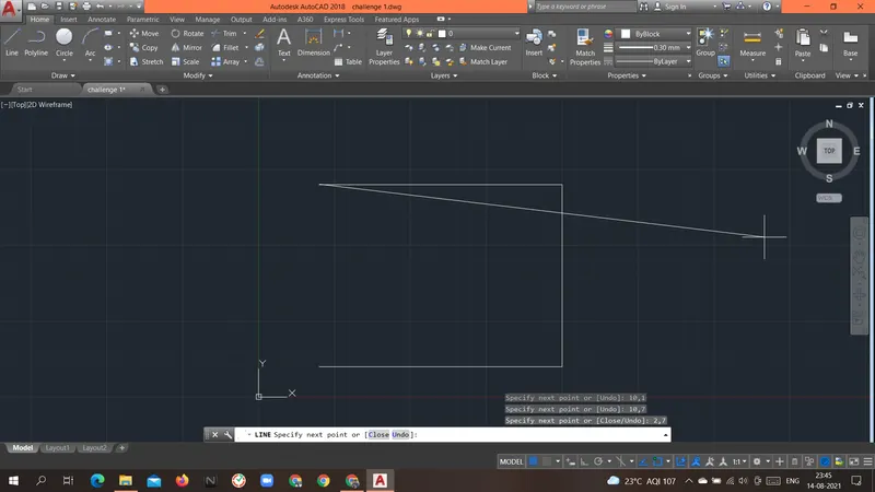
Specify next point or [Close/Undo]: 2,1
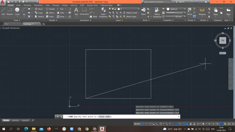
Specify next point or [Close/Undo]: c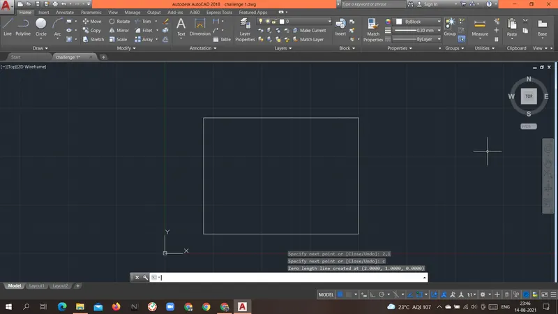
Command: L
LINE
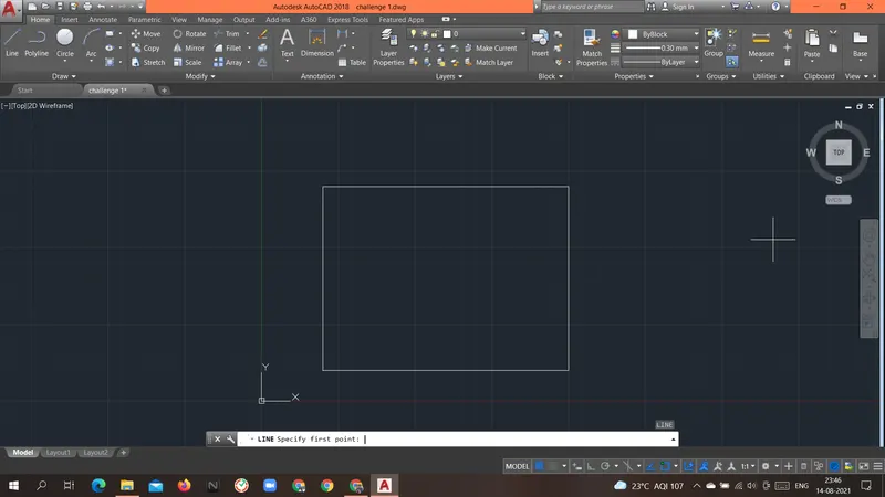
Specify first point: 3,2
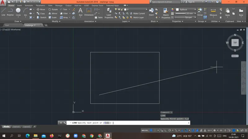
Specify next point or [Undo]: 5,2
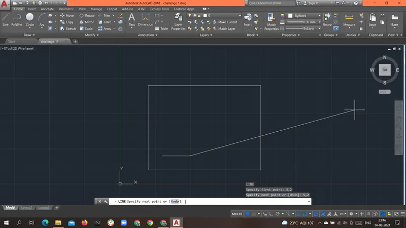
Specify next point or [Undo]: 5,5
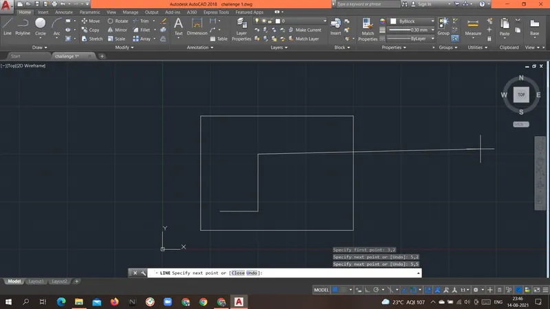
Specify next point or [Close/Undo]: 3,5
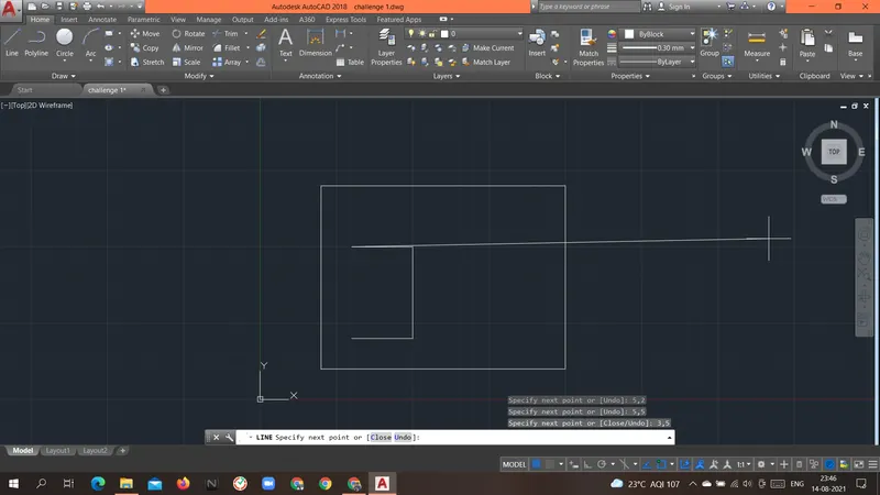
Specify next point or [Close/Undo]: 3,2
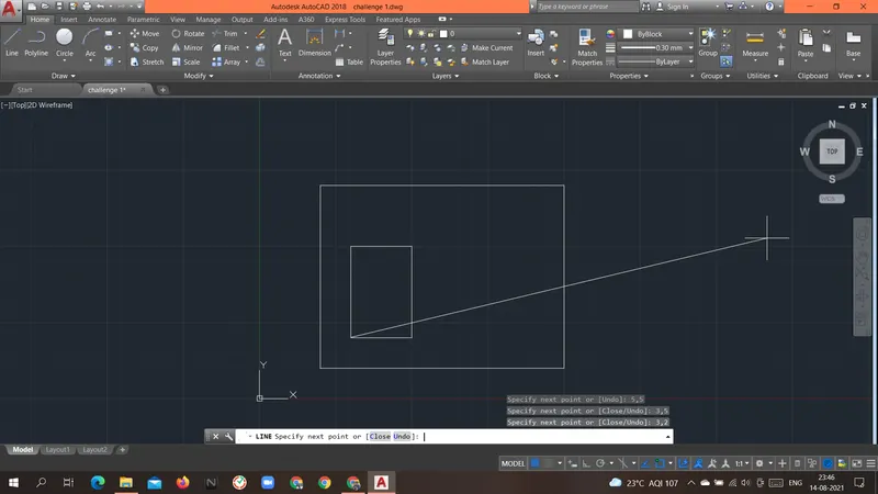
Specify next point or [Close/Undo]: c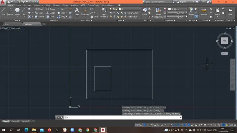
Command: L
LINE
Specify first point: 6,2
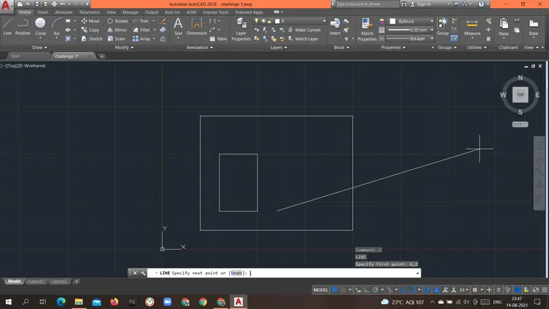
Specify next point or [Undo]: 8,2
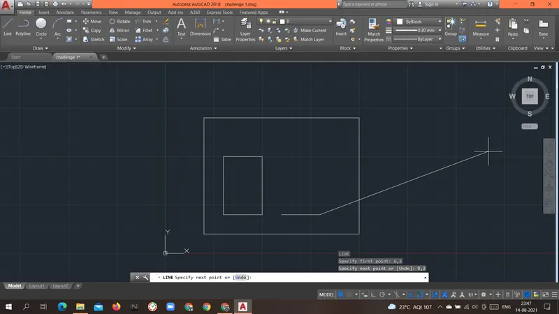
Specify next point or [Undo]: 8,5
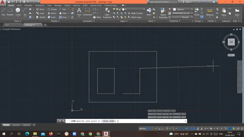
Specify next point or [Close/Undo]: 6,5
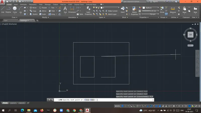
Specify next point or [Close/Undo]: 6,2
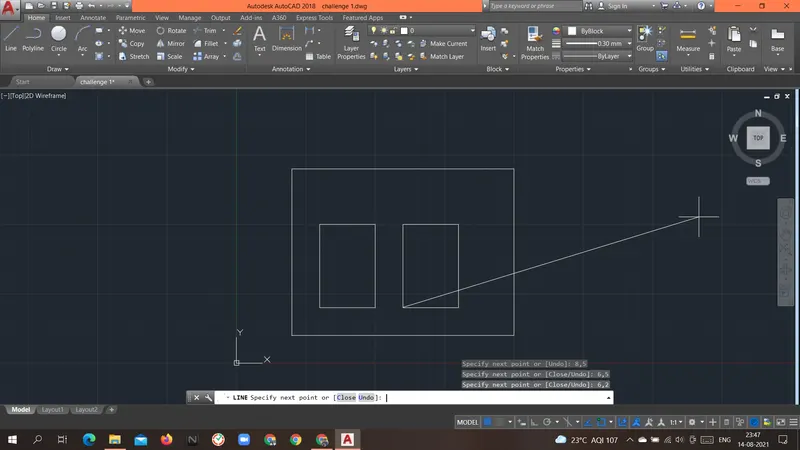
Specify next point or [Close/Undo]: c
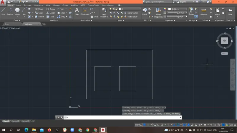
Result: Above geometry P-7 was drawn with an Absolute coordinate system.
----------------------------------------------------------------------------------------------------------------------------------------------------------------------------
Aim: To create the geometries of the P-8 form above using different coordinates system methods.
Introduction: there are different types of coordinate systems that can be used.
- Absolute coordinate system.
- In this system, the absolute location of the point is given as an input.
- Always the origin(0,0) is the reference point for all the points in the geometry.
Procedure:
Command: L
LINE
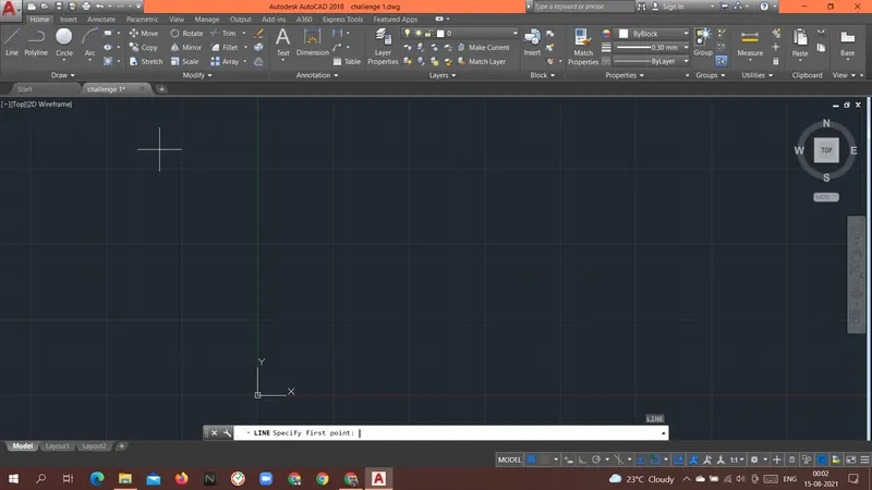
Specify first point: 0,0
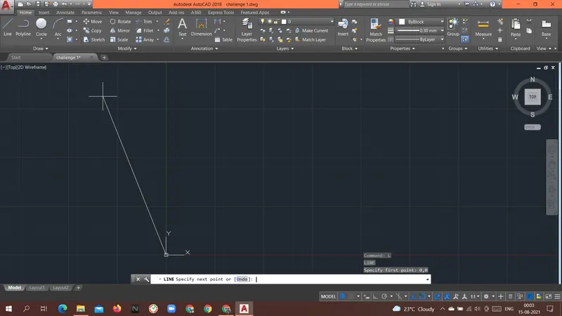
Specify next point or [Undo]: 10,0
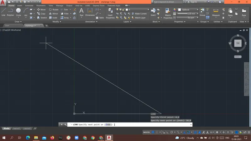
Specify next point or [Undo]: 10,2
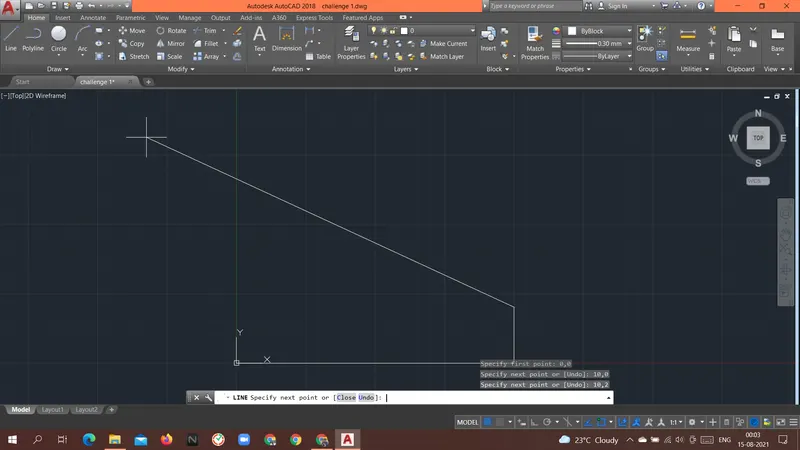
Specify next point or [Close/Undo]: 6,2
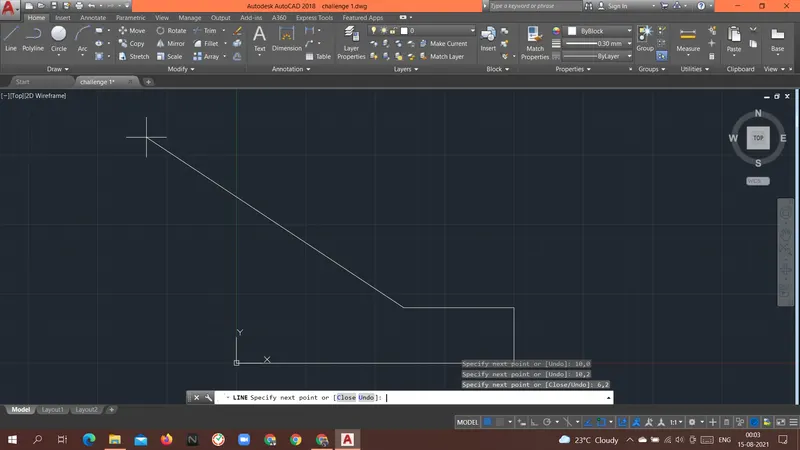
Specify next point or [Close/Undo]: 6,6
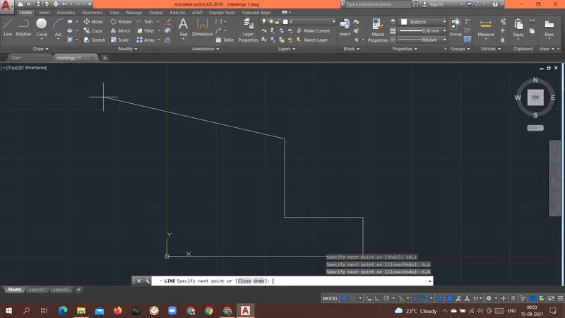
Specify next point or [Close/Undo]: 9,6
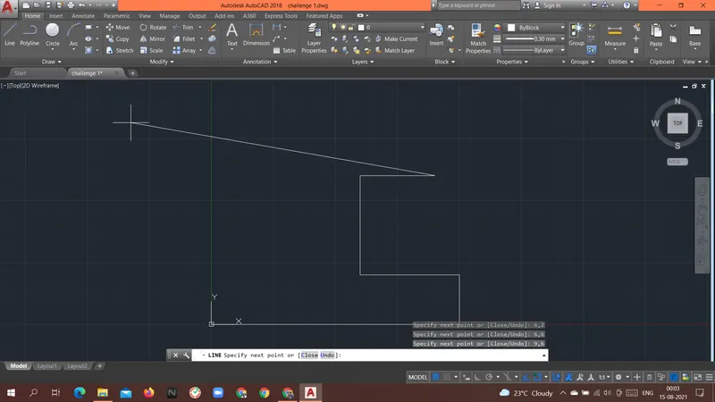
Specify next point or [Close/Undo]: 9,8
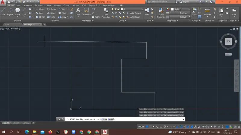
Specify next point or [Close/Undo]: 1,8
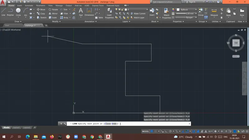
Specify next point or [Close/Undo]: 1,6
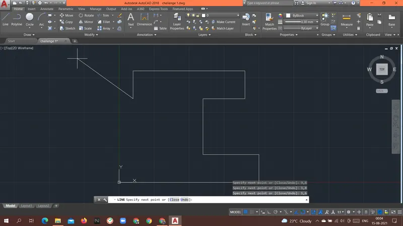
Specify next point or [Close/Undo]: 4,6
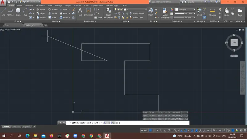
Specify next point or [Close/Undo]: 4,2
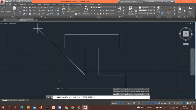
Specify next point or [Close/Undo]: 0,2
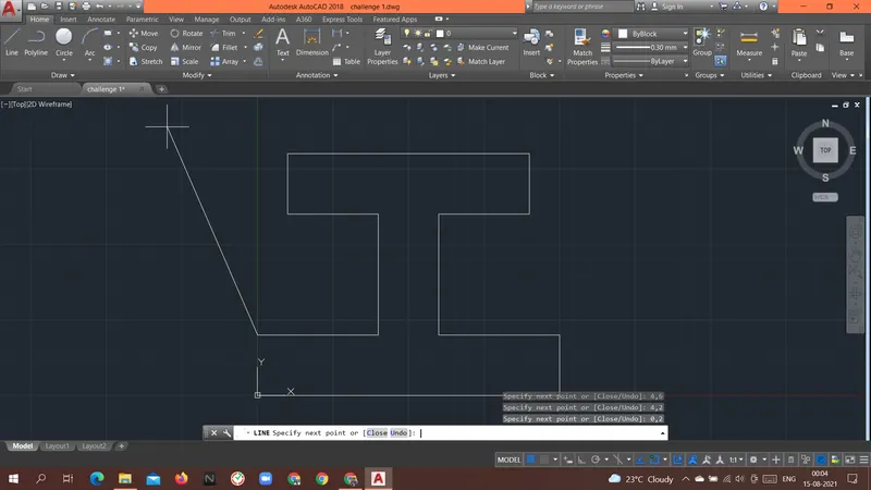
Specify next point or [Close/Undo]: 0,0
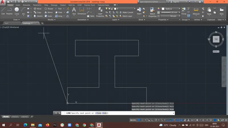
Specify next point or [Close/Undo]: c
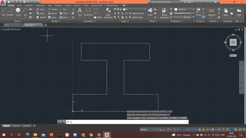
Result: Above geometry P-8 was drawn with an Absolute coordinate system.
----------------------------------------------------------------------------------------------------------------------------------------------------------------------------
Aim: To create the geometries of the P-9 form above using different coordinates system methods.
Introduction: there are different types of coordinate systems that can be used.Relative coordinates system.
- Relative rectangular coordinates system.
- This system is based on the previous location of the point.
- Once the first point is given the next point will take the previous point as a reference point.
- Taking the previous point as a reference point the coordinate of the next point is given.
Procedure:
Command: L
LINE
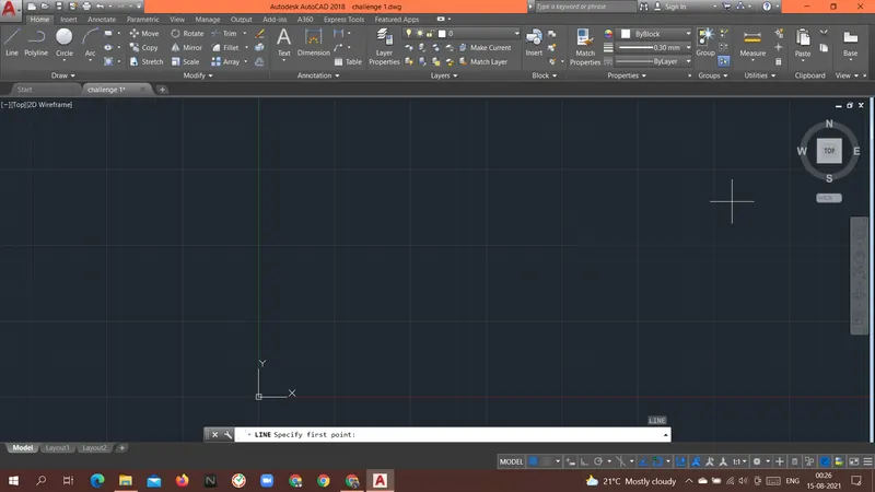
Specify first point: 1,1
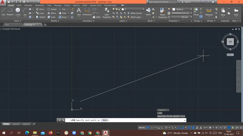
Specify next point or [Undo]: @5,0
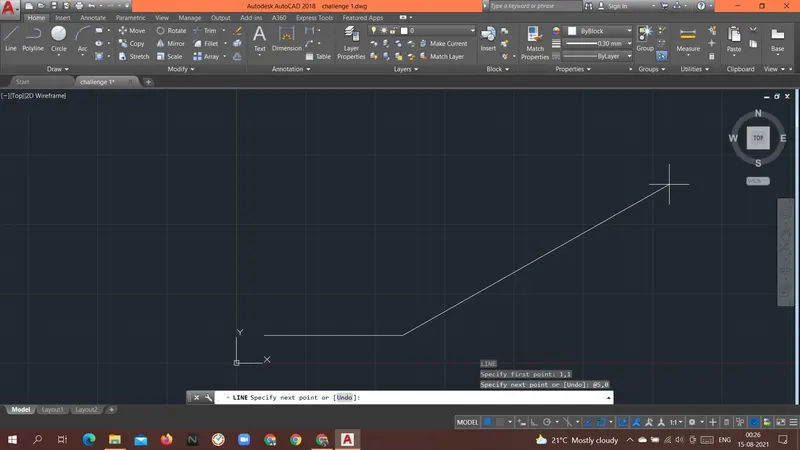
Specify next point or [Undo]: @0,2
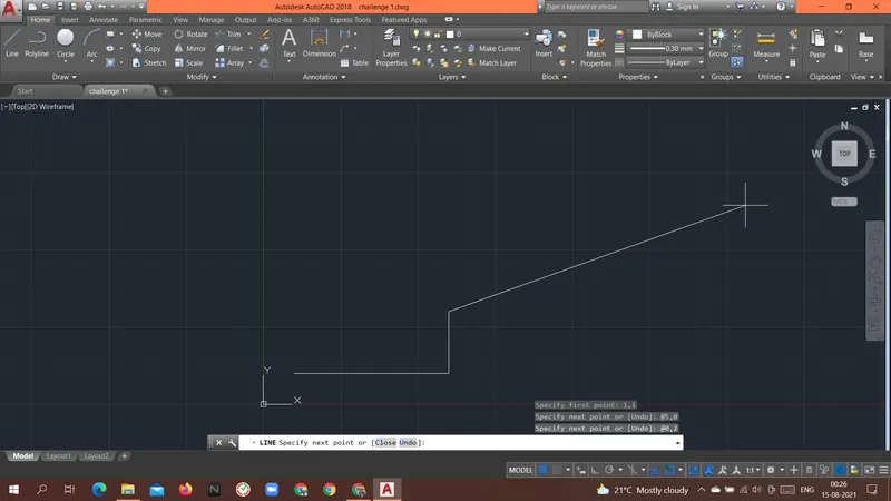
Specify next point or [Close/Undo]: @-3,0
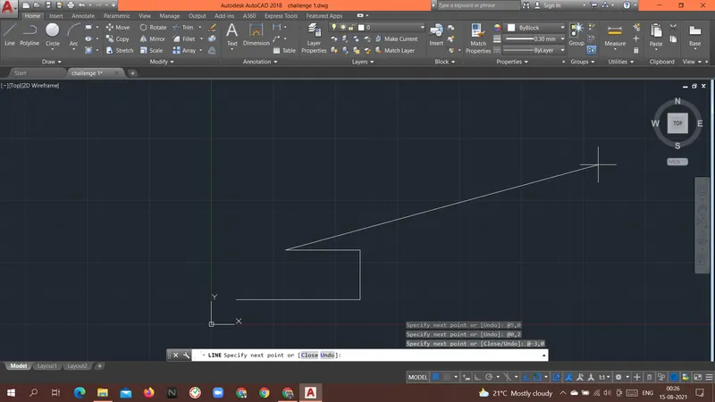
Specify next point or [Close/Undo]: @0,-1
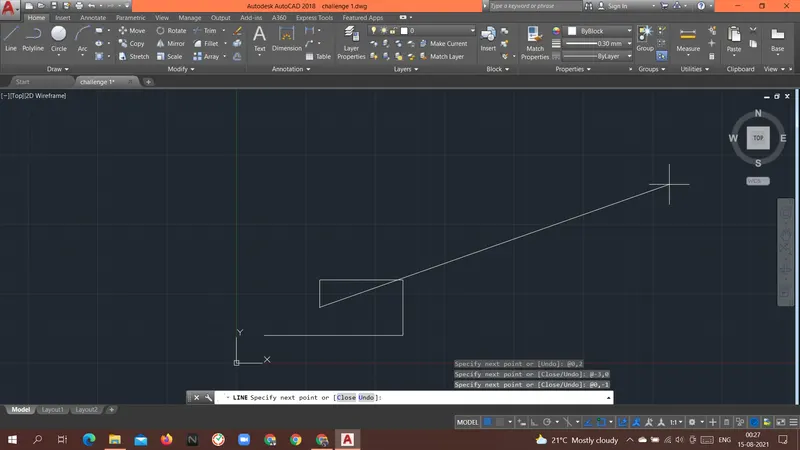
Specify next point or [Close/Undo]: @-1,0
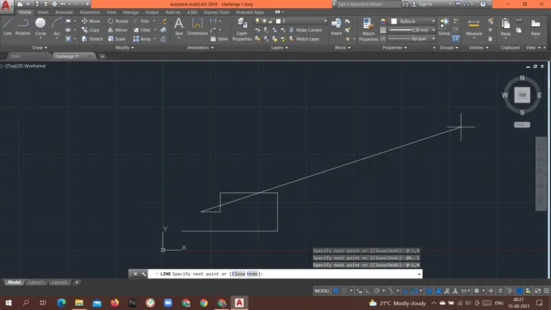
Specify next point or [Close/Undo]: @0,2
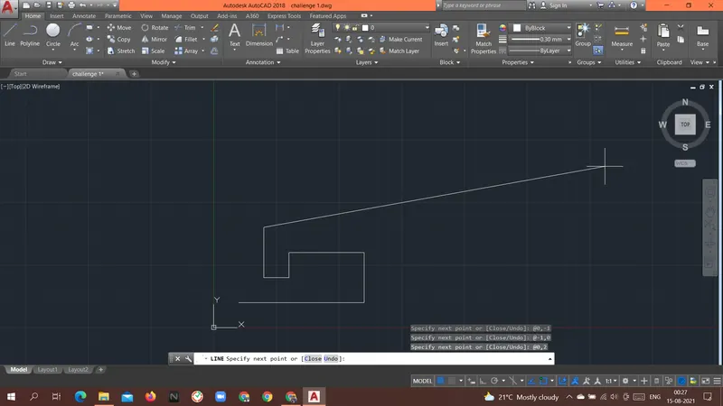
Specify next point or [Close/Undo]: @3,0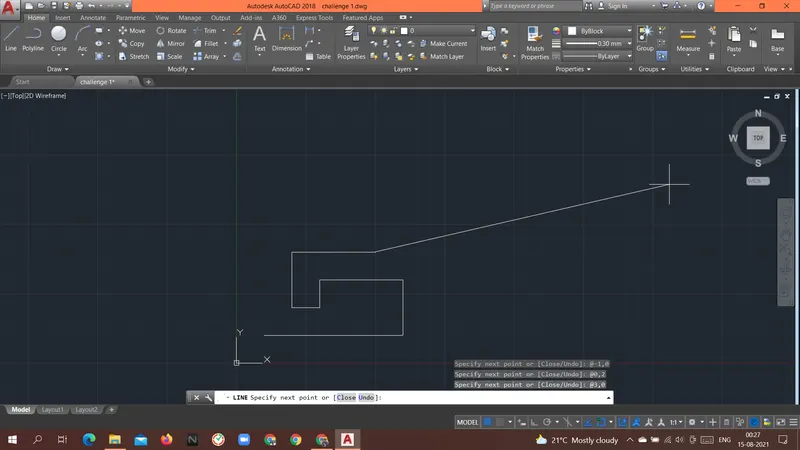
Specify next point or [Close/Undo]: @0,2
Specify next point or [Close/Undo]: @-4,2
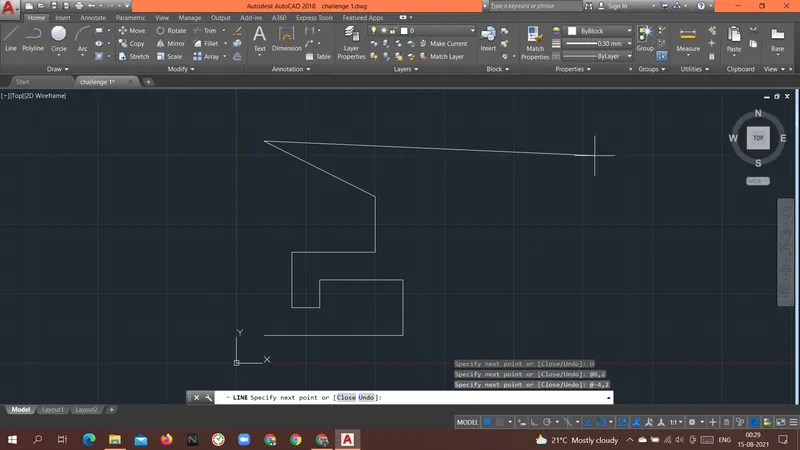
Specify next point or [Close/Undo]: @0,-7
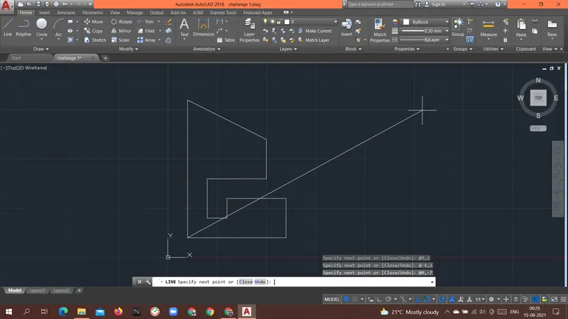
Specify next point or [Close/Undo]: c
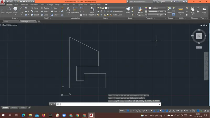
Result: Above geometry P-9 was drawn with a Relative rectangular coordinate system.
----------------------------------------------------------------------------------------------------------------------------------------------------------------------------
Aim: To create the geometries of the P-10 form above using different coordinates system methods.
Introduction: there are different types of coordinate systems that can be used.
-
- Relative rectangular coordinates system.
- This system is based on the previous location of the point.
- Once the first point is given the next point will take the previous point as a reference point.
- Taking the previous point as a reference point the coordinate of the next point is given.
- Relative rectangular coordinates system.
Procedure:
Command: L
LINE
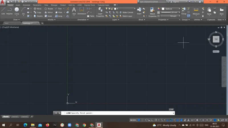
Specify first point: 1,1
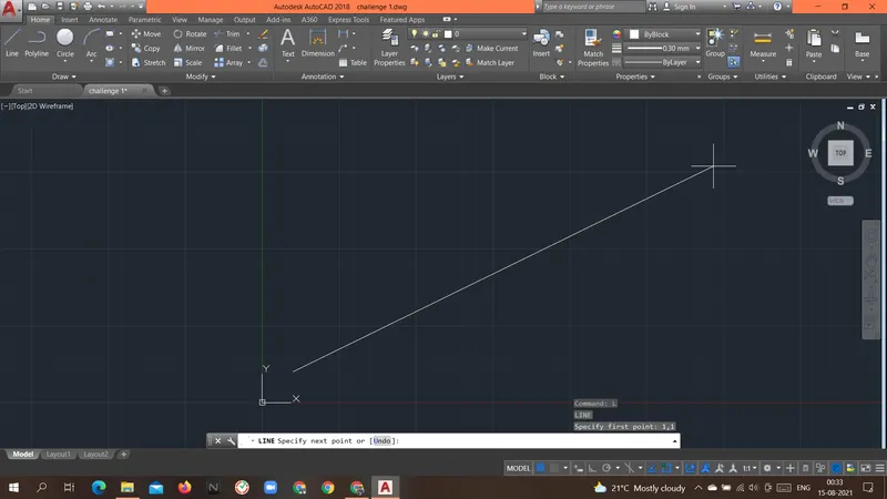
Specify next point or [Undo]: @2,0
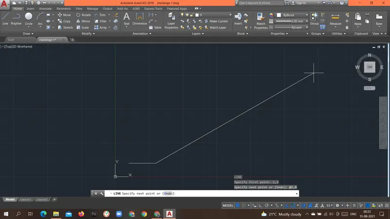
Specify next point or [Undo]: @0,3
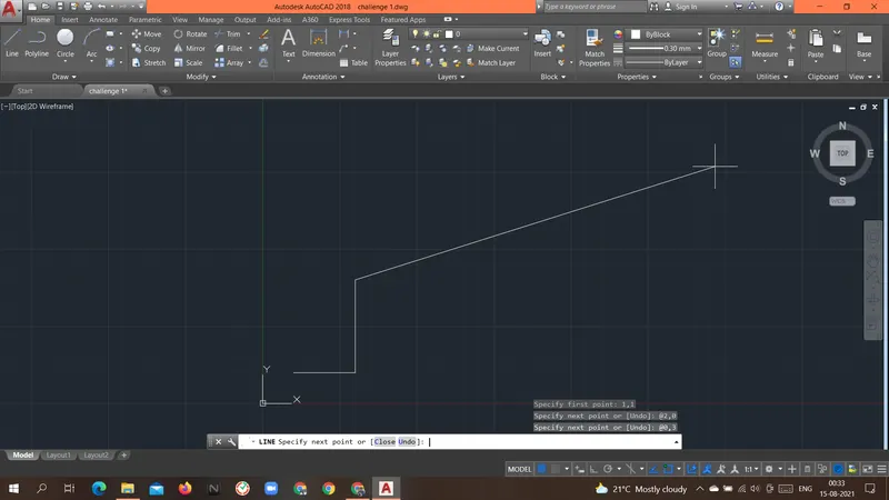
Specify next point or [Close/Undo]: @3,0
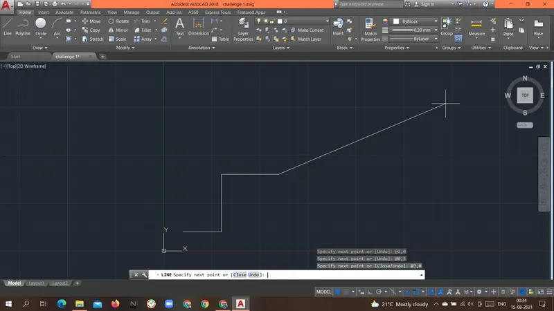
Specify next point or [Close/Undo]: @0,4
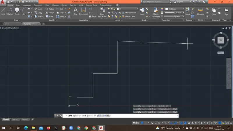
Specify next point or [Close/Undo]: @-5,0
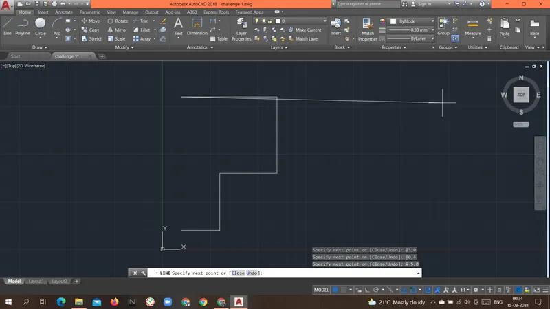
Specify next point or [Close/Undo]: @0,-7
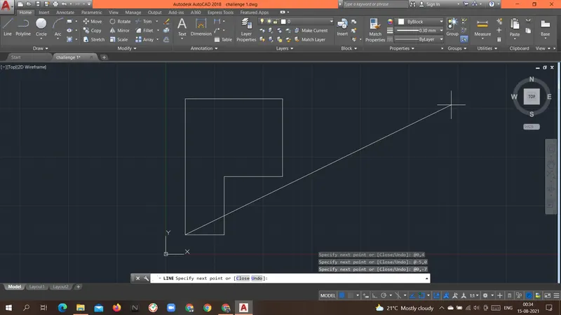
Specify next point or [Close/Undo]: c
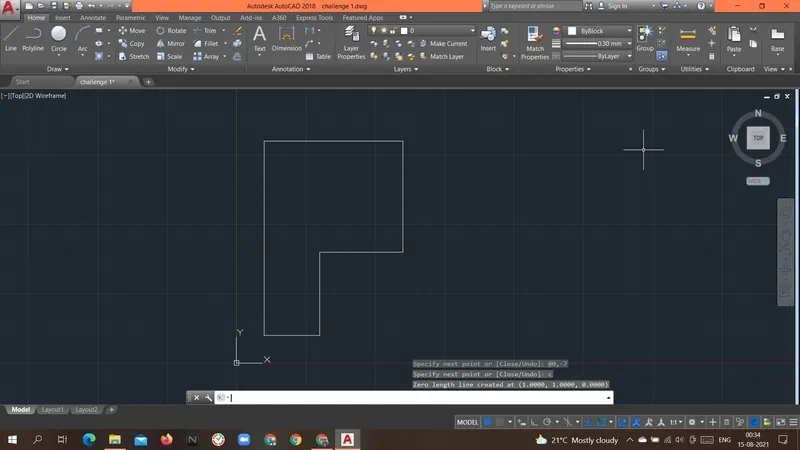
Command: L
LINE
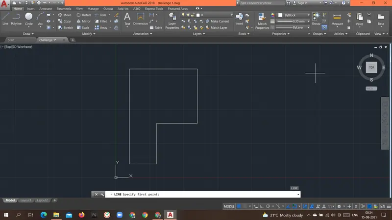
Specify first point: 2,5
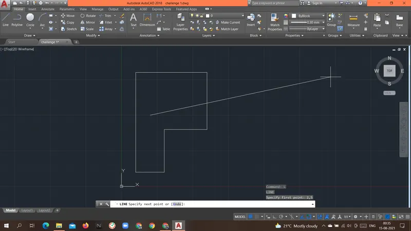
Specify next point or [Undo]: @3,0
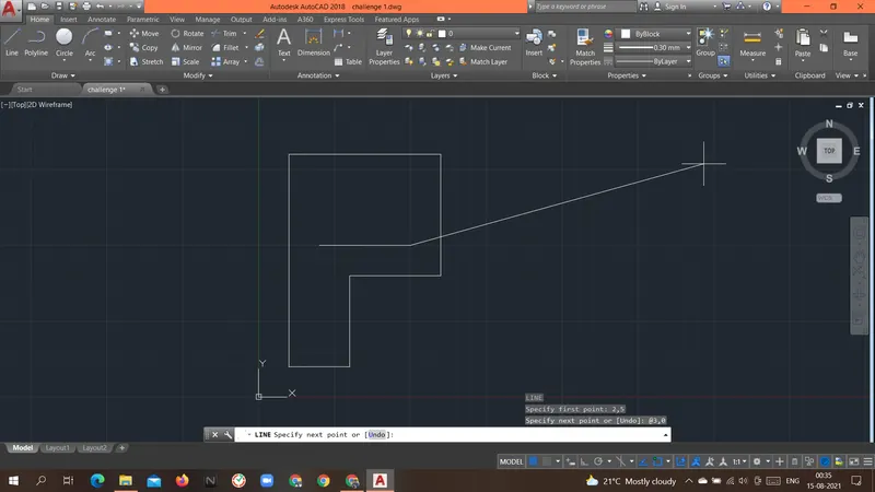
Specify next point or [Undo]: @0,2
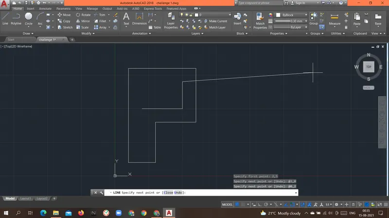
Specify next point or [Close/Undo]: @-3,0
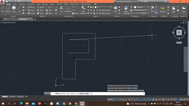
Specify next point or [Close/Undo]: @0,-2
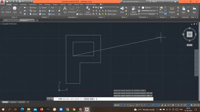
Specify next point or [Close/Undo]: c
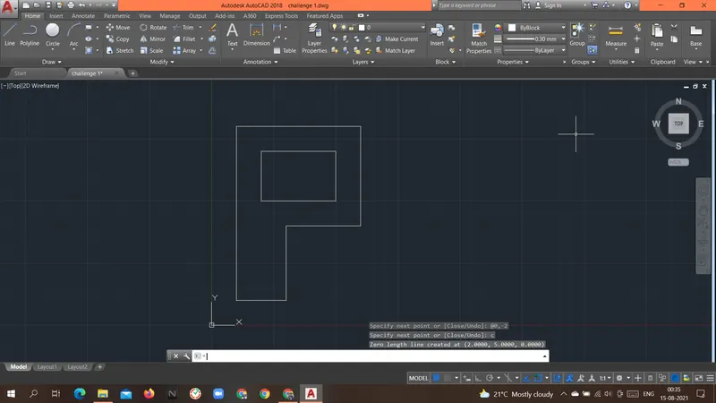
Result: Above geometry P-10 was drawn with a Relative rectangular coordinate system.
----------------------------------------------------------------------------------------------------------------------------------------------------------------------------
Aim: To create the geometries of the PROFILE WOOD form above using different coordinates system methods.
Introduction: there are different types of coordinate systems that can be used.
- Relative rectangular coordinates system.
- This system is based on the previous location of the point.
- Once the first point is given the next point will take the previous point as a reference point.
- Taking the previous point as a reference point the coordinate of the next point is given.
Procedure:
Command: L
LINE
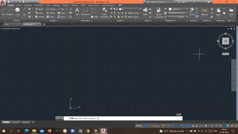
Specify first point: 0,0
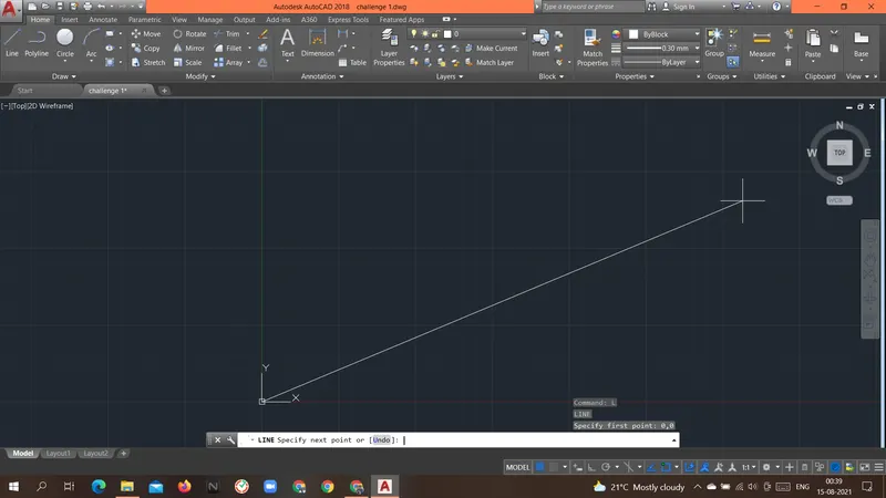
Specify next point or [Undo]: @10,0
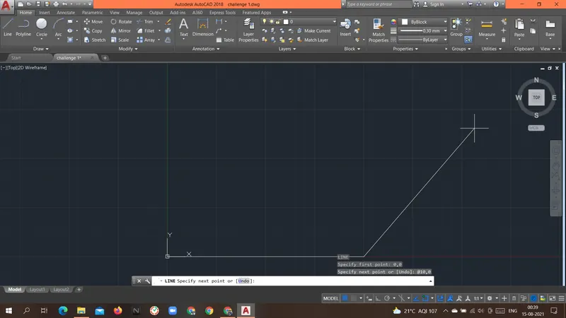
Specify next point or [Undo]: @0,1
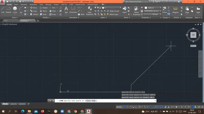
Specify next point or [Close/Undo]: @-2,0
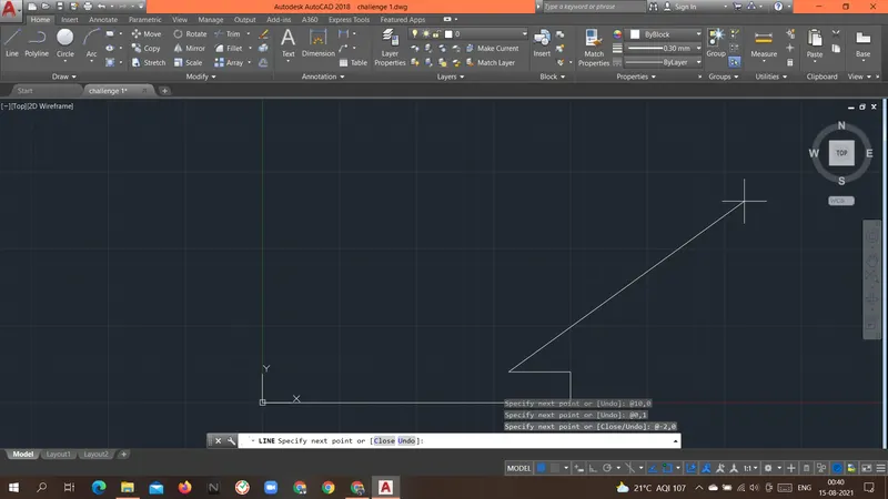
Specify next point or [Close/Undo]: @0,4
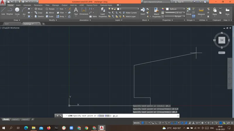
Specify next point or [Close/Undo]: @2,0
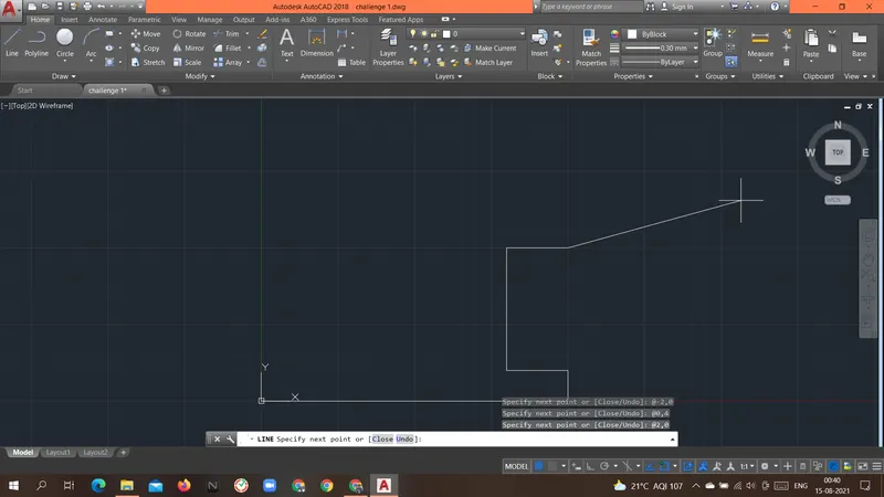
Specify next point or [Close/Undo]: @0,1
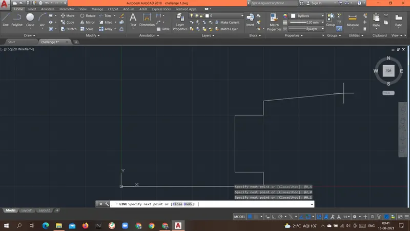
Specify next point or [Close/Undo]: @-5,3
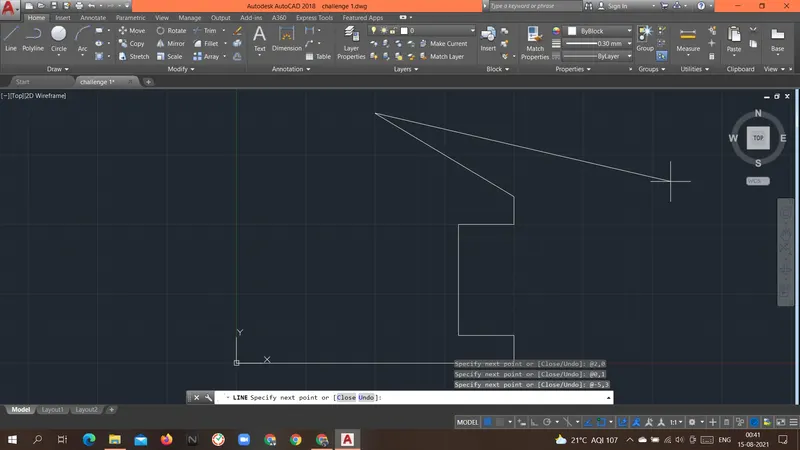
Specify next point or [Close/Undo]: @-5,-3
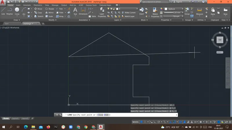
Specify next point or [Close/Undo]: @2,0
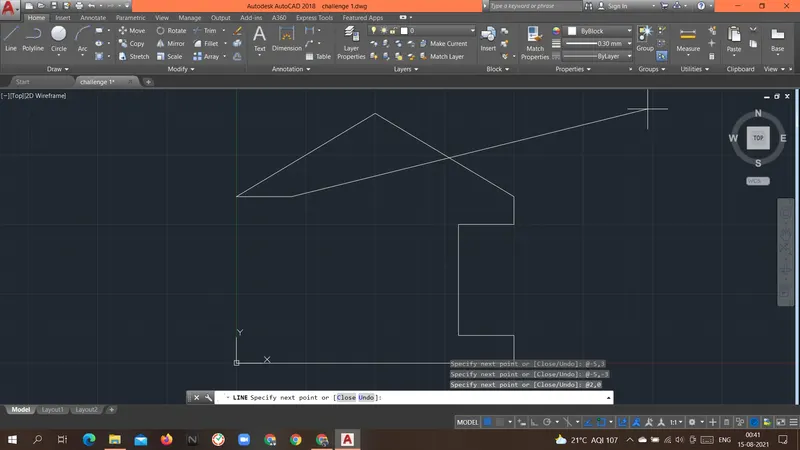
Specify next point or [Close/Undo]: @0,-5
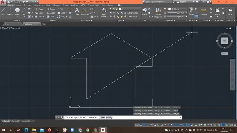
Specify next point or [Close/Undo]: @-2,0
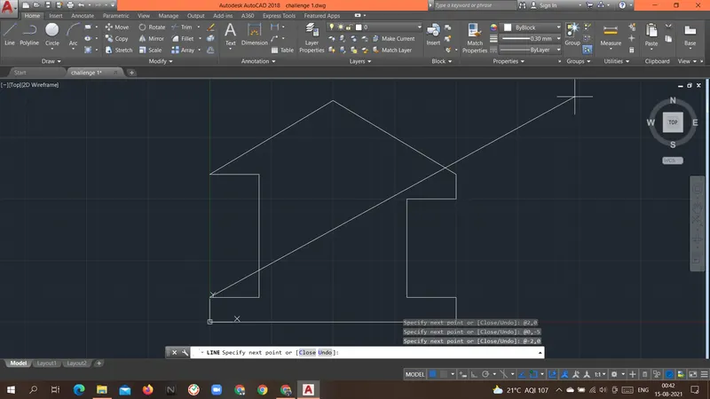
Specify next point or [Close/Undo]: @0,-1
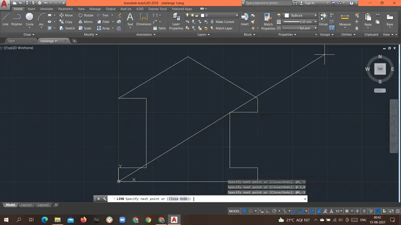
Specify next point or [Close/Undo]: c
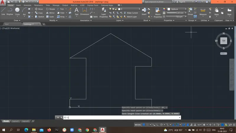
Command: C
CIRCLE
Specify center point for circle or [3P/2P/Ttr (tan tan radius)]: 5,4
Specify radius of circle or [Diameter]: 2
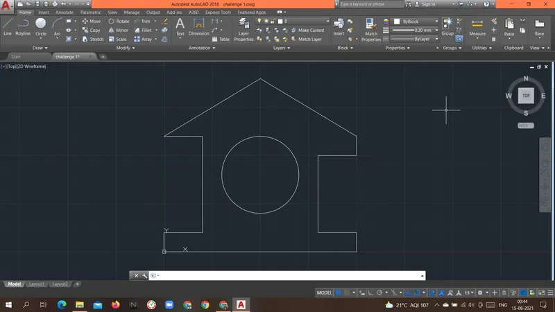
Result: Above geometry PROFILE WOOD was drawn with a Relative rectangular coordinate system.
----------------------------------------------------------------------------------------------------------------------------------------------------------------------------
Aim: To create the geometries of the MONO PITCH form above using different coordinates system methods.
Introduction: there are different types of coordinate systems that can be used.
- Absolute coordinate system.
- In this system, the absolute location of the point is given as an input.
- Always the origin(0,0) is the reference point for all the points in the geometry.
Procedure:
Command: L
LINE
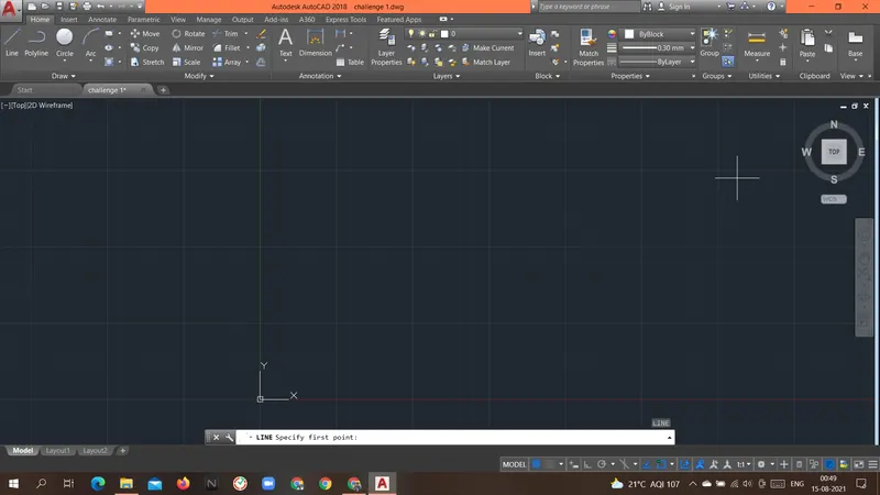
Specify first point: 1,1
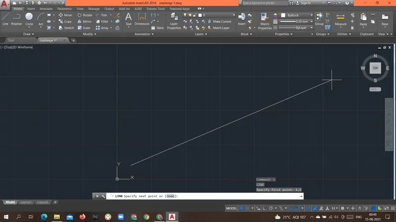
Specify next point or [Undo]: 7,1
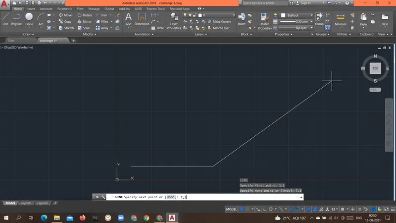
Specify next point or [Undo]: 7,3
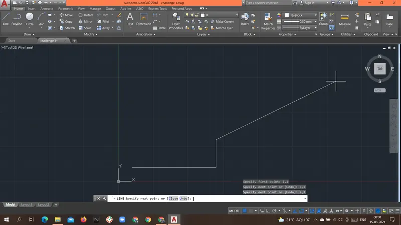
Specify next point or [Close/Undo]: 1,1
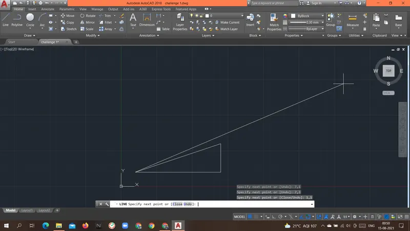
Specify next point or [Close/Undo]: c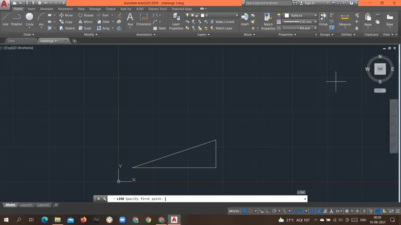
Command: L
LINE
Specify first point: 3,1
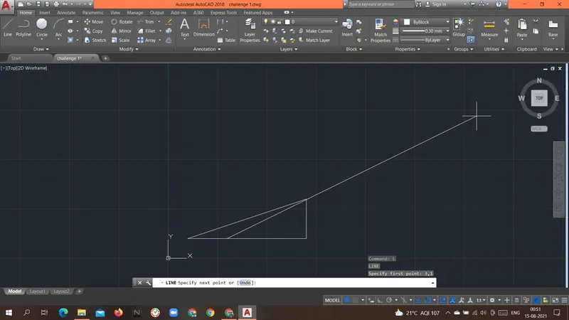
Specify next point or [Undo]: 3,1.667
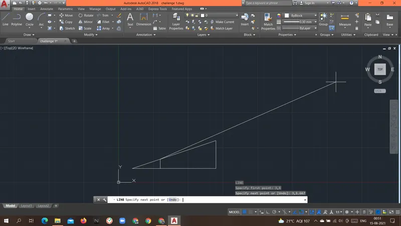
Specify next point or [Undo]: 5,1
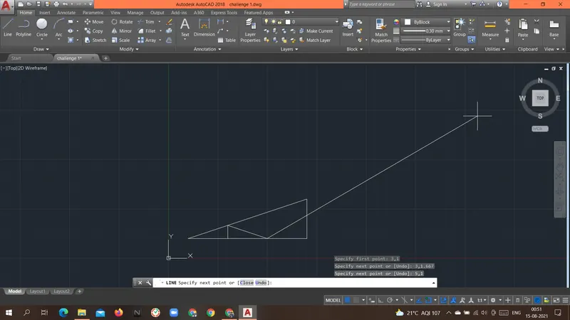
Specify next point or [Close/Undo]: 5,2.333
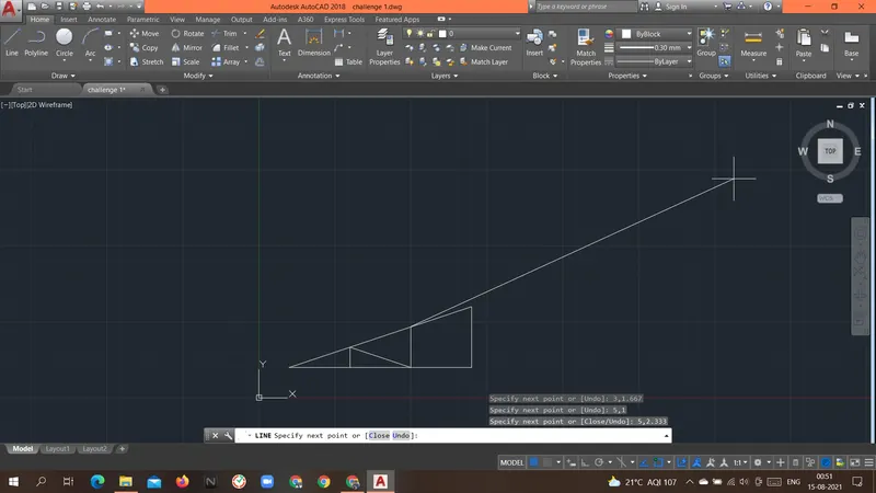
Specify next point or [Close/Undo]: 7,1
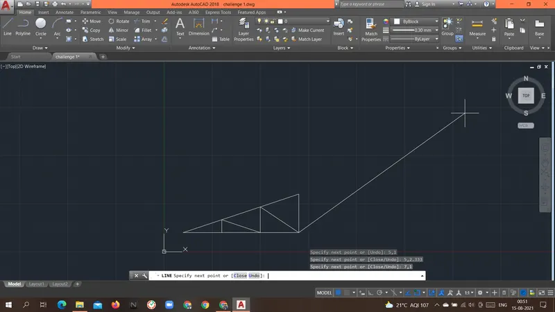
Specify next point or [Close/Undo]: c
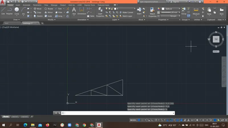
Result: Above geometry MONO PITCH was drawn with an Absolute coordinate system.
----------------------------------------------------------------------------------------------------------------------------------------------------------------------------
Aim: To create the geometries of the QUEEN POT TRUSS form above using Relative Polar coordinates system.
Introduction: there are different types of coordinate systems that can be used.
-
- Relative polar coordinates system.
- In this coordinate system, the relative distance and angle are given with the previous point.
- angle is given with respect to the positive x-axis(by default).
- Relative polar coordinates system.
Procedure:
QUEEN POST TRUSS
Command: L
LINE
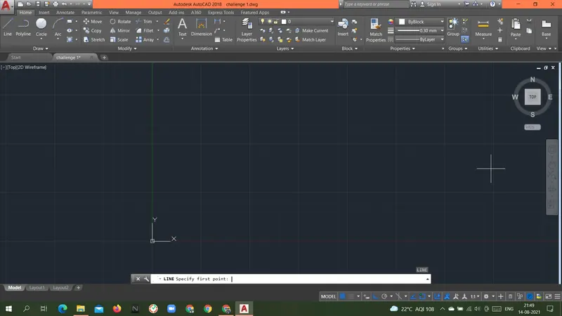
Specify first point: 1,1
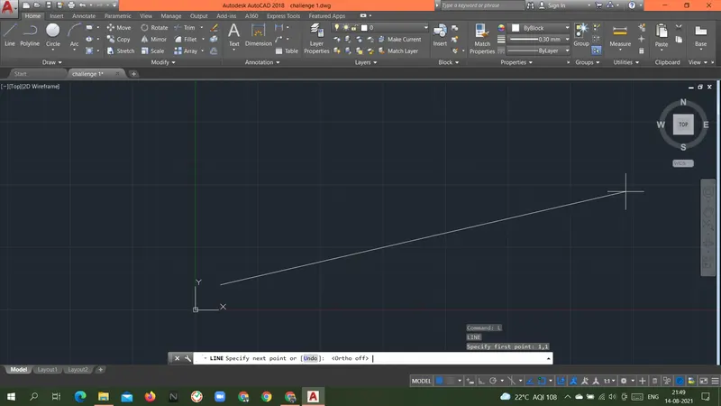
Specify next point or [Undo]: @4<90
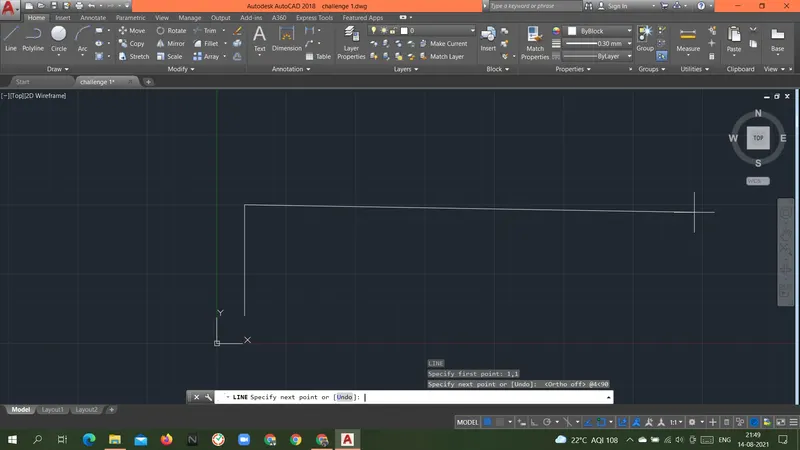
Specify next point or [Undo]: @5<45
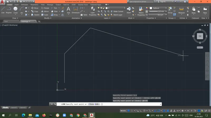
Specify next point or [Close/Undo]: @5<315
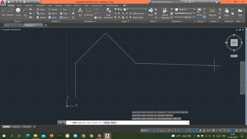
Specify next point or [Close/Undo]: @4<270
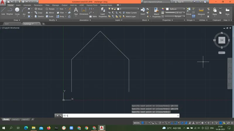
Specify next point or [Close/Undo]: enter
Command:
LINE
Specify first point: 1,5
Specify next point or [Undo]: @1<0
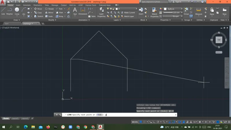
Specify next point or [Undo]: @1<90
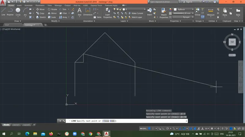
Specify next point or [Close/Undo]: @2.7256<338
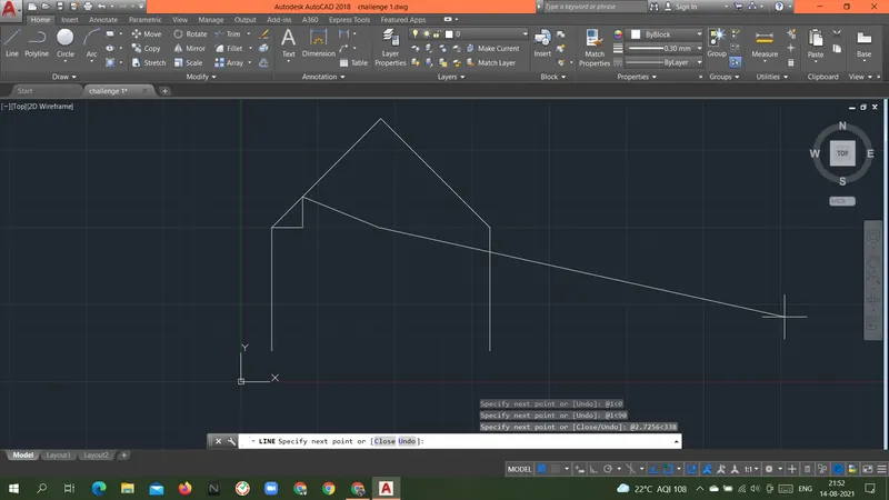
Specify next point or [Close/Undo]: @2.7256<22
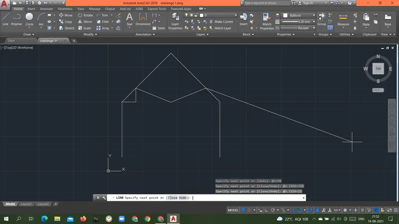
Specify next point or [Close/Undo]: @1<270
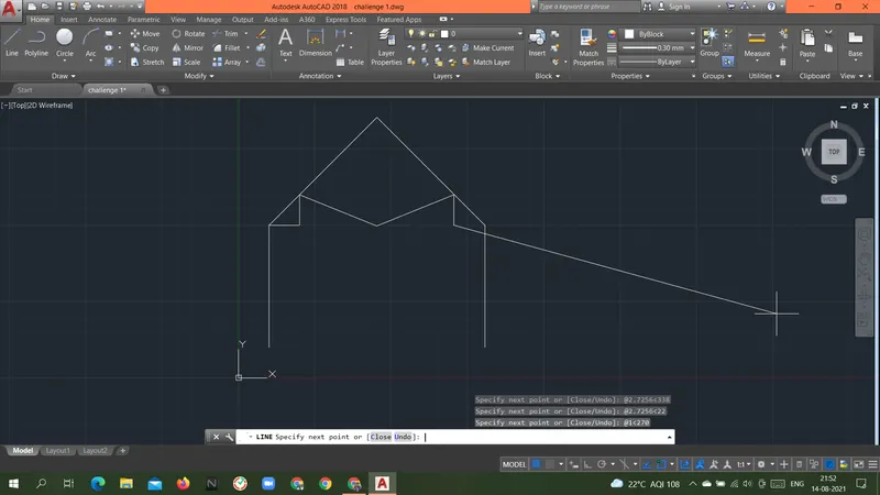
Specify next point or [Close/Undo]: @1<0
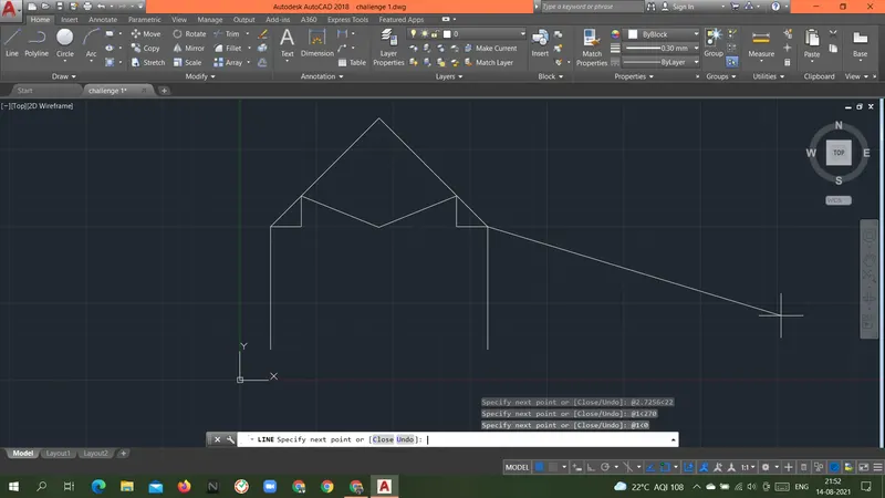
Specify next point or [Close/Undo]: @7.0711<180
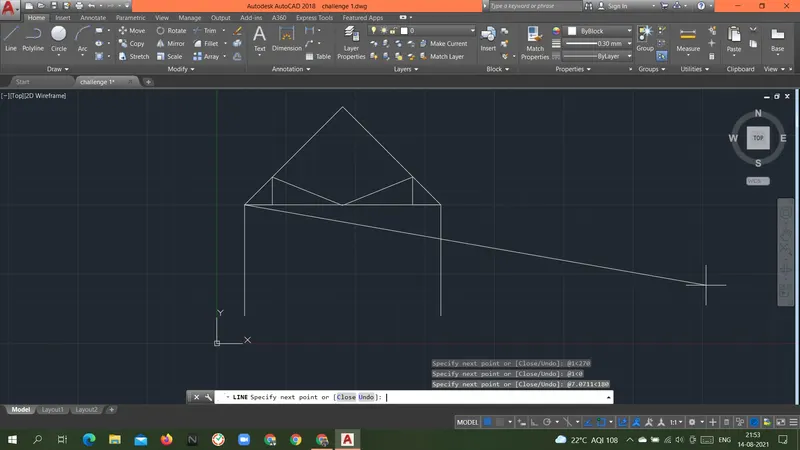
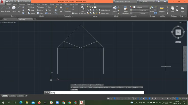
Specify next point or [Close/Undo]: c
Command: L
LINE
Specify first point: 4.5355,8.5355
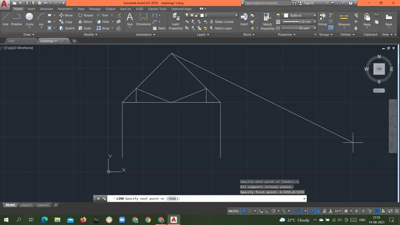
Specify next point or [Undo]: @3.5355<270
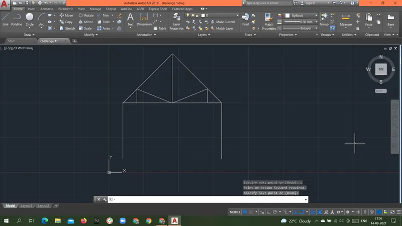
Specify next point or [Undo]: enter
Result: Above geometry QUEEN POST TRUSS was drawn with a Relative Polar coordinate system.