Drafting of various geometries using Chamfer, Fillet tool in AutoCad
AIM:
To Create a Diagram in the decimal unit using AUTOCAD.
INTRODUCTION:
Following are the commands which are used to draw the objects in AUTOCAD:
- Rectangle(REC): It is used to create a rectangle with the desired dimension.
- Polygon(POL): It is used to create a polygon by giving the no. of sides and circumscribed about the circle or Inscribed in a circle.
- Lines(L): Used to create a line. each line is created independently.
- Polyline(PL): Used to create a set of lines and curves(if any) to create an object of the desired dimension.
Following are the commands which are used to modify the objects in AUTOCAD:
- Move(M): It is used to move objects.
- Copy(CO): it is used to create multiple copies of the object selected.
- Offset(O): It is used to create offset from a selected object by giving the offset distance.
- Rotate(RO): It is used to rotate objects.
- Scale(SC): it is used to make the selected objects bigger or smaller by changing the scale factor.
- Fillet(F): It is used to create curved edges at the junction of two lines. radius can be adjusted as per requirement.
- Chamfer(CH): It is used to create straight edges at the junction of two lines, chamfer distance is can be adjusted.
- Snap tool(DS): It is used to set the minimum distance to move in the x & y-direction.
- Trim(TR): It is used to trim the extended part of the object at a desired place.
- Erase(E): it is used to erase the object which is not required.
PROCEDURE:
Specify first point:
Specify next point or [Undo]: 3.00
Specify next point or [Undo]: *Cancel*
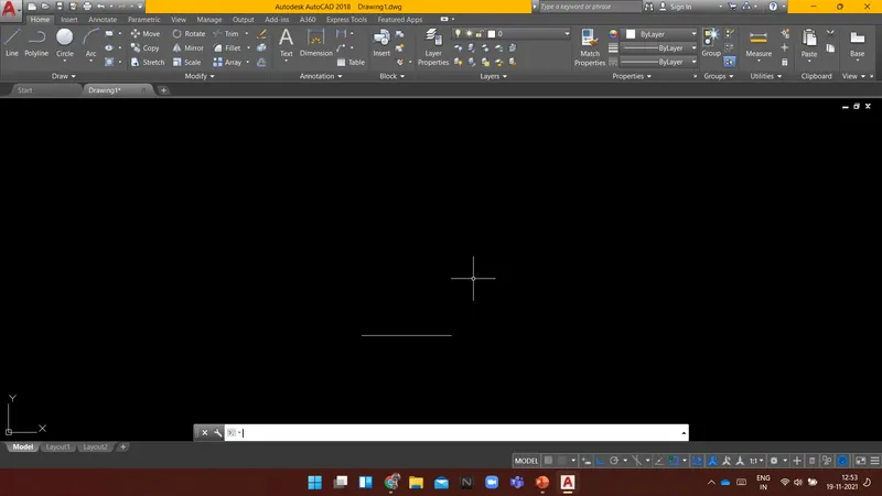
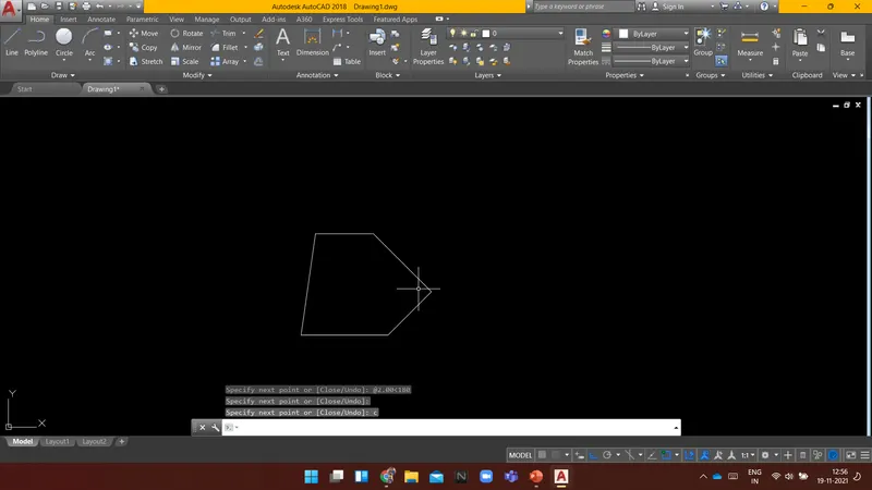
Command: L LINE
Specify first point:
Specify next point or [Undo]: @2.12<135
Specify next point or [Undo]: u
Specify next point or [Undo]: @2.12<45
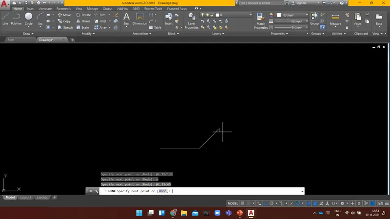
Specify next point or [Undo]: @2.83<@90
Point or option keyword required.
Specify next point or [Undo]: @2.83<90
Specify next point or [Close/Undo]: u
Specify next point or [Undo]: @2.83<135
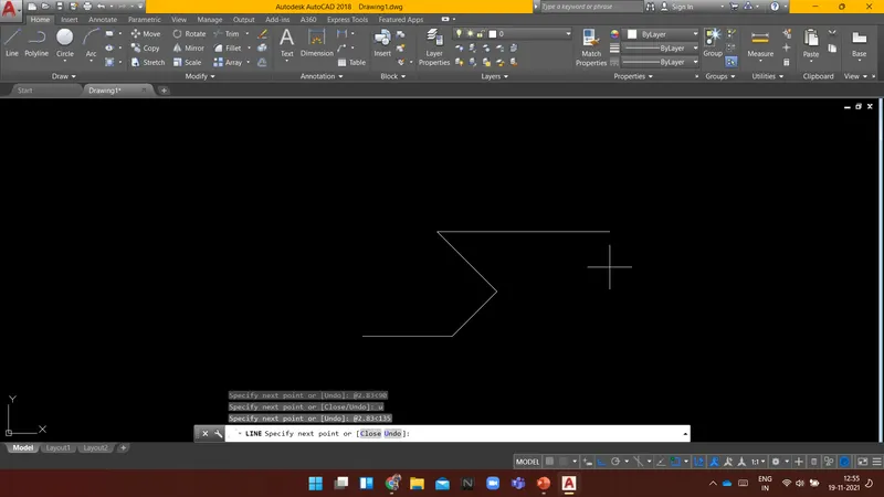
Specify next point or [Close/Undo]: @2.00<180
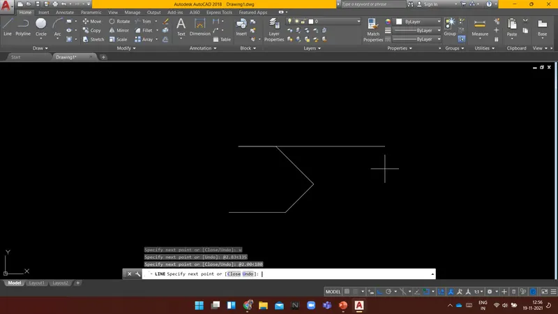
Specify next point or [Close/Undo]:
Specify next point or [Close/Undo]: c
Command: L LINE
Specify first point:
Specify next point or [Undo]: 1.50
Specify next point or [Undo]: 1
Specify next point or [Close/Undo]: 1.50
Specify next point or [Close/Undo]:
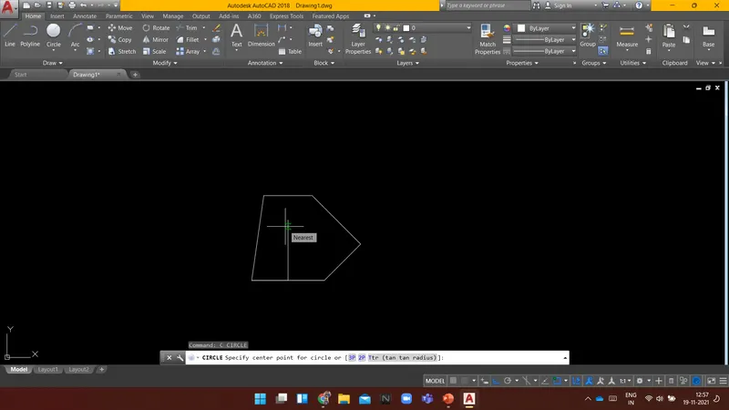
Command: C CIRCLE
Specify center point for circle or [3P/2P/Ttr (tan tan radius)]:
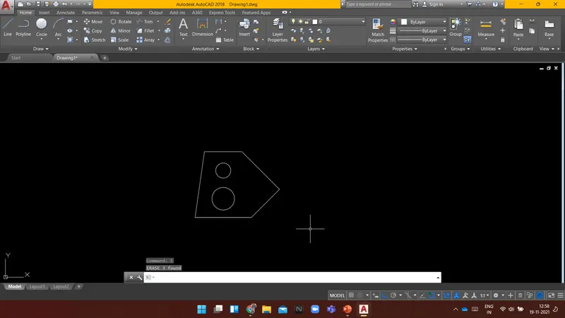
Specify radius of circle or [Diameter]: d Specify diameter of circle: 1.20
Command: C CIRCLE
Specify center point for circle or [3P/2P/Ttr (tan tan radius)]:
Specify radius of circle or [Diameter] <0.6000>: d Specify diameter of circle <1.2000>: 0.80
Command: CIRCLE
Specify center point for circle or [3P/2P/Ttr (tan tan radius)]: *Cancel*
Command:
Command:
Command:
Command: E
ERASE 3 found
Result: The given Diagram is drawn using AutoCAD.
----------------------------------------------------------------------------------------------------------------------------------------
AIM:
To Create a Diagram in an architectural unit using AUTOCAD.
INTRODUCTION:
Following are the commands which are used to draw the objects in AUTOCAD:
- Rectangle(REC): It is used to create a rectangle with the desired dimension.
- Polygon(POL): It is used to create a polygon by giving the no. of sides and circumscribed about the circle or Inscribed in a circle.
- Lines(L): Used to create a line. each line is created independently.
- Polyline(PL): Used to create a set of lines and curves(if any) to create an object of the desired dimension.
Following are the commands which are used to modify the objects in AUTOCAD:
- Move(M): It is used to move objects.
- Copy(CO): it is used to create multiple copies of the object selected.
- Offset(O): It is used to create offset from a selected object by giving the offset distance.
- Rotate(RO): It is used to rotate objects.
- Scale(SC): it is used to make the selected objects bigger or smaller by changing the scale factor.
- Fillet(F): It is used to create curved edges at the junction of two lines. radius can be adjusted as per requirement.
- Chamfer(CH): It is used to create straight edges at the junction of two lines, chamfer distance is can be adjusted.
- Snap tool(DS): It is used to set the minimum distance to move in the x & y-direction.
- Trim(TR): It is used to trim the extended part of the object at a desired place.
- Erase(E): it is used to erase the object which is not required.
PROCEDURE:
Command: PL PLINE
Specify start point:
Current line-width is 0'-0"
Specify next point or [Arc/Halfwidth/Length/Undo/Width]: 8'
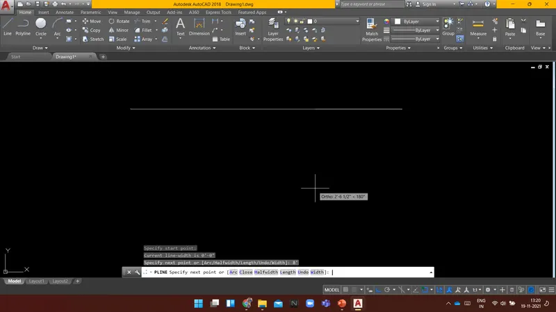
Specify next point or [Arc/Close/Halfwidth/Length/Undo/Width]: @1'9"<270
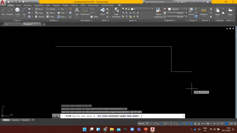
Specify next point or [Arc/Close/Halfwidth/Length/Undo/Width]: @2'10"<225
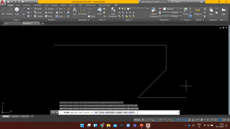
Specify next point or [Arc/Close/Halfwidth/Length/Undo/Width]:
Command: l LINE
Specify first point:
Specify next point or [Undo]: 2'5"
Specify next point or [Undo]:
>>Enter new value for ORTHOMODE <1>:
Resuming LINE command.
Specify next point or [Undo]: @3'<300
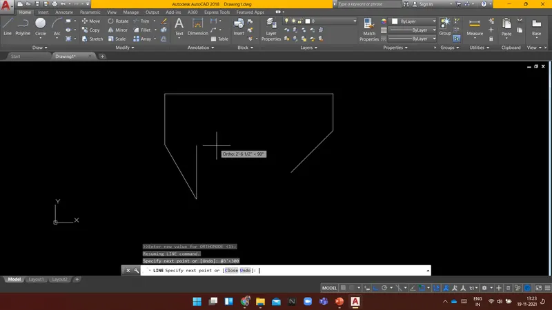
Specify next point or [Close/Undo]: @2'6"<30
Specify next point or [Close/Undo]:
Specify next point or [Close/Undo]: c
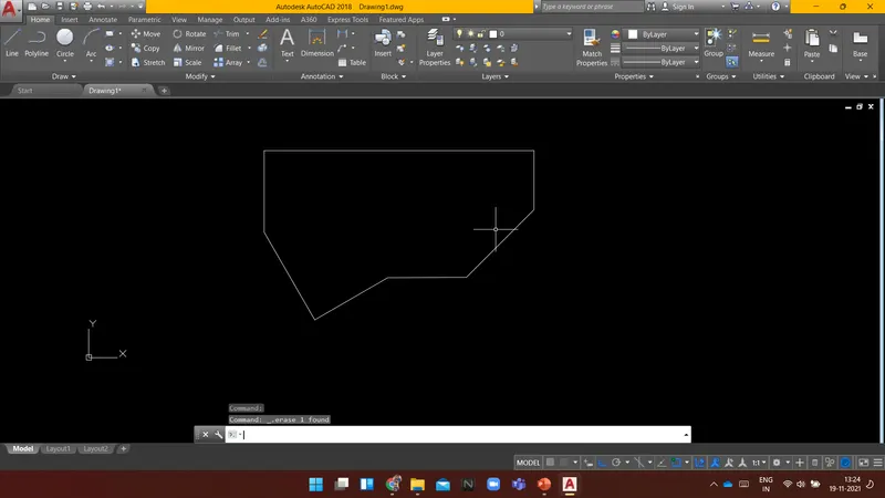
Result: The following was drawn in architectural units using AutoCAD.
----------------------------------------------------------------------------------------------------------------------------------------
AIM:
To Create a Diagram in an Engineering unit using AUTOCAD.
INTRODUCTION:
Following are the commands which are used to draw the objects in AUTOCAD:
- Rectangle(REC): It is used to create a rectangle with the desired dimension.
- Polygon(POL): It is used to create a polygon by giving the no. of sides and circumscribed about the circle or Inscribed in a circle.
- Lines(L): Used to create a line. each line is created independently.
- Polyline(PL): Used to create a set of lines and curves(if any) to create an object of the desired dimension.
Following are the commands which are used to modify the objects in AUTOCAD:
- Move(M): It is used to move objects.
- Copy(CO): it is used to create multiple copies of the object selected.
- Offset(O): It is used to create offset from a selected object by giving the offset distance.
- Rotate(RO): It is used to rotate objects.
- Scale(SC): it is used to make the selected objects bigger or smaller by changing the scale factor.
- Fillet(F): It is used to create curved edges at the junction of two lines. radius can be adjusted as per requirement.
- Chamfer(CH): It is used to create straight edges at the junction of two lines, chamfer distance is can be adjusted.
- Snap tool(DS): It is used to set the minimum distance to move in the x & y-direction.
- Trim(TR): It is used to trim the extended part of the object at a desired place.
- Erase(E): it is used to erase the object which is not required.
PROCEDURE:
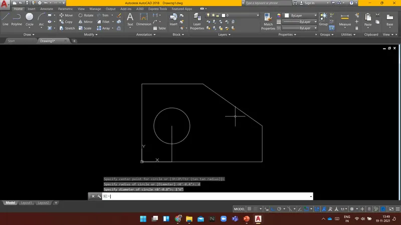
Command: L LINE
Specify first point: 0,0
Specify next point or [Undo]: 5'0.1"
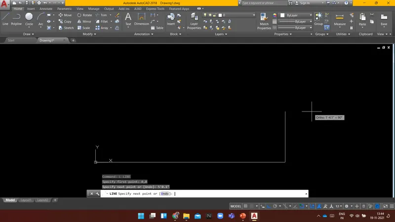
Specify next point or [Undo]: @1'6"<90
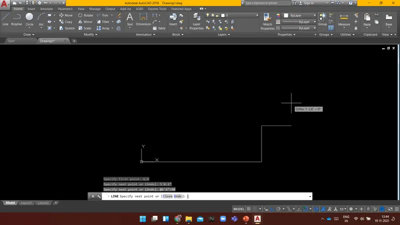
Specify next point or [Close/Undo]:
Command: L LINE
Specify first point:
Specify next point or [Undo]: *Cancel*
Command: L LINE
Specify first point:
Specify next point or [Undo]: 3'3"
Specify next point or [Undo]: @2'6.5"<0
Specify next point or [Close/Undo]:
Specify next point or [Close/Undo]:
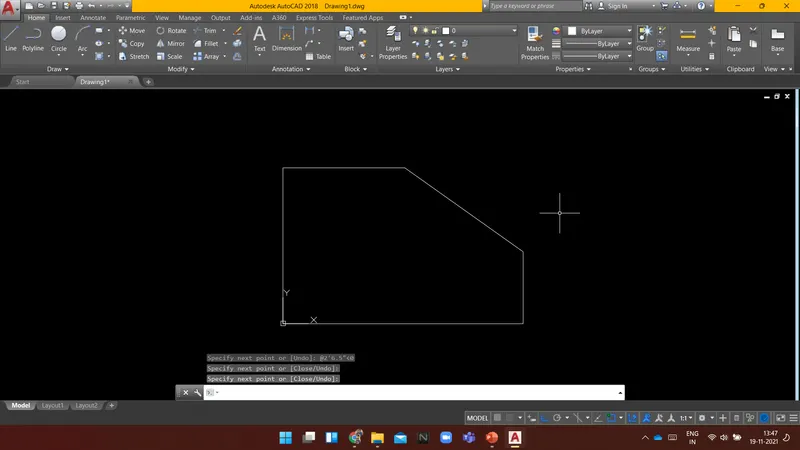
Command:
Command: L LINE
Specify first point:
Command: L LINE
Specify first point:
Specify next point or [Undo]: 1'3"
Specify next point or [Undo]: 1'6"
Specify next point or [Close/Undo]:
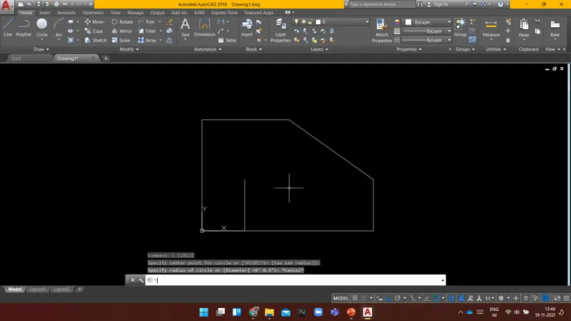
Command: C CIRCLE
Specify center point for circle or [3P/2P/Ttr (tan tan radius)]:
Specify radius of circle or [Diameter] <0'-0.4">: d
Specify diameter of circle <0'-0.8">: 1'6"
Command:
Command:
Command: E ERASE 2 found
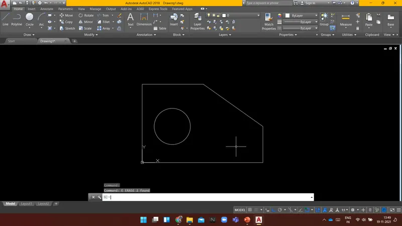
RESULT: The following was drawn in Engineering units using AutoCAD.
----------------------------------------------------------------------------------------------------------------------------------------
AIM:
To Create a Diagram using AUTOCAD.
INTRODUCTION:
Following are the commands which are used to draw the objects in AUTOCAD:
- Rectangle(REC): It is used to create a rectangle with the desired dimension.
- Polygon(POL): It is used to create a polygon by giving the no. of sides and circumscribed about the circle or Inscribed in a circle.
- Lines(L): Used to create a line. each line is created independently.
- Polyline(PL): Used to create a set of lines and curves(if any) to create an object of the desired dimension.
Following are the commands which are used to modify the objects in AUTOCAD:
- Move(M): It is used to move objects.
- Copy(CO): it is used to create multiple copies of the object selected.
- Offset(O): It is used to create offset from a selected object by giving the offset distance.
- Rotate(RO): It is used to rotate objects.
- Scale(SC): it is used to make the selected objects bigger or smaller by changing the scale factor.
- Fillet(F): It is used to create curved edges at the junction of two lines. radius can be adjusted as per requirement.
- Chamfer(CH): It is used to create straight edges at the junction of two lines, chamfer distance is can be adjusted.
- Snap tool(DS): It is used to set the minimum distance to move in the x & y-direction.
- Trim(TR): It is used to trim the extended part of the object at a desired place.
- Erase(E): it is used to erase the object which is not required.
PROCEDURE:
Command: L LINE
Specify first point:
Specify next point or [Undo]: 2
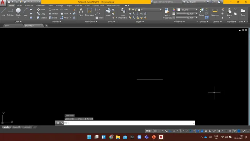
Specify next point or [Undo]: 2.5
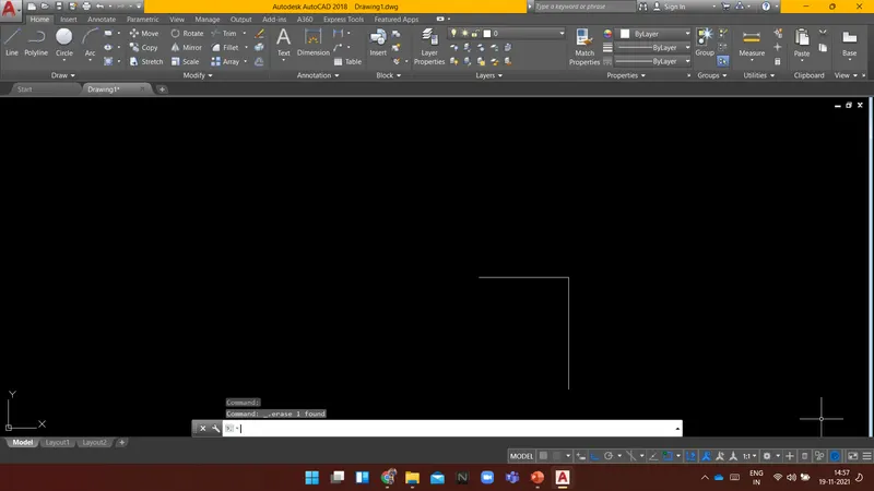
Specify next point or [Close/Undo]: 2.5
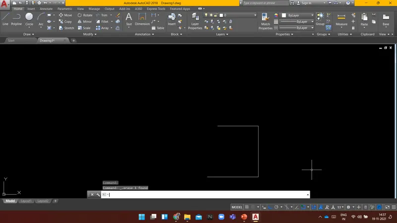
Specify next point or [Close/Undo]: 0.5
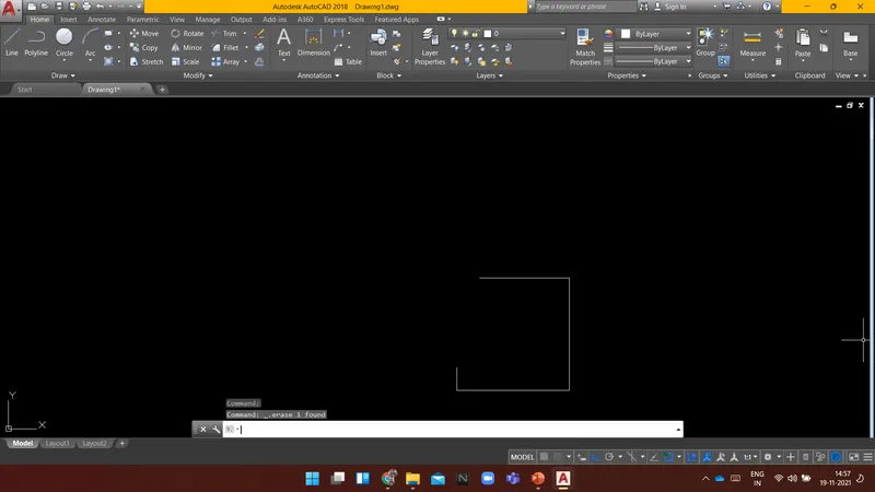
Specify next point or [Close/Undo]: 3
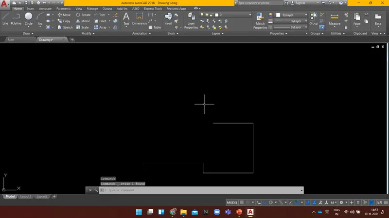
Specify next point or [Close/Undo]: 3.5
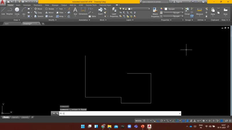
Specify next point or [Close/Undo]: 1
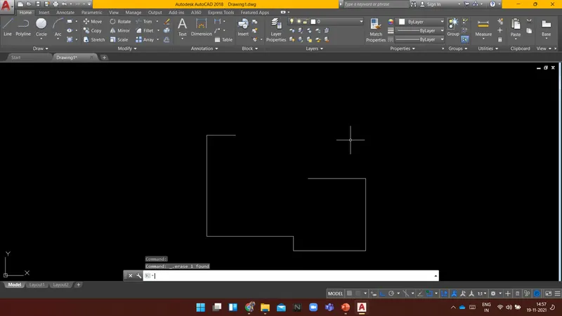
Specify next point or [Close/Undo]: 2
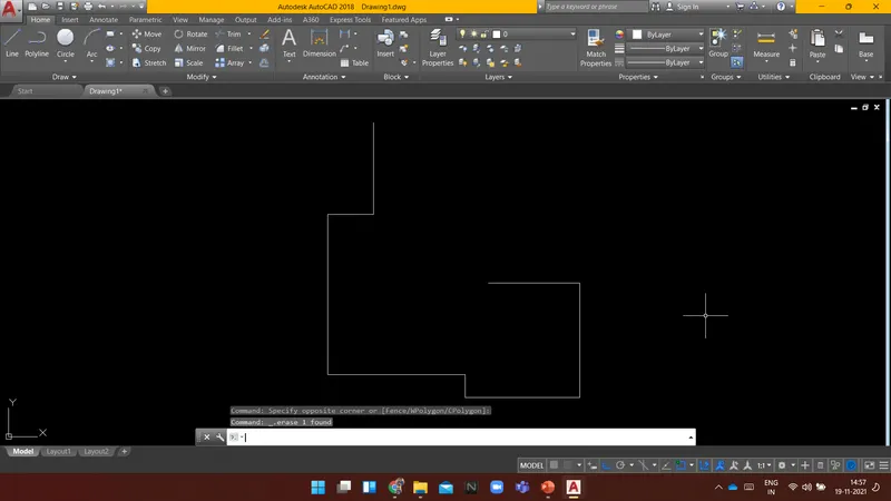
Specify next point or [Close/Undo]: 2.5
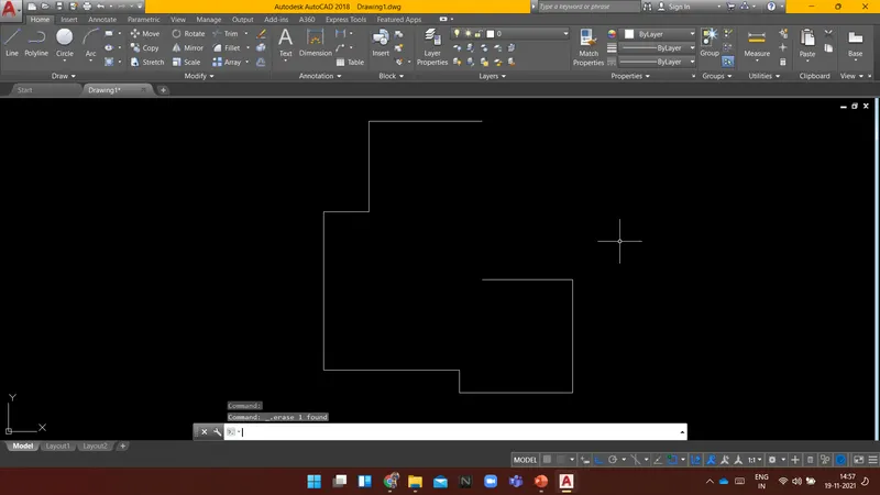
Specify next point or [Close/Undo]:
Specify next point or [Close/Undo]:
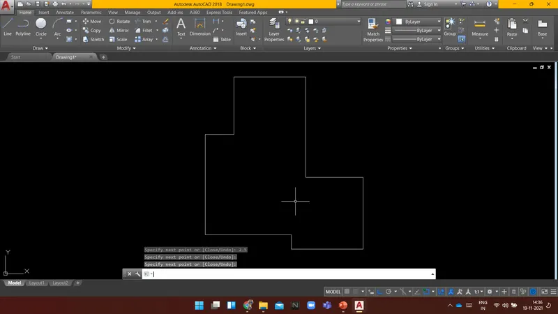
RESULT: The following diagram was drawn using AutoCAD.
----------------------------------------------------------------------------------------------------------------------------------------
AIM:
To Create a given diagram using AUTOCAD.
INTRODUCTION:
Following are the commands which are used to draw the objects in AUTOCAD:
- Rectangle(REC): It is used to create a rectangle with the desired dimension.
- Polygon(POL): It is used to create a polygon by giving the no. of sides and circumscribed about the circle or Inscribed in a circle.
- Lines(L): Used to create a line. each line is created independently.
- Polyline(PL): Used to create a set of lines and curves(if any) to create an object of the desired dimension.
Following are the commands which are used to modify the objects in AUTOCAD:
- Move(M): It is used to move objects.
- Copy(CO): it is used to create multiple copies of the object selected.
- Offset(O): It is used to create offset from a selected object by giving the offset distance.
- Rotate(RO): It is used to rotate objects.
- Scale(SC): it is used to make the selected objects bigger or smaller by changing the scale factor.
- Fillet(F): It is used to create curved edges at the junction of two lines. radius can be adjusted as per requirement.
- Chamfer(CH): It is used to create straight edges at the junction of two lines, chamfer distance is can be adjusted.
- Snap tool(DS): It is used to set the minimum distance to move in the x & y-direction.
- Trim(TR): It is used to trim the extended part of the object at a desired place.
- Erase(E): it is used to erase the object which is not required.
PROCEDURE:
Command:
Command: _rectang
Specify first corner point or [Chamfer/Elevation/Fillet/Thickness/Width]:
Specify other corner point or [Area/Dimensions/Rotation]: d
Specify length for rectangles <10.0>: 11.50
Specify width for rectangles <10.0>: 6
Specify other corner point or [Area/Dimensions/Rotation]:
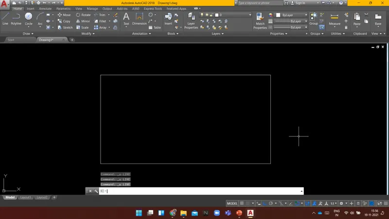
Command: L LINE
Specify first point:
Specify next point or [Undo]:
Specify next point or [Undo]:
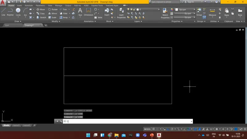
Command:
Command: L LINE
Specify first point:
Specify next point or [Undo]: 2.75
Specify next point or [Undo]:
Specify next point or [Close/Undo]:
Command: L LINE
Specify first point:
Specify next point or [Undo]: 1.5
Specify next point or [Undo]:
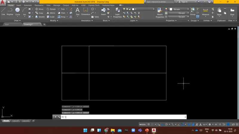
Command:
Command:
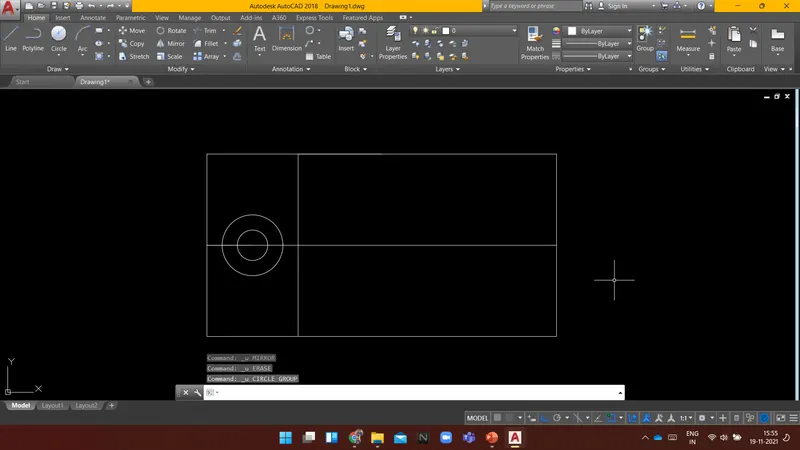
Command: _circle
Specify center point for circle or [3P/2P/Ttr (tan tan radius)]:
Specify radius of circle or [Diameter] <250.0>: _d Specify diameter of circle <500.0>: 1
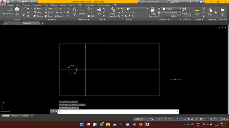
Command: CIRCLE
Specify center point for circle or [3P/2P/Ttr (tan tan radius)]:
Specify radius of circle or [Diameter] <0.5>: d Specify diameter of circle <1.0>: 2
Command:
Command:
Command: _circle
Specify center point for circle or [3P/2P/Ttr (tan tan radius)]:
Specify radius of circle or [Diameter] <1.0>: _d Specify diameter of circle <2.0>: 3
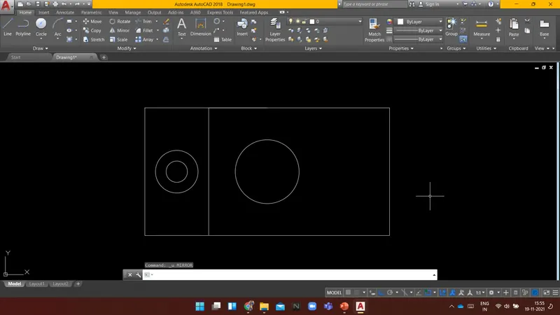
Command: E ERASE
Select objects: 1 found
Select objects: 1 found, 2 total
Select objects:
Command: MI MIRROR
Select objects: 1 found
Select objects: 1 found, 2 total
Select objects: Specify opposite corner: 0 found
Select objects: 1 found, 3 total
Select objects: Specify first point of mirror line:
Specify second point of mirror line:
Erase source objects? [Yes/No] : n
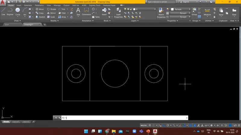
RESULT: The following diagram is drawn using AutoCAD.
----------------------------------------------------------------------------------------------------------------------------------------
AIM:
To Create a given diagram using AUTOCAD.
INTRODUCTION:
Following are the commands which are used to draw the objects in AUTOCAD:
- Rectangle(REC): It is used to create a rectangle with the desired dimension.
- Polygon(POL): It is used to create a polygon by giving the no. of sides and circumscribed about the circle or Inscribed in a circle.
- Lines(L): Used to create a line. each line is created independently.
- Polyline(PL): Used to create a set of lines and curves(if any) to create an object of the desired dimension.
Following are the commands which are used to modify the objects in AUTOCAD:
- Move(M): It is used to move objects.
- Copy(CO): it is used to create multiple copies of the object selected.
- Offset(O): It is used to create offset from a selected object by giving the offset distance.
- Rotate(RO): It is used to rotate objects.
- Scale(SC): it is used to make the selected objects bigger or smaller by changing the scale factor.
- Fillet(F): It is used to create curved edges at the junction of two lines. radius can be adjusted as per requirement.
- Chamfer(CH): It is used to create straight edges at the junction of two lines, chamfer distance is can be adjusted.
- Snap tool(DS): It is used to set the minimum distance to move in the x & y-direction.
- Trim(TR): It is used to trim the extended part of the object at a desired place.
- Erase(E): it is used to erase the object which is not required.
PROCEDURE:
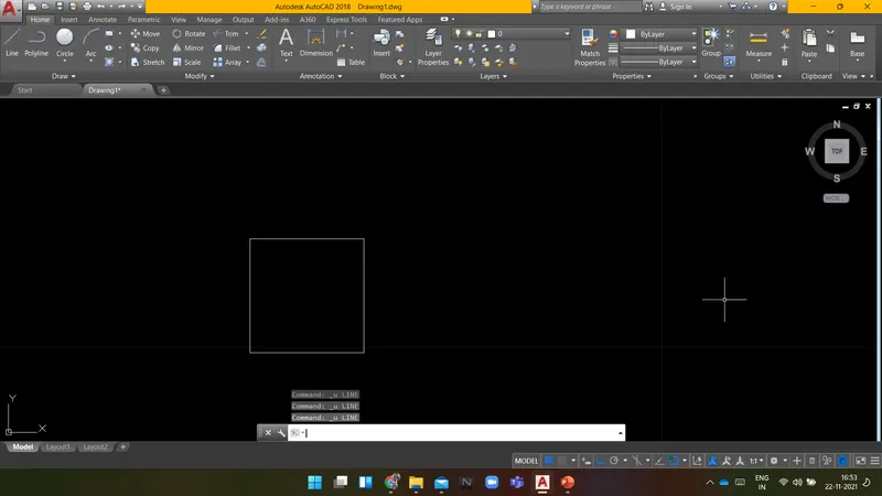
Command: L LINE
Specify first point:
Specify next point or [Undo]: 1
Specify next point or [Undo]: 0.5
Specify next point or [Close/Undo]: 1.5
Specify next point or [Close/Undo]: 0.5
Specify next point or [Close/Undo]: 1.5
Specify next point or [Close/Undo]: u
Specify next point or [Close/Undo]: 1
Specify next point or [Close/Undo]: .5
Specify next point or [Close/Undo]: .5
Specify next point or [Close/Undo]: .5
Specify next point or [Close/Undo]:
Command: L LINE
Specify first point:
Specify next point or [Undo]:
Specify next point or [Undo]:
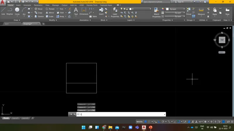
Command: LINE
Specify first point:
Specify next point or [Undo]:
Specify next point or [Undo]:
Command: LINE
Specify first point:
Specify next point or [Undo]:
Specify next point or [Undo]:
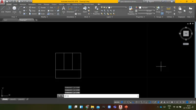
Command: LINE
Specify first point:
Specify next point or [Undo]: 2
Specify next point or [Undo]: 1.5
Specify next point or [Close/Undo]: 0.5
Specify next point or [Close/Undo]: 1
Specify next point or [Close/Undo]: 1.5
Specify next point or [Close/Undo]:
Specify next point or [Close/Undo]:
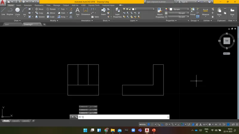
Command: LINE
Specify first point:
Specify next point or [Undo]:
Specify next point or [Undo]:
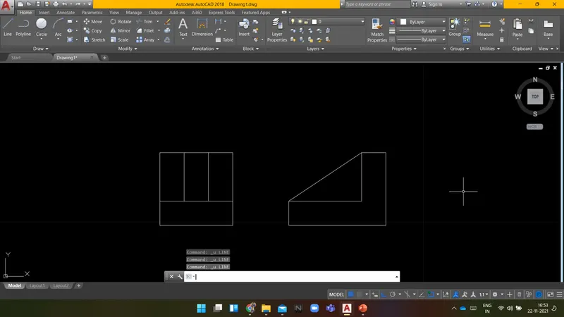
Command: LINE
Specify first point:
Specify next point or [Undo]: 2
Specify next point or [Undo]: .5
Specify next point or [Close/Undo]: .5
Specify next point or [Close/Undo]: u
Specify next point or [Close/Undo]: .5
Specify next point or [Close/Undo]: .5
Specify next point or [Close/Undo]: 2
Specify next point or [Close/Undo]: 1.5
Specify next point or [Close/Undo]:
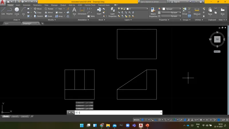
Command: LINE
Specify first point:
Specify next point or [Undo]:
Specify next point or [Undo]:
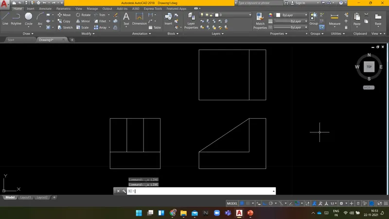
Command: L LINE
Specify first point:
Specify next point or [Undo]:
Specify next point or [Undo]:
Command: LINE
Specify first point:
Specify next point or [Undo]:
Specify next point or [Undo]:
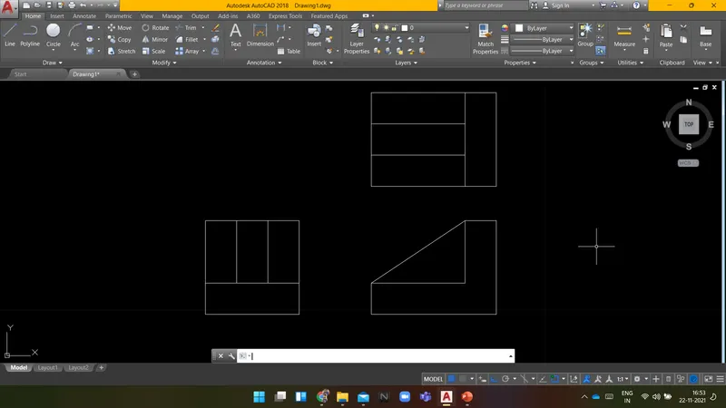
RESULT: The following diagram is drawn using AutoCAD.
----------------------------------------------------------------------------------------------------------------------------------------
AIM:
To Create a given diagram using AUTOCAD.
INTRODUCTION:
Following are the commands which are used to draw the objects in AUTOCAD:
- Rectangle(REC): It is used to create a rectangle with the desired dimension.
- Polygon(POL): It is used to create a polygon by giving the no. of sides and circumscribed about the circle or Inscribed in a circle.
- Lines(L): Used to create a line. each line is created independently.
- Polyline(PL): Used to create a set of lines and curves(if any) to create an object of the desired dimension.
Following are the commands which are used to modify the objects in AUTOCAD:
- Move(M): It is used to move objects.
- Copy(CO): it is used to create multiple copies of the object selected.
- Offset(O): It is used to create offset from a selected object by giving the offset distance.
- Rotate(RO): It is used to rotate objects.
- Scale(SC): it is used to make the selected objects bigger or smaller by changing the scale factor.
- Fillet(F): It is used to create curved edges at the junction of two lines. radius can be adjusted as per requirement.
- Chamfer(CH): It is used to create straight edges at the junction of two lines, chamfer distance is can be adjusted.
- Snap tool(DS): It is used to set the minimum distance to move in the x & y-direction.
- Trim(TR): It is used to trim the extended part of the object at a desired place.
- Erase(E): it is used to erase the object which is not required.
PROCEDURE:
Specify first point:
Specify next point or [Undo]: 100
Specify next point or [Undo]: 210
Specify next point or [Close/Undo]: 75
Specify next point or [Close/Undo]: 25
Specify next point or [Close/Undo]: 25
Specify next point or [Close/Undo]:
Specify next point or [Close/Undo]:
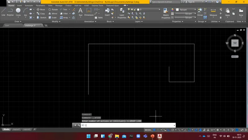
Command: LINE
Specify first point:
Specify next point or [Undo]: 25
Specify next point or [Undo]: 25
Specify next point or [Close/Undo]:
Specify next point or [Close/Undo]:
Command:
Command:
Command: _circle
Specify center point for circle or [3P/2P/Ttr (tan tan radius)]:
Specify radius of circle or [Diameter]:
Command: CIRCLE
Specify center point for circle or [3P/2P/Ttr (tan tan radius)]:
Specify radius of circle or [Diameter] <25.0000>:
Command: O OFFSET
Current settings: Erase source=No Layer=Source OFFSETGAPTYPE=0
Specify offset distance or [Through/Erase/Layer] : 60
Select object to offset or [Exit/Undo] :
Specify point on side to offset or [Exit/Multiple/Undo] :
Select object to offset or [Exit/Undo] :
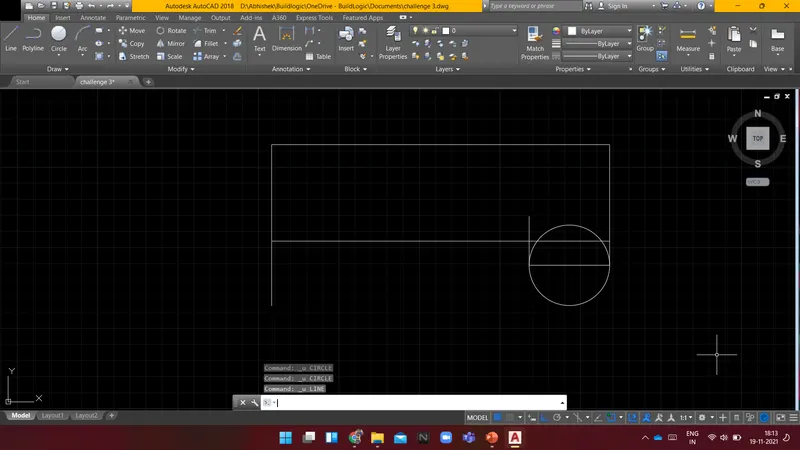
Command: C CIRCLE
Specify center point for circle or [3P/2P/Ttr (tan tan radius)]:
Specify radius of circle or [Diameter] <25.0000>: d Specify diameter of circle <50.0000>: 50
Command: C
CIRCLE
Specify center point for circle or [3P/2P/Ttr (tan tan radius)]:
Specify radius of circle or [Diameter] <25.0000>: d Specify diameter of circle <50.0000>: 50
Command:
Command: _.erase 1 found
Command:
Command: _.erase 1 found
Command:
Command: _.erase 1 found
Command:
Command: _.erase 1 found
Command:
Command: _.erase 1 found
Command:
Command: _.erase 1 found
Command: l LINE
Specify first point:
Specify next point or [Undo]: 35
Specify next point or [Undo]: 35
Specify next point or [Close/Undo]:
Specify next point or [Close/Undo]:
Command: C CIRCLE
Specify center point for circle or [3P/2P/Ttr (tan tan radius)]:
Specify radius of circle or [Diameter] <25.0000>: *Cancel*
Command: C CIRCLE
Specify center point for circle or [3P/2P/Ttr (tan tan radius)]:
Specify radius of circle or [Diameter] <25.0000>:
Command: C CIRCLE
Specify center point for circle or [3P/2P/Ttr (tan tan radius)]:
Specify radius of circle or [Diameter] <35.0000>:
Command: CIRCLE
Specify center point for circle or [3P/2P/Ttr (tan tan radius)]:
Specify radius of circle or [Diameter] <35.0000>: d Specify diameter of circle <70.0000>: 50
Command: C CIRCLE
Specify center point for circle or [3P/2P/Ttr (tan tan radius)]:
Specify radius of circle or [Diameter] <25.0000>: d Specify diameter of circle <50.0000>: 30
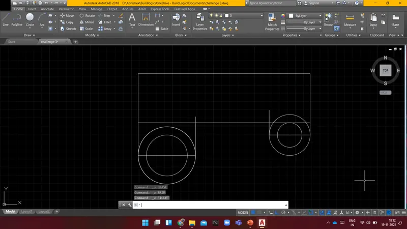
Command: F FILLET
Current settings: Mode = TRIM, Radius = 0.0000
Select first object or [Undo/Polyline/Radius/Trim/Multiple]: r Specify fillet radius <0.0000>: 6
Select first object or [Undo/Polyline/Radius/Trim/Multiple]:
Select second object or shift-select to apply corner or [Radius]:
Command: TR TRIM
Current settings: Projection=UCS, Edge=None
Select cutting edges ...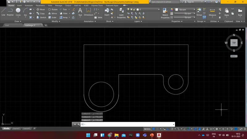
Command: f FILLET
Current settings: Mode = TRIM, Radius = 6.0000
Select first object or [Undo/Polyline/Radius/Trim/Multiple]: r Specify fillet radius <6.0000>: 20
Select first object or [Undo/Polyline/Radius/Trim/Multiple]:
Select second object or shift-select to apply corner or [Radius]:
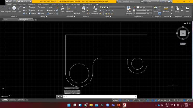
Command: FILLET
Current settings: Mode = TRIM, Radius = 20.0000
Select first object or [Undo/Polyline/Radius/Trim/Multiple]: r Specify fillet radius <20.0000>: 15
Select first object or [Undo/Polyline/Radius/Trim/Multiple]:
Select second object or shift-select to apply corner or [Radius]:
Command: FILLET
Current settings: Mode = TRIM, Radius = 15.0000
Select first object or [Undo/Polyline/Radius/Trim/Multiple]:
Select second object or shift-select to apply corner or [Radius]:
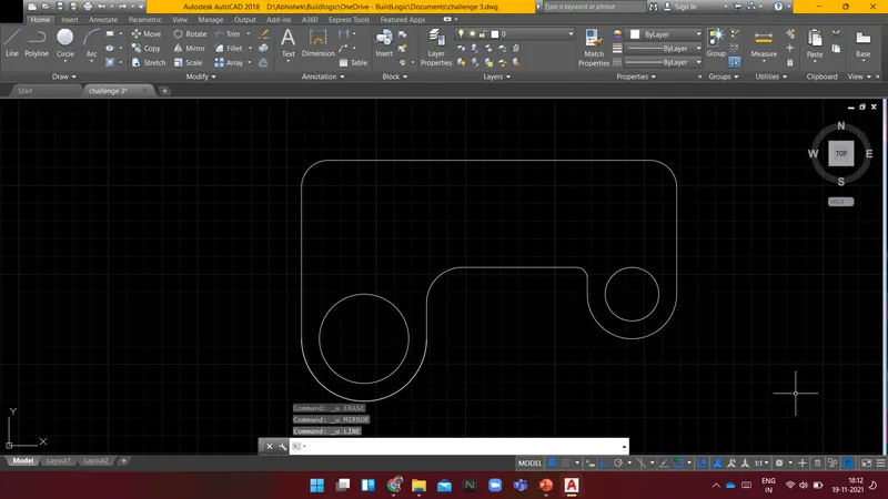
Command: L LINE
Specify first point:
Specify next point or [Undo]: 10
Specify next point or [Undo]: 15
Specify next point or [Close/Undo]: 30
Specify next point or [Close/Undo]: 70
Specify next point or [Close/Undo]: 30
Specify next point or [Close/Undo]:
Specify next point or [Close/Undo]:
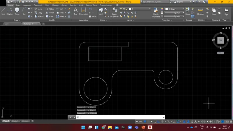
Command: MI MIRROR
Select objects: Specify opposite corner: 6 found
Select objects: Specify first point of mirror line:
Specify second point of mirror line:
Erase source objects? [Yes/No] : n
Command: E ERASE
Select objects: 1 found
Select objects: 1 found, 2 total
Select objects: 1 found, 3 total
Select objects: 1 found (1 duplicate), 3 total
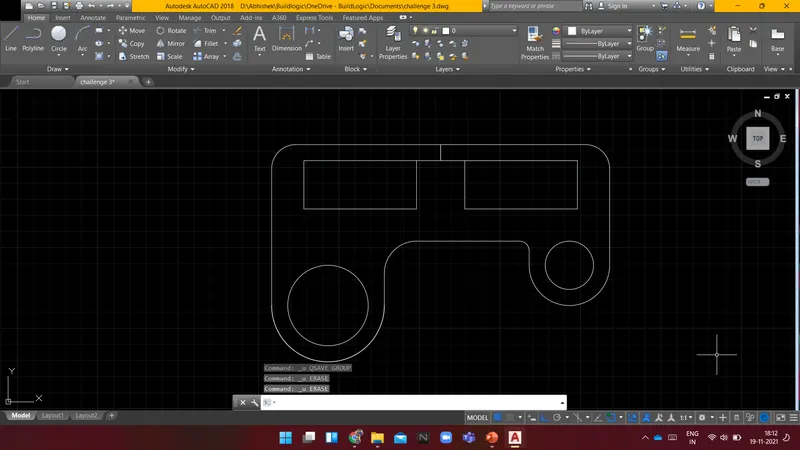
Select objects:
Command:
Command: E
ERASE 1 found
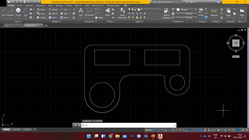
RESULT: The following diagram is drawn using AutoCAD.
----------------------------------------------------------------------------------------------------------------------------------------
AIM:
To Create a given diagram using AUTOCAD.
INTRODUCTION:
Following are the commands which are used to draw the objects in AUTOCAD:
- Rectangle(REC): It is used to create a rectangle with the desired dimension.
- Polygon(POL): It is used to create a polygon by giving the no. of sides and circumscribed about the circle or Inscribed in a circle.
- Lines(L): Used to create a line. each line is created independently.
- Polyline(PL): Used to create a set of lines and curves(if any) to create an object of the desired dimension.
Following are the commands which are used to modify the objects in AUTOCAD:
- Move(M): It is used to move objects.
- Copy(CO): it is used to create multiple copies of the object selected.
- Offset(O): It is used to create offset from a selected object by giving the offset distance.
- Rotate(RO): It is used to rotate objects.
- Scale(SC): it is used to make the selected objects bigger or smaller by changing the scale factor.
- Fillet(F): It is used to create curved edges at the junction of two lines. radius can be adjusted as per requirement.
- Chamfer(CH): It is used to create straight edges at the junction of two lines, chamfer distance is can be adjusted.
- Snap tool(DS): It is used to set the minimum distance to move in the x & y-direction.
- Trim(TR): It is used to trim the extended part of the object at a desired place.
- Erase(E): it is used to erase the object which is not required.
PROCEDURE:
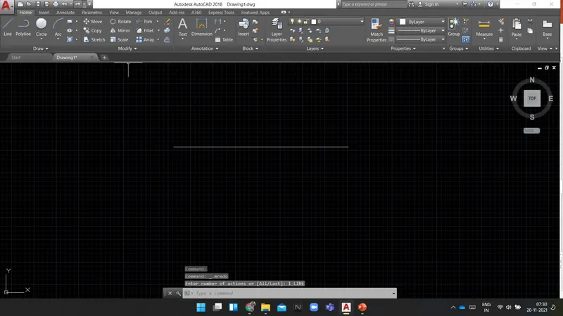
Command: L LINE
Specify first point:
Specify next point or [Undo]: 32'6"
Specify next point or [Undo]:
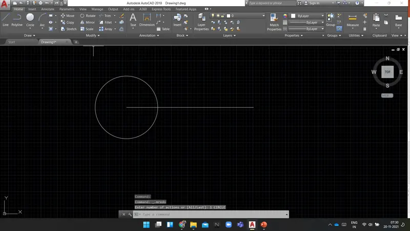
Command: C
CIRCLE
Specify center point for circle or [3P/2P/Ttr (tan tan radius)]:
Specify radius of circle or [Diameter]: 8'
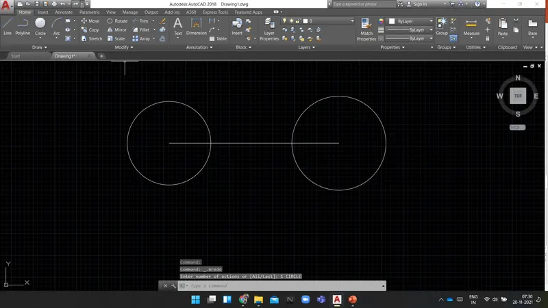
Command: CIRCLE
Specify center point for circle or [3P/2P/Ttr (tan tan radius)]:
Specify radius of circle or [Diameter] <8'-0.0000">: 9'
Command: C CIRCLE
Specify center point for circle or [3P/2P/Ttr (tan tan radius)]: t
Specify point on object for first tangent of circle:
Specify point on object for second tangent of circle:
Specify radius of circle <9'-0.0000">: 41'8"
Command: UNDO
Current settings: Auto = On, Control = All, Combine = Yes, Layer = Yes
Enter the number of operations to undo or [Auto/Control/BEgin/End/Mark/Back] <1>: 1
CIRCLE
Command: C CIRCLE
Specify center point for circle or [3P/2P/Ttr (tan tan radius)]: t
Specify point on object for first tangent of circle:
Specify point on object for second tangent of circle:
Specify radius of circle <9'-0.0000">: 41'8"
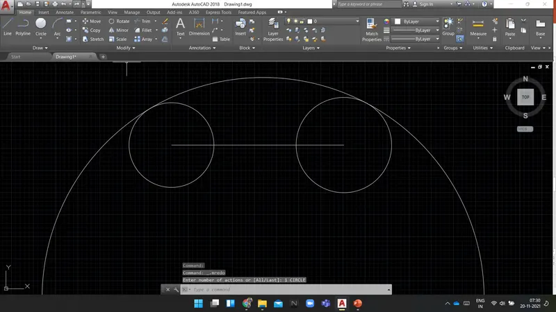
Command: C CIRCLE
Specify center point for circle or [3P/2P/Ttr (tan tan radius)]: t
Specify point on object for first tangent of circle:
Specify point on object for second tangent of circle:
Specify radius of circle <41'-8.0000">: 20'10"
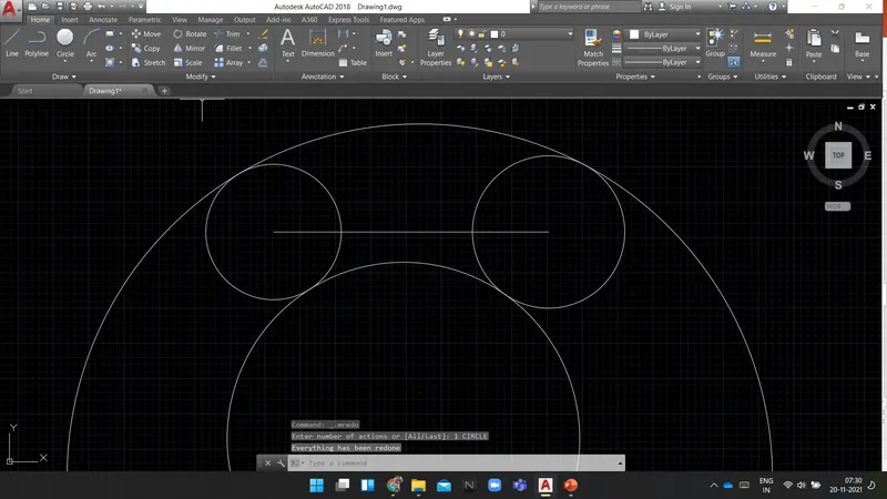
Command: E ERASE
Select objects: 1 found
Select objects:
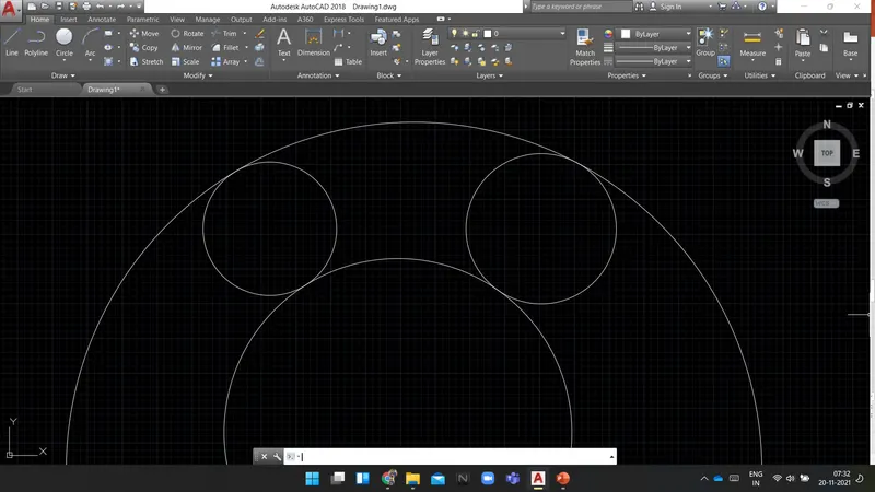
Command: TR TRIM
Current settings: Projection=UCS, Edge=None
Select cutting edges ...
Select objects
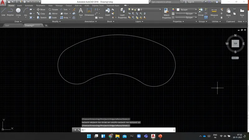
RESULT: The following diagram is drawn using AutoCAD.
----------------------------------------------------------------------------------------------------------------------------------------
AIM:
To Create a given diagram using AUTOCAD.
INTRODUCTION:
Following are the commands which are used to draw the objects in AUTOCAD:
- Rectangle(REC): It is used to create a rectangle with the desired dimension.
- Polygon(POL): It is used to create a polygon by giving the no. of sides and circumscribed about the circle or Inscribed in a circle.
- Lines(L): Used to create a line. each line is created independently.
- Polyline(PL): Used to create a set of lines and curves(if any) to create an object of the desired dimension.
Following are the commands which are used to modify the objects in AUTOCAD:
- Move(M): It is used to move objects.
- Copy(CO): it is used to create multiple copies of the object selected.
- Offset(O): It is used to create offset from a selected object by giving the offset distance.
- Rotate(RO): It is used to rotate objects.
- Scale(SC): it is used to make the selected objects bigger or smaller by changing the scale factor.
- Fillet(F): It is used to create curved edges at the junction of two lines. radius can be adjusted as per requirement.
- Chamfer(CH): It is used to create straight edges at the junction of two lines, chamfer distance is can be adjusted.
- Snap tool(DS): It is used to set the minimum distance to move in the x & y-direction.
- Trim(TR): It is used to trim the extended part of the object at a desired place.
- Erase(E): it is used to erase the object which is not required.
PROCEDURE:
Command: _rectang
Specify first corner point or [Chamfer/Elevation/Fillet/Thickness/Width]:
Specify other corner point or [Area/Dimensions/Rotation]: d
Specify length for rectangles <0'-10.0000">: 20'
Specify width for rectangles <0'-10.0000">: 20'
Specify other corner point or [Area/Dimensions/Rotation]:
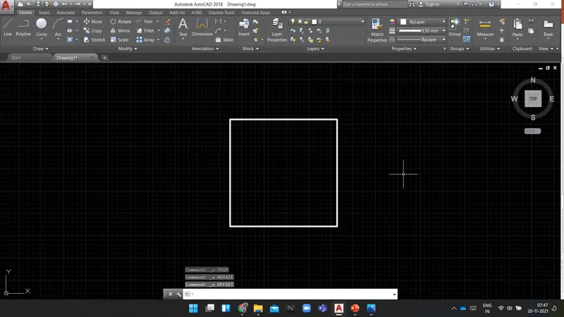
Command: O OFFSET
Current settings: Erase source=No Layer=Source OFFSETGAPTYPE=0
Specify offset distance or [Through/Erase/Layer] <3'-0.0000">: 2'
Select object to offset or [Exit/Undo] :
Specify point on side to offset or [Exit/Multiple/Undo] :
Select object to offset or [Exit/Undo] :
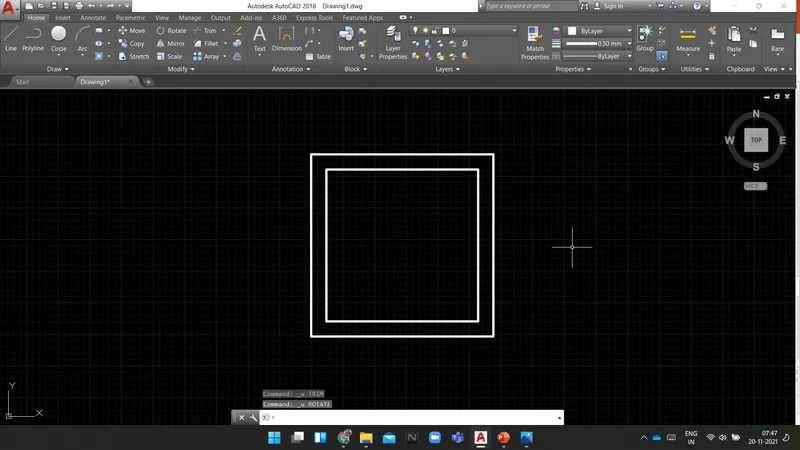
Command: RO ROTATE
Current positive angle in UCS: ANGDIR=counterclockwise ANGBASE=0
Select objects: 1 found
Select objects: 1 found, 2 total
Select objects:
Specify base point:
Specify rotation angle or [Copy/Reference] <0>: 45
Command:
Command:
Command: _.undo Current settings: Auto = On, Control = All, Combine = Yes, Layer = Yes
Enter the number of operations to undo or [Auto/Control/BEgin/End/Mark/Back] <1>: 1 ROTATE
Command: RO ROTATE
Current positive angle in UCS: ANGDIR=counterclockwise ANGBASE=0
Select objects: Specify opposite corner: 2 found
Select objects:
Specify base point:
Specify rotation angle or [Copy/Reference] <0>: c Rotating a copy of the selected objects.
Specify rotation angle or [Copy/Reference] <0>: 45
Command: Specify opposite corner or [Fence/WPolygon/CPolygon]:
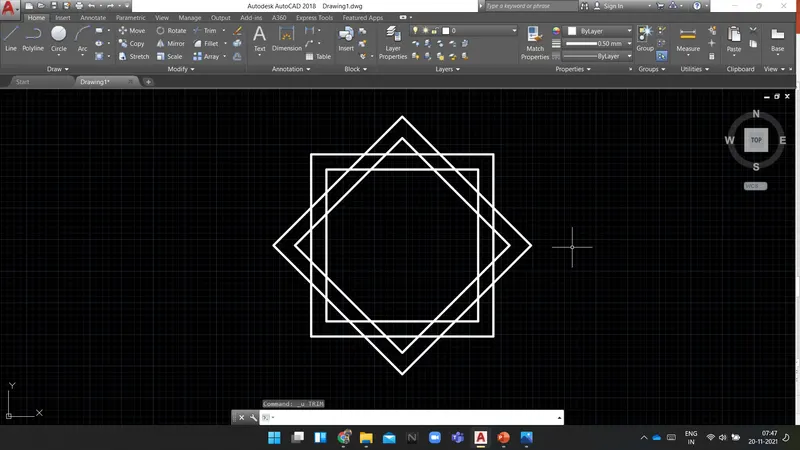
Command: TR TRIM
Current settings: Projection=UCS, Edge=None
Select cutting edges ... 4 found
Select object to trim or shift-select to extend or
[Fence/Crossing/Project/Edge/eRase/Undo]:
Select object to trim or shift-select to extend or
[Fence/Crossing/Project/Edge/eRase/Undo]:
Select object to trim or shift-select to extend or
[Fence/Crossing/Project/Edge/eRase/Undo]:
Select object to trim or shift-select to extend or
[Fence/Crossing/Project/Edge/eRase/Undo]:
Select object to trim or shift-select to extend or
[Fence/Crossing/Project/Edge/eRase/Undo]:
Select object to trim or shift-select to extend or
[Fence/Crossing/Project/Edge/eRase/Undo]:
Select object to trim or shift-select to extend or
[Fence/Crossing/Project/Edge/eRase/Undo]:
Select object to trim or shift-select to extend or
[Fence/Crossing/Project/Edge/eRase/Undo]:
Select object to trim or shift-select to extend or
[Fence/Crossing/Project/Edge/eRase/Undo]:
Select object to trim or shift-select to extend or
[Fence/Crossing/Project/Edge/eRase/Undo]:
Select object to trim or shift-select to extend or
[Fence/Crossing/Project/Edge/eRase/Undo]:
Select object to trim or shift-select to extend or
[Fence/Crossing/Project/Edge/eRase/Undo]:
Select object to trim or shift-select to extend or
[Fence/Crossing/Project/Edge/eRase/Undo]:
Select object to trim or shift-select to extend or
[Fence/Crossing/Project/Edge/eRase/Undo]:
Select object to trim or shift-select to extend or
[Fence/Crossing/Project/Edge/eRase/Undo]:
Select object to trim or shift-select to extend or
[Fence/Crossing/Project/Edge/eRase/Undo]:
Select object to trim or shift-select to extend or
[Fence/Crossing/Project/Edge/eRase/Undo]:
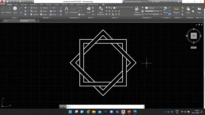
RESULT: The following diagram is drawn using AutoCAD.
----------------------------------------------------------------------------------------------------------------------------------------
AIM:
To Create a Cross-section of a load-bearing wall overspread footing using AUTOCAD.
INTRODUCTION:
Following are the commands which are used to draw the objects in AUTOCAD:
- Rectangle(REC): It is used to create a rectangle with the desired dimension.
- Polygon(POL): It is used to create a polygon by giving the no. of sides and circumscribed about the circle or Inscribed in a circle.
- Lines(L): Used to create a line. each line is created independently.
- Polyline(PL): Used to create a set of lines and curves(if any) to create an object of the desired dimension.
Following are the commands which are used to modify the objects in AUTOCAD:
- Move(M): It is used to move objects.
- Copy(CO): it is used to create multiple copies of the object selected.
- Offset(O): It is used to create offset from a selected object by giving the offset distance.
- Rotate(RO): It is used to rotate objects.
- Scale(SC): it is used to make the selected objects bigger or smaller by changing the scale factor.
- Fillet(F): It is used to create curved edges at the junction of two lines. radius can be adjusted as per requirement.
- Chamfer(CH): It is used to create straight edges at the junction of two lines, chamfer distance is can be adjusted.
- Snap tool(DS): It is used to set the minimum distance to move in the x & y-direction.
- Trim(TR): It is used to trim the extended part of the object at a desired place.
- Erase(E): it is used to erase the object which is not required.
PROCEDURE:
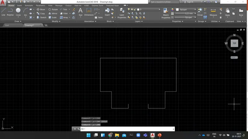
Command: _line
Specify first point:
Specify next point or [Undo]: 10'2"
Specify next point or [Undo]: 10'2"
Specify next point or [Close/Undo]: 9'
Specify next point or [Close/Undo]: 3'
Specify next point or [Close/Undo]: 4'6"
Specify next point or [Close/Undo]: 4'6"
Specify next point or [Close/Undo]: 1'2"
Specify next point or [Close/Undo]:
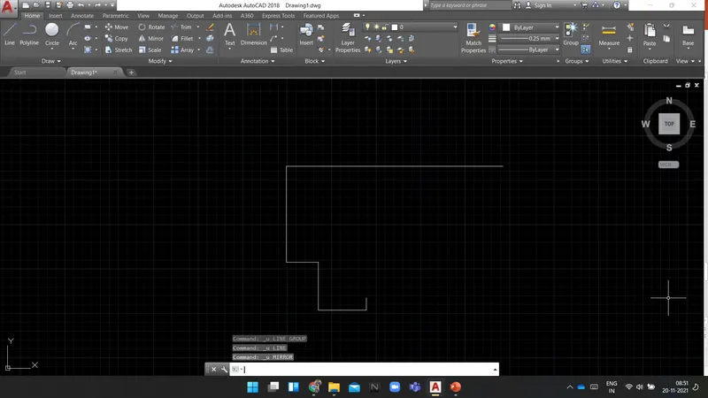
Command: MI MIRROR
Select objects: Specify opposite corner: 5 found
Select objects: Specify first point of mirror line:
Specify second point of mirror line:
Erase source objects? [Yes/No] : n
Command: L LINE
Specify first point:
Specify next point or [Undo]:
Specify next point or [Undo]:
Command:
Command:
Command: _line
Specify first point:
Specify next point or [Undo]: 2'8"
Specify next point or [Undo]:
Command: LINE
Specify first point:
Specify next point or [Undo]: 3'7"
Specify next point or [Undo]:
Command:
Command:
Command: _line
Specify first point:
Specify next point or [Undo]: 6'9"
Specify next point or [Undo]: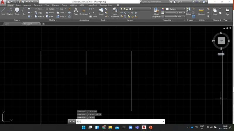
Command: l LINE
Specify first point:
Specify next point or [Undo]: @5'<135
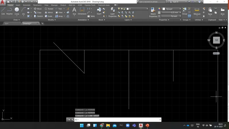
Specify next point or [Undo]:
Command:
Command:
Command: _line
Specify first point:
Specify next point or [Undo]: @5'<120
Specify next point or [Undo]:
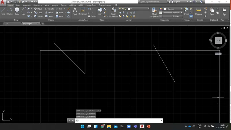
Command: MI MIRROR
Select objects: 1 found
Select objects: Specify first point of mirror line:
Specify second point of mirror line:
Erase source objects? [Yes/No] : n
Command: MIRROR
Select objects: 1 found
Select objects: Specify first point of mirror line:
Specify second point of mirror line:
Erase source objects? [Yes/No] : n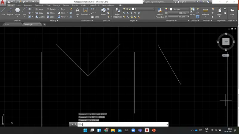
Command: *Cancel*
Command: rec RECTANG
Specify first corner point or [Chamfer/Elevation/Fillet/Thickness/Width]:
Specify other corner point or [Area/Dimensions/Rotation]: d
Specify length for rectangles <20'-0.0000">: 3'
Specify width for rectangles <20'-0.0000">: 3'
Specify other corner point or [Area/Dimensions/Rotation]:
Command: Specify opposite corner or [Fence/WPolygon/CPolygon]:
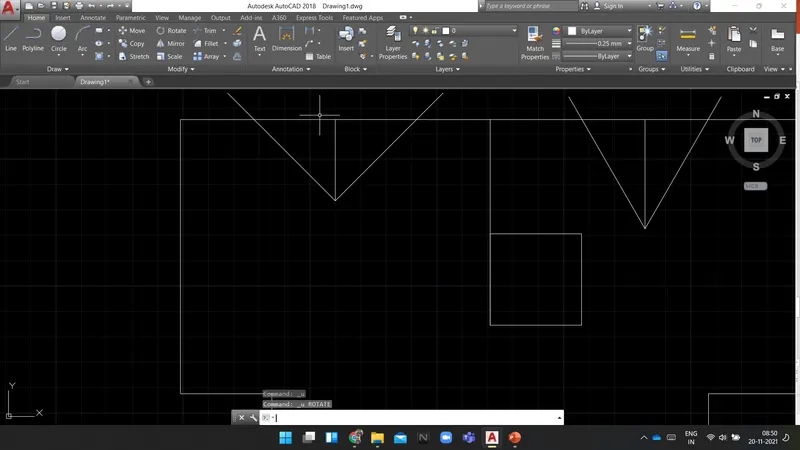
Command: RO ROTATE
Current positive angle in UCS: ANGDIR=counterclockwise ANGBASE=0
Select objects: 1 found
Select objects:
Specify base point:
Specify rotation angle or [Copy/Reference] <45>:
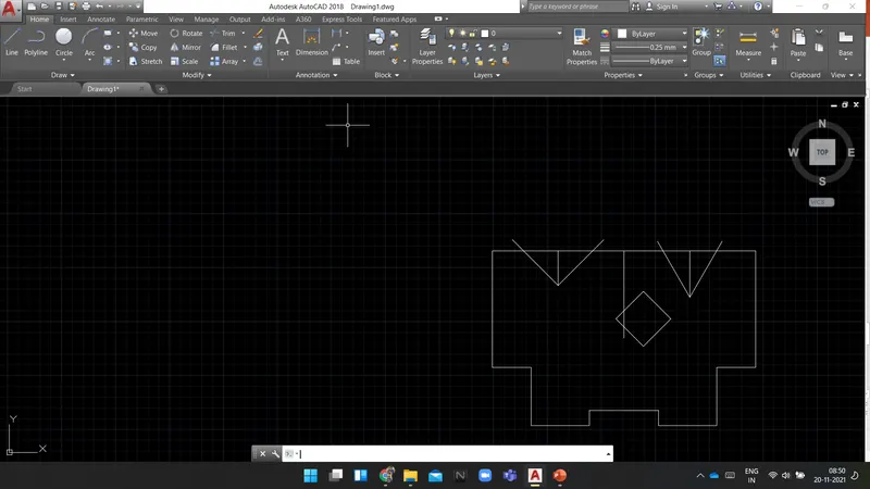
Command: M MOVE
Select objects: 1 found
Select objects:
Specify base point or [Displacement] :
Specify second point or :
Command: MOVE
Select objects: e
*Invalid selection*
Expects a point or Window/Last/Crossing/BOX/ALL/Fence/WPolygon/CPolygon/Group/Add/Remove/Multiple/Previous/Undo/AUto/SIngle/SUbobject/Object
Select objects: 1 found
Select objects: 1 found, 2 total
Select objects: 1 found, 3 total
Select objects:
Specify base point or [Displacement] : *Cancel*
Command: *Cancel*
Command: *Cancel*
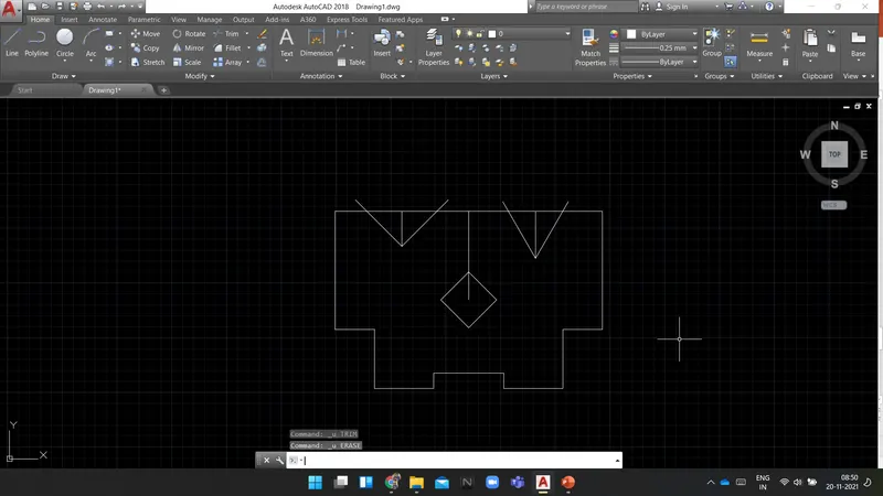
Command: E ERASE
Select objects: 1 found
Select objects: 1 found, 2 total
Select objects: 1 found, 3 total
Select objects:
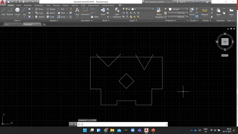
Command: TR TRIM
Current settings: Projection=UCS, Edge=None
Select cutting edges ...
Select objects
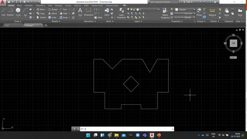
RESULT: The following diagram is drawn using AutoCAD.
----------------------------------------------------------------------------------------------------------------------------------------
----------------------------------------------------------------------------------------------------------------------------------------
----------------------------------------------------------------------------------------------------------------------------------------