Sketch a G+1 residential plan according to Vaastu Shastra and Calculation of Loads as per IS code
Sketch a G+1 floor residential plan, according to vastu shastra, and list down the names of the structural drawings required to be provided to the site for consruction
Also, assume the sizes of the structural elements (Column, Beam, Slab, etc.,) and accordingly calculate the individual corresponding loads from the members as per IS code
Ans:
Aim:
- To sketch a G+1 floor residential plan, according to vastu Shastra, and list down the names of the structural drawing required to be the site for construction
- Also, assume the sizes of the strctural elements ( Column, Beam, Slab, etc.,) and accordingly calculate the individual corresponding loads from the members as per IS code.
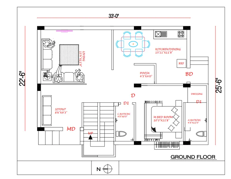
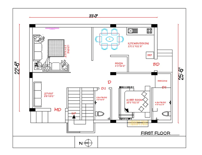
GROUND FLOOR:
- Living Room = 4.67m x 3.35m
- Sit out= 2.48m x 2.74m
- Kitchen Room= 4.57m x 3.55m
- pooja room = 1.34m x 1.21m
- M Bedroom= 3.12m x 3.35m
- Attached Toilet/Bath room= 1.42m x 3.57m
- common toilet/ bath = 1.21m x 2.48m
FIRST FLOOR:
- Living Room = 4.67m x 3.35m
- Sit out= 2.48m x 2.74m
- Kitchen Room= 4.57m x 3.55m
- pooja room = 1.34m x 1.21m
- M Bedroom= 3.12m x 3.35m
- Attached Toilet/Bath room= 1.42m x 3.57m
- common toilet/ bath = 1.21m x 2.48m
Dimensions of structural elements:
- All columns are 300mm x 300m
- Thickness of the exteior wall=230mm
- Thickness of the interior wall=150mm
- All beams are 300mm x 450mm
- Slab thickness if 125mm
- The height of the wall is 4.5m
Indian Standard Codes which I am going to use for load calculations:
- IS456:2000, Revised 2016 for Reinforced Concrete Structure
- IS875-1987, Revised 2018 (Part 1) for Dead Load
- IS875-1987, Revised 2015 (Part 2) for Live Load
- IS875-1987, Revised 2015 (Part 3) for Wind Load
Vastu shastra is the ancient Indian science of architecture and acts as a guidelines to design your home in the way that enhances positive energy.
Basic principles of Vastu Shastra:
- Shape: Rooms should be prefebly be square or rectangle
- Room Basics: Rooms should be airy, well lit, bright and clean
- Home center: Center of the house should be an empty space
- Stair and furniture: Heavy furniture should be kept in the south-west direction
- Water: Avoid keeping plants and water features in the bedroom
- Dining table: Dining space should be near the kitchen and not near the main door
- Mirror placement: Mirror facing the bed is strictly not allowed. Mirrors in the bedroom need to be placed in such a way that the bed cannot be seen
Auspicious directions as per Vastu Shastra:
- Kitchen
South-east is the best
North-east to be avoided
- Staircase:
south-west is the best
North-east to be avoided
- Toilet:
North-west is the best
North-west to be avoided
- Master bedroom:
South-west is the best
- Guest room:
North-west is the best
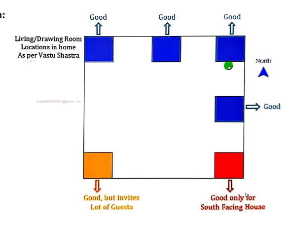
- Living room:
North-west is the best
- Over Head tanks:
West is the best
- Under ground tanks:
North-east is the best
South-west to be avoided
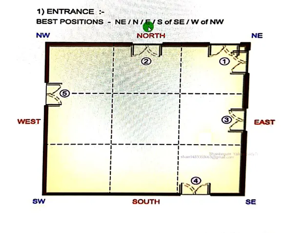
i. Gateway(entrance) of the house:
The main door should be constructed in a way to ensure that when you step out, you face the North, East or in the North-east direction
ii. Living room:
- Living room should face East, North or North-east. North-west facing living room is also favourable
- Heavy furniture should be kept in the West or South-west direction of the living room
- Electronics aplliances should be installed in South-east section of the living room
- If planning for a mirror in this room, ensure you place in North wall
- An aquarium on the North or east wall for prosperity
- A bright picture of sunrise in the south wall
iii. Bed room:
- Bedroom in south-west direction brings good health and prosperity
- Avoid bedroom in North-east a it may cause health issues
- Avoid in South-east zone as it may cause auarrel among couples
- Bed should be kept in South-west corner of the bedroom with head facing west
- Never sleep with your head in the North
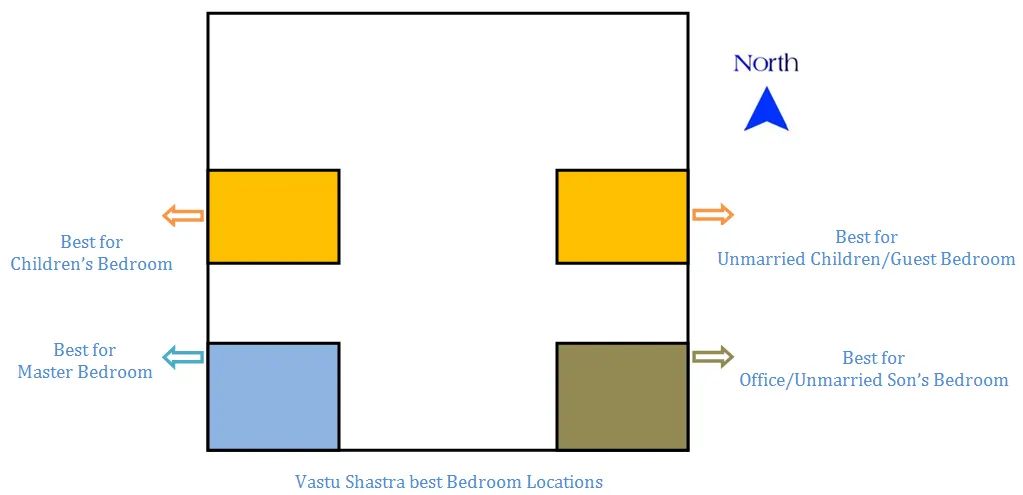
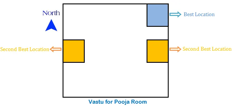
iv. Pooja room:
- East or North-east part of your home is perfect for meditation, Yoga and spiritual pursuits
- Facing East when you meditate will increase positivity
v. Kitchen:
- Keep water sink away from the gas stove
- Fridge needs to be placed at South-West corner
- Never let your kitchen face a wshroom wall nor share a common wall with it
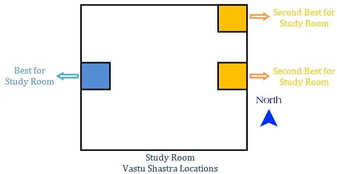
vi. Study Room:
- Slect a square or rectangle shape for the study table
- Placing a table in North-east, East or West direction is ideal
vii. Courtyard:
- Brahmasthan is a unique feature of ancient Architecture based on Vastu shastra
- It is the center of your residence and the holiest and most powerful zone

List of grawings that is mandatory to be provided to the site are:
I. Center line drawing
- It is used for the marking of the columns at the site during first stage where soil is excavated for the footings
- It contains all the grid positions and column demensions and numbering (provided outside of column)
- It is a important which is first issued to the site
- Grid to grid distance and structural notes and the legends are mandatory
II. Footing and column layout with reinforecement details:
- It shows the size and dimensions of the footing from center of the columns and also with reference to the gridlines
- Here we can check weather there is a footing clash from which we can manage by altering the dimension is required directions so there is no clash obtained
- Grid to grid distance and structural notes and the legends are mandatory
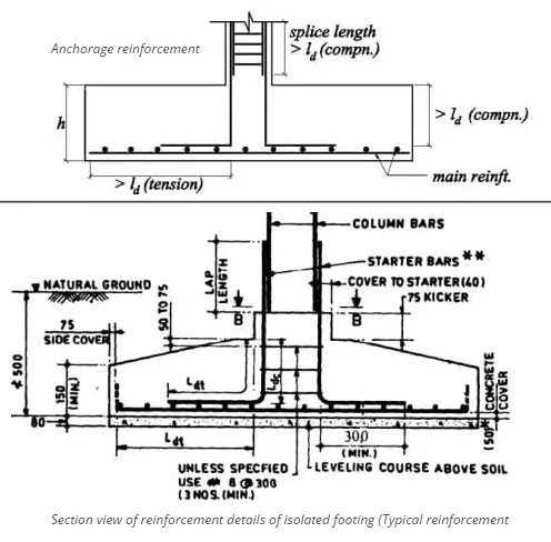
III. Column schedule with reinforcement:
- Typical footing layout details are provided
- Reinforcement details of the column is required
- For respective columns provided the column size and column reinforcement detail and strirrups details is also to be provided
- Footings also has to be categorized
IV. Plinth beam layout with reinforcement details:
- Provide the column that are connected to the soil at the plinth level
- Specify all PB footings which describes the reinforcement of the plinth beam
- Numbering and grouping of the PB are important step
- 2 bars at both top and bottom reinforcement are mandatory
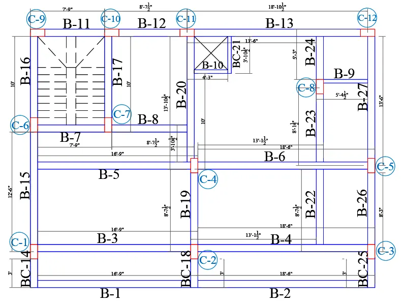
V. First floor beam layout with reinforcement details:
- Any details of the floating column
- Where the typical beams connecting the columns
- Beam numbering and grouping is shown
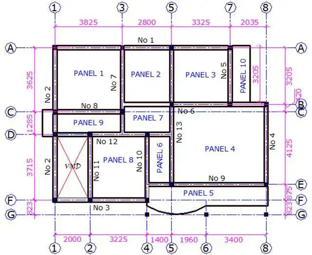
VI. First floor Slab layout with reinforcement details:
- Provide the location of the sunken slab with its sunken thickness
- Floor beams and slab dimensions are provided commonly
- Level Difference if required should be presented
- Reinforecement details of the slab is must
- Crank position should be indicated
- Details of the main and distribution reinforcement
- Where the typical beams connecting the columns
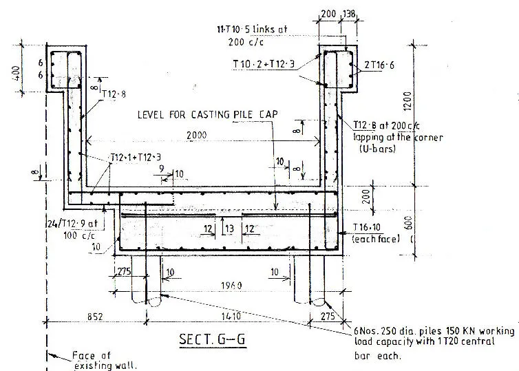
VII. Lift pit and headroom reinforcement details:
- It covers the area of the lift pit area describing the thickness of the RCC wall and waterproof wall
- And provision of the lintel beam is mandatory
- Sectional view of the lift pit is also important
- Lift pit and headroom should be in same position
- Load should be considered before the liftroom
GROUND FLOOR :
I) Dead load of Calculation:
1. Column= (300mm x 300mm)
Dead load of column= Self weight of column
Column height= Height of wall + Slab thickness= 4.5+0.125= 4.625m
Column Size= 0.30m x 0.30m x 4.625m =0.4162m3
Unit weight of concrete (RCC)= 25 KN/m3
Dead Load of column= Total volume of concrete x Unit weight of concrete
= 0.4162 m3 x 25 KN/m3=10.40KN
Dead load of column= Self weight of column=10.46KN
As per design, 9 number of columns are provided
2. Beam= (300 x 450)
Beam Size= 0.3m x 0.45m
We will calculate, load in the form of UDL
Unit weight of concrete(RCC)=25KN/m3
Dead load of Beam= Beam size x Unit weight of concrete
=0.3 x 0.45 x 25
Dead load of Beam = 3.38KN/m
3. Exterior Wall load on beam:
Wall load on beam= Dead load of wall
Height of the wall=4.5m
Thickness of the exteior wall=230mm=0.23m
Unit weight of brick wall = 20KN/m3
Dead load of wall= (Height of wall x Thickness of the exterior wall) x Unit weight of brick wall
= 4.5 x 0.23 x 20
Exterior Wall load on beam= 20.7KN/m
4. Interior Wall load on beam:
Wall load on beam= Dead load of wall
Height of the wall=4.5m
Thickness of the interior wall=150mm=0.15m
Unit weight of brick wall = 20KN/m3
Dead load of wall= (Height of wall x Thickness of the exterior wall) x Unit weight of brick wall
= 4.5 x 0.15 x 20
Exterior Wall load on beam= 13.5KN/m
5. Self weight of slab:
Self weight of slab=Dead load of load
Thickness of slab=125mm=0.125m
Self weight of RCC slab= thickness of slab x Unit weight of RCC
= 0.125 x 25=3.125KN/m2
6. Self weight of ceiling: 0.25KN/m2 (As per IS 875 Part 1)
7. Self weight of roofing= 0.83Kn/m2 (As per IS 875 Part 2)
8. Floor Finish=1KN/m2
II) Live Load Calculation:
- Living Room = 4.67m x 3.35m =15.64m
- Sitout= 2.48m x 2.74m =6.79m
- Kitchen = 4.57m x 3.55m = 16.22
- pooja room = 1.34m x 1.21m = 1.62m
- M Bedroom= 3.12m x 3.35m = 10.45m
- Attached Toilet/Bath room= 1.42m x 3.57m =5.06m
- common toilet/ bath = 1.21m x 2.48m =3.00m
| S.Nor | Building units |
Load as per IS code in UDL KN/m2 |
Area in m2 |
Live load in KN |
| 1 | Living Room | 2 KN/m2 | 15.46 | 30.92 |
| 2 | sitout | 2 KN/m2 | 6.79 | 13.58 |
| 3 | Kitchen | 2 KN/m2 | 16.22 | 32.44 |
| 4 | pooja room | 2 KN/m2 | 1.62 | 3.24 |
| 5 | M Bedroom | 2 KN/m2 | 10.45 | 20.9 |
| 6 | Attached toilet/bath room | 2 KN/m2 | 5.06 | 10.12 |
| 7 | common toilet/bath | 2 KN /m2 | 3 | 6 |
| 8 | Staircase | 3 KN/m2 | 9.2 | 27.6 |
III) Wind Load Calculation:(IS 875 PART 3)
- Wind load shall be considered when the building height exceeds the 10m
- Here, the building height is less than 10m hence, wind load calculation is ignored
Wind Loads
When the height of a building is more than 10m, the building needs to be designed for wind Load. These horizontal loads are caused by wind acting on the structure. Wind load acts horizontally towards walls and roof surface.
Calculation Procedure:
Step 1: Calculate the Design Wind Speed (Vz)
Vz=Design wind speed at height z, in m/s
= vb x k1 x k2 x k3 x k4
Where Vb, k1, k2, k3 and k4 are as described below
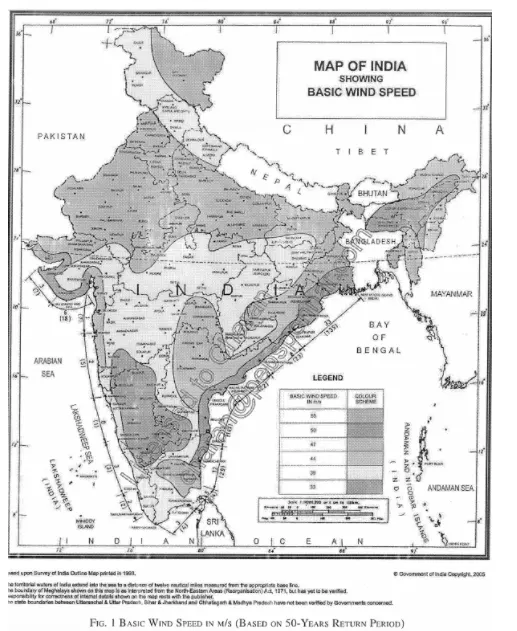
- Basic Wind Speed (Vb)
The basic wind speed can be taken from figure 1 of IS 875 part III entitled Basic Wind Speed in m/s ( Based on 50- years return period). the wind speed varies between 55, 50, 47, 44, 39 and 33 m/s depending on its location within the given map.
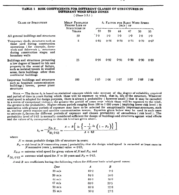
- Probability factor / Risk Coefficient(k1)
This value can be taken from table 1 risk Coefficient For Different Classes of Structures in Different Wind Speed zones. In the design of buildings and structures, a regional basic wind speed having a mean return period o 50 years shall be used except as specified in the note of Table 1. In the table the values for k1 is determined by the class of the structure and its life span in years
- Terrain Height Factor(k2)
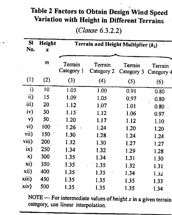
This value can be taken from table 2 factors to obtain Design Wind Speed Variation with height in different terrains. This factor is divided into 4 categories:
- Topography Factor(k3)
The effect of topography shall be significant at a site when the upwind slope is more than 3 degree, and below that, k3 value may be taken as 1.0. k3 value ranges from 1.0-1.36 for upwind slope greater than 3 degree. It varies with height above grund level, at a maximum near the ground, and reducing to 1.0 at higher levels. for evaluating the value of k3 greater than 1.0 refer to appendix C of IS 875 part 3
- Importance Factor for the Cyclonic Region (k4)
As stated in clause 6.3.4 of IS 875 part 3 studies of wind speed and damage to buildings and structure point to the fact that the speed given in the basic wind speed map are often exceeded during the cyclones. The effect of cyclonic storms is largely felt in a belt of approximately 60km width at the coast. In order to ensure better safety of structure in regions prone to cyclones, the following values of k4(as recommended in IS 15498) are stipulated as applicable according to the importance of the structure:
- Structure of post-cyclonic importance for emergency services (such as cyclone shelters, hospitals, schools, communication tower, etc) ; k4 = 1.30
- Industrial Structure ;k4=1.15
- All other structures ; k4=1.00
Step 2: Calculate Wind pressure(Pz)
Pz= Design pressure at height z. in N/m2
= 0.6 Vz^2
Where Vz is the design wind speed described in step 2
Step 3: Calculate Design Wind Pressure (Pd)
Pd=Design wind pressure, in N/m2
= Kd x Ka x Kc x Pz
Pd shall not be taken as less than 0.7 Pz
Where Pd is taken from step 2 while Kd, Ka, and Kc are described below
- Kd is described in clause 7.2.2 As the area becomes larger, the correlation of measured values decrease and visa-versa. the decrease in pressure due to larger areas may be taken into account as given in table 4 Area Averaging Factor(Ka)
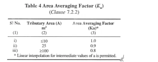
The tributary are is divided into two as described in Clause 7.2.2.1
-Overall structure- for evaluating loads on frames, the tributary area shall be taken as the centre to entre distances between frames multiplied by the individual panel dimension in the other direction together with overall pressure coefficients
-Individual Elements- For beam type elements, purlins, etc, the tributary area shall be taken as effective span multiplied by spacing. The effective span is the actual span for mid span and cantilever load effects; and half the sum of adjacent spans for support moments and reactions
- Combination Factor (Kc)
This factor is described in clause 7.3.3.13. When taking wind loads on frames of clad buildings, it is reasonable to assume that the pressures or suctions inside and outside the structure shall not be fully correlated. Therefore when taking the combined affect of wind loads on the frame, a reduction factor of Kc= 0.9 may be used over the building envelope when roof is subjected to pressure and internal pressure is suction, or vice-versa
Step 4 : Calculate the Wind Load on Individual Members(F)
the formula for the wind load on individual members is taken from Clause 7.3.1
F=(Cpe-CPi) A Pd
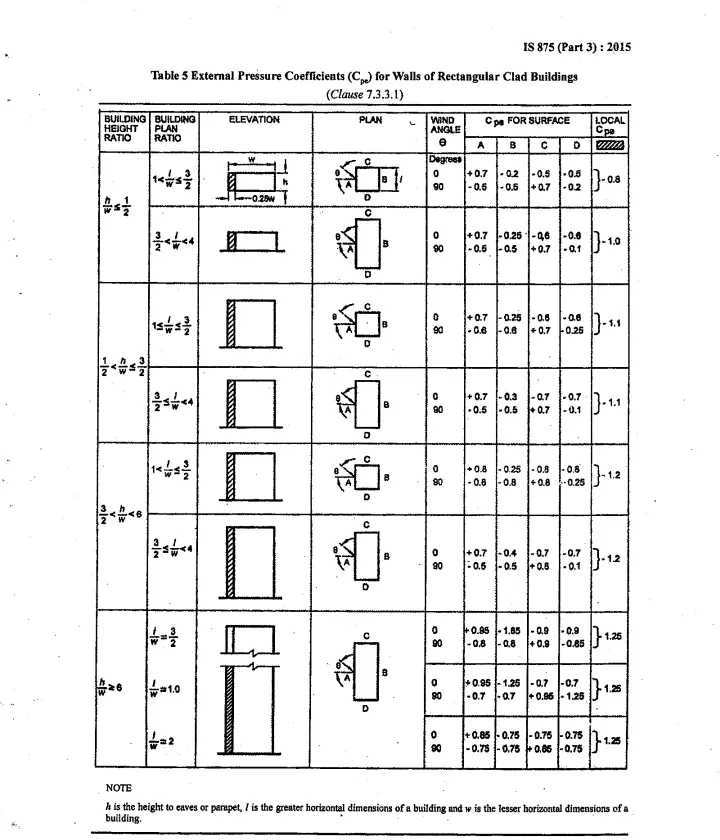
- The extrnal pressure coefficient for a Monoslope steel building can be taken from table 5 (for walls) and table 7 (for the monoslope roof). the monoslope angle is used to determine the Cpe coefficient together with the wind angle
For External Pressure Coefficient of walls
Table 5 of IS 875 Part 3 is used. The height to width ratio is used to determine what case to be used. Furthermore, the building plan ratio (l/w) is taken into account.
- Internal Pressure Coefficient (Cpi)
The internal pressure coefficient is described in clause 7.3.2 The internal pressure coefficient can be taken as one of the values below:
- +0.2/-0.2; where the claddings permit the flow of air with open buildings not more than 5% of the wall area but there is no large openings
-+0.5/-0.5 ; Buildings with medium openings about 5 to 20% of wall area
-+0.7/-0.7 ; Building with large openings larger than 20% of the wall area
- Surface Area of Structural Element or Clading Unit (A)
This will be calculated based on the dimension given. It is a simple length x width where length and width is taken from calculated dimensions
NOTE: As the size are same for the first floor so all load calculation are same as ground floor load calculation