Drafting of various geometries using Chamfer, Fillet tool in AutoCad
1. Aim and introduction
Aim:
This challenge aims to provide deeper understanding about using the different tools in the Autocad software. It focuses on tools such as "Fillet", "Chamfer", "Rectangle", "Circle", "Trim" and many more.It shows that by using the Autocad software, various shapes can be sketched once you have the knowledge on how to proceed with different shapes.The challenge consists of 2Dgeometrics in differents shapes and sizes. It also aims to know the various types of dimensions used in AutoCAD.
Introduction:
The AutoCAD software provides different tools. The tools used in this challenge is as described below:
Line- creates line object
Rectangle- creates rectangles object
Circle- create circle object
Trim-Cut unwanted lines or shapes with the provided cutting edges
Extended- Extend lines to opposite corners
Move- Move objects to particular locations
Copy- Copy obejects to particular locations
Rotate- Rotate selected objects to a particular angle with respect to base point
Dimlinear(DLI)- provides vertical or horizontal linear/ straight dimensions
Dimligned(DAL)- Provides dimensions with respect to the angle of the object
Dimangular(DAN)- Provides angular dimensions between two line objects.
2. Sketch and procedure:
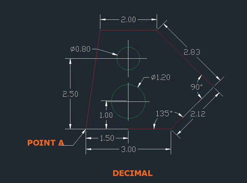
A SKETCH 1: Decimal
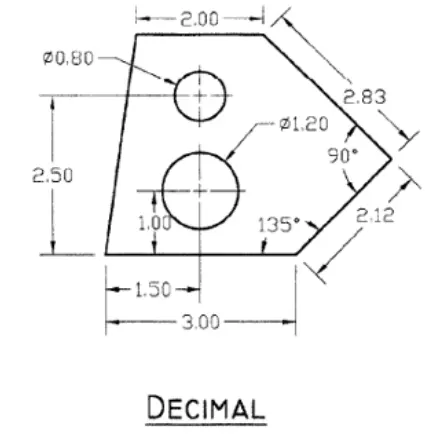
procedure:
- Create boundary element, Select "Line " tool
- Specify first point: Any point (Point A)
- Specify next point:@3<0
- Specify next point:@2.12<45
- Specify next point:@2.83<135
- Specify next point:@2<180
- End: close
- Create big circle, Select "Circle" tool
- Specify center point: Point A
- Select"D", Specify diameter:1.2, End
- Select Circle object
- Slect the move tool
- Specify base point: Point A
- Specify second point:1.5, 1
- Create small circle, select "circle" tool
- Specify center point: Point A
- Select"D", Specify diameter:0.8, End
- Select Circle object
- Slect the move tool
- Specify base point: Point A
- Specify second point:1.5, 2.5
For the dimensions, the Decimal type is used
To Change the dimension type, the steps below are followed:
- Open " Dimension style Manager", type "Dimenstyle" in the command prompt and press enter.
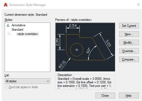
- Select modify. A new window will appear
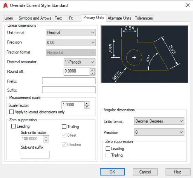
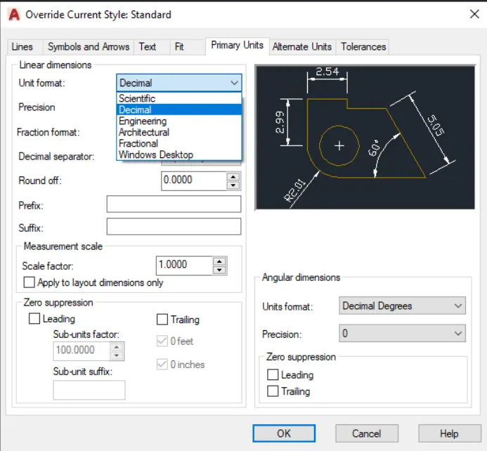
- Go to "Primary tnits", change the "Unit Format" to "Decimal" type
- Then press "Ok"
Final drawing:
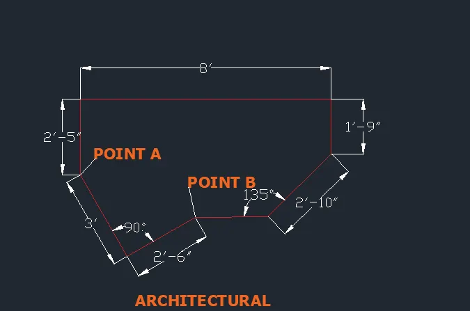
B. SKETCH 2: Architectural
PROCEDURE:
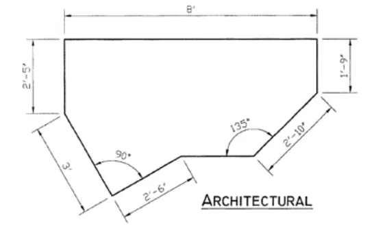
Note: Architectural units are used. 1 feet (1') is equal to 12 inches (12")
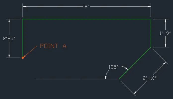
- Create straight elements, Select "Line " tool
- Specify first point: Any point (Point A)
- Specify next point:@29<90
- Specify next point:@96<0
- Specify next point:@21<270
- Specify next point:@34<-135
- Specify last point: Any distance to the left (Straight line)
- Product should be as below
- Create the next, Select "Line " tool
- Specify first point:Point A
- Specify next point:@36<270
- Specify last point: @30<0, End, Set as point B
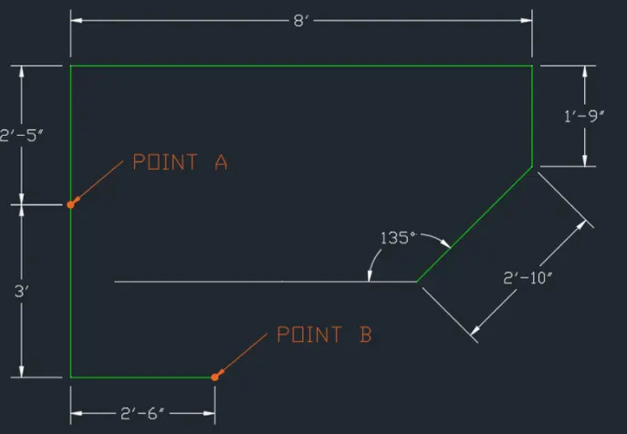
- Create Circle object for reference, Select "Circle" tool
- Specify first point: Point A
- Specify radius: Point B
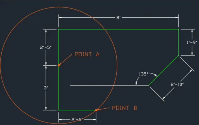
- Rotate the last 2 lines created to the correct position. Select the last 2 created lines
- Select"Rotate" tool
- Specify base point: Point A
- Select "Reference"
- Specify reference angle, first point: Point A
- Specify second point: Point B
- Specify new angle: Intersection point between circle and horizontal white line
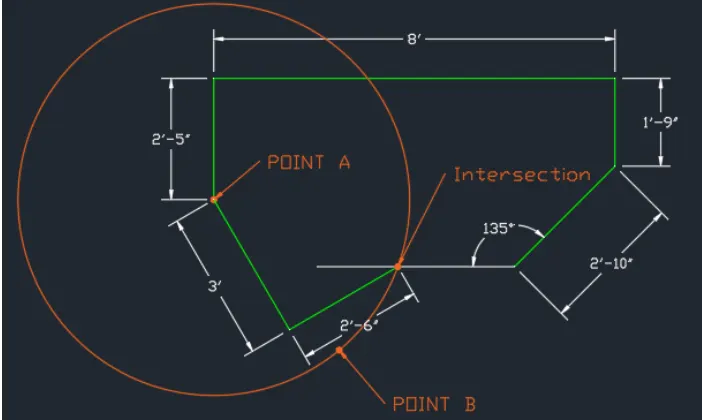
- To delete ectended line, select "Trim" tool
- Select cutting edges: Line object. then press "enter"
- Selct object to trim: Extended white line
- To finish the challenge, delete the circle object by using "Erase" tool or just select the object and press the "Delete" button
For the dimensions, the Decimal type is used
To change the dimension type, the steps below are followed:
- Open " Dimension style manager", type "dimenstyle" in the command prompt and press enter
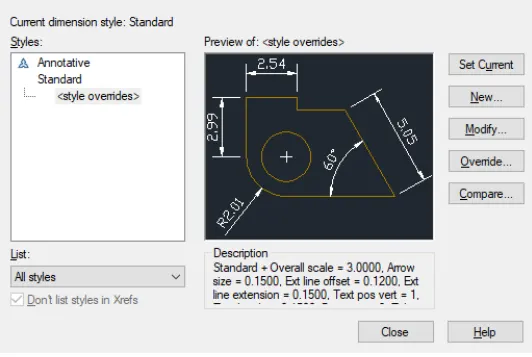
- Select modify. A new window will appear
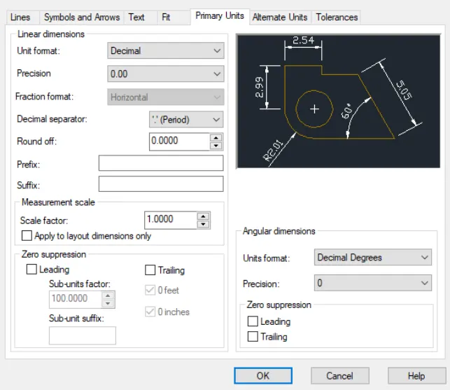
- Go to "Primary units", change the "unit Format" to "Architectural" type
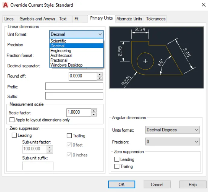
- Then press "OK"
C.SKETCH3: ENGINEERING
PROCEDURE:
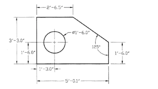
Note: Engineering units are used. 1feet is equal to 12inches
- Create boundary element, Select "Rectangle) tool
- Specify first corner point: Any point (Point A)
- Specify second corner point: 60.01,39
- To create the cut part, select "Chamfer" tool
- Select "Distance"
- Specify first chamfer distance: 29.6
- Specify second chamfer distance:21
- Specify first line: Upper line of rectangle
- Specify second line: right line of rectangle
- Now create the circle object inside, select circle tool
- Specify center point: Point A
- Select "Diameter"
- Specify diameter of circle:18
- Now let us move thecircle to the correct position. select the created circle object
- Specify "Move" tool
- Specify base point:Point A
- Specify second point: 15,18
For the dimensions, the Decimal type is used
To change the dimension type, the steps below are followed:
- open Dimension style manager, type Dimstyle in the command prompt and press enter
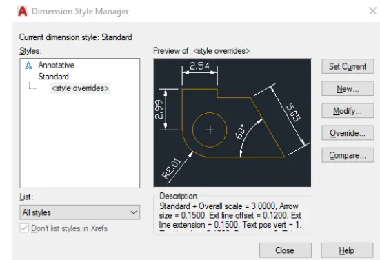
- Select modify. A new window will appear
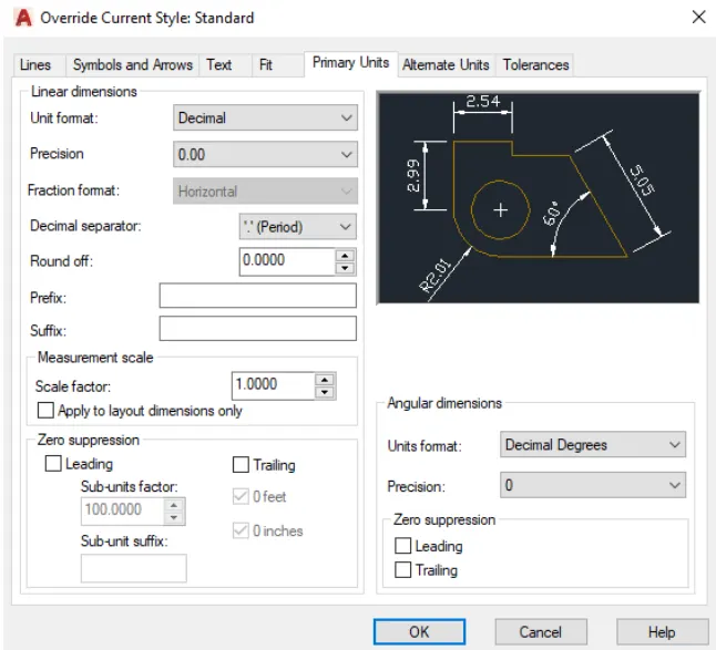
- Go to primary units, change the unit format to engineering type
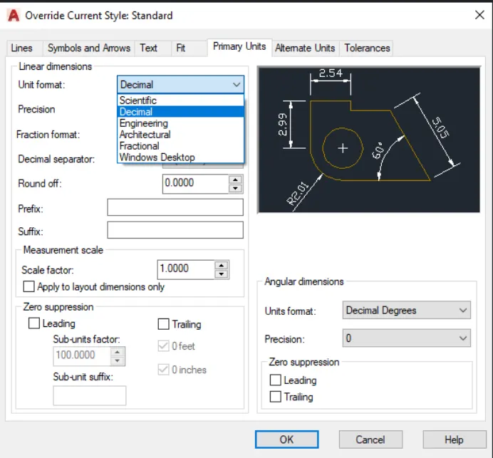
- Then press OK.
FINAL PRODUCT:

C.SKETCH 4:
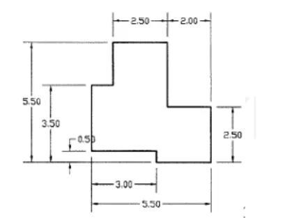
PROCEDURE:
- Create boundary Object element, Select "Rectangle" tool
- Specify first corner point: Any point (Point A)
- Specify second corner point: @5.5,5.5
- Set upper left corner as Point B
- Select upper right corner as Point C
- Create 3 extra rectangle object. Create first rectanglr object. Select rectangle tool.
- Specify first corner point: Any point (Point A)
- Specify second corner point: @3.0,0.5
- Create second rectangle object. Select rectangle tool
- Specify first corner point: Any point (Point B)
- Specify second corner point: @1.0,-2.0
- Create third rectangle object. Select rectangle tool
- Specify first corner point: Any point (Point C)
- Specify second corner point: @-2.0, -3.0
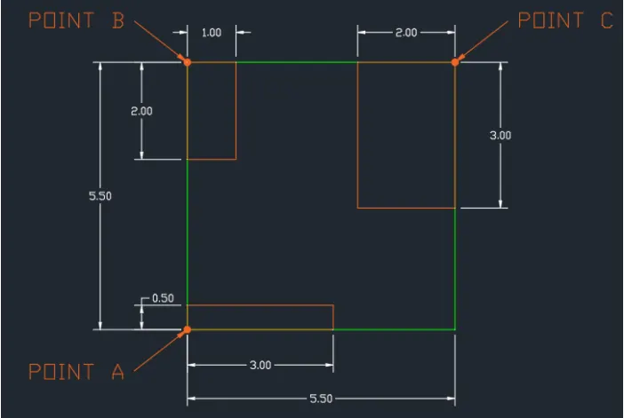
- Use thectrim tool to delete the unwanted lines
- Select Trim tool
- Seelct cutting edges: press "enter" to select all as cutting edges
- Select "fence" or just select the edges to be trimmed
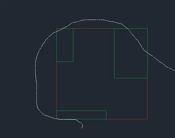
FINAL PRODUCT:
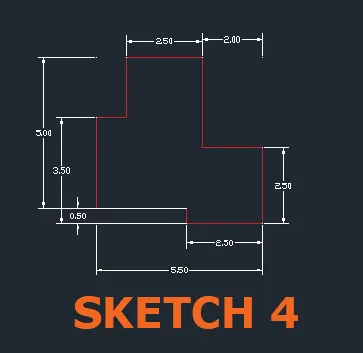
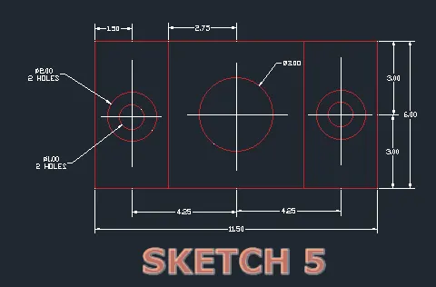
E. SKETCH 5
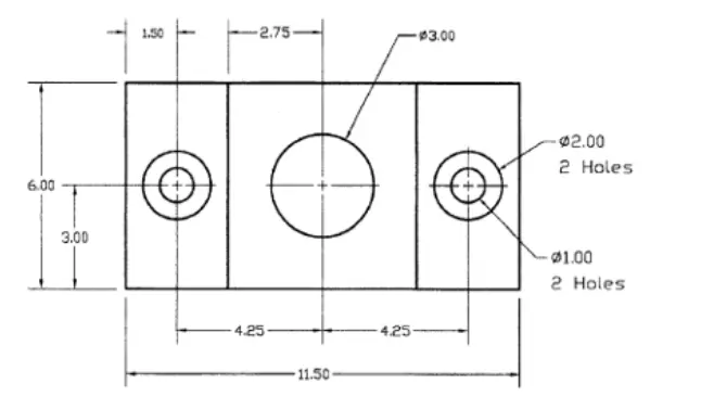
PROCEDURE:
Note: Snap tool will be usec to find the "Endpoint", "Midpoint", and "Center of circle" of the lines.
To turn on snap tools, type "ds" in the command prompt. The "Drafting Setting" window will appear. Go to the "Object Snap" tab and click the corresponding "Object Snap Modes" to turn it on.
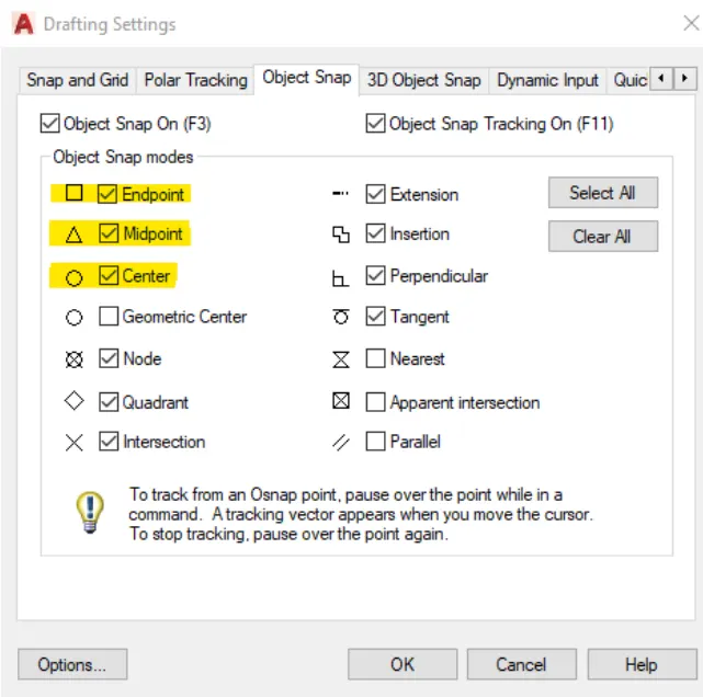
- Create boundary line and reffrence line (White line- shown in image below, after procedure)
- Select "Rectangle" tool
- Specify first corner point:any point
- Specify second corner point:11.5,6
- Select "Line" tool
- Specify first point: Midpoint of upper line of rectangle
- Specify next point: Midpoint of lower line of rectangle
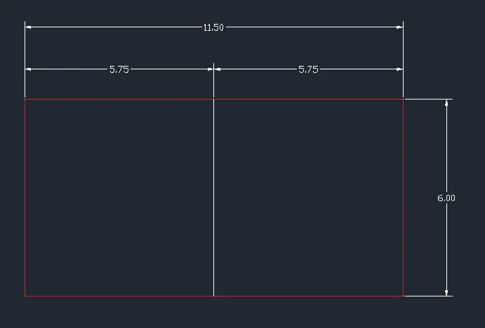
- Now create the 2 vertical lines nad circle. select the reference line object
- Select "copy" tool
- Specify base point:Any point within the reference line, example: Midpoint
- Specify second point: "Right", 2.75
- Specify second point: point "Left", 2.75
- Select "Circle" tool
- Specify center point of circle: Midpoint of reference line
- Slect "Diameter"
- Specify diameter of circle: 3
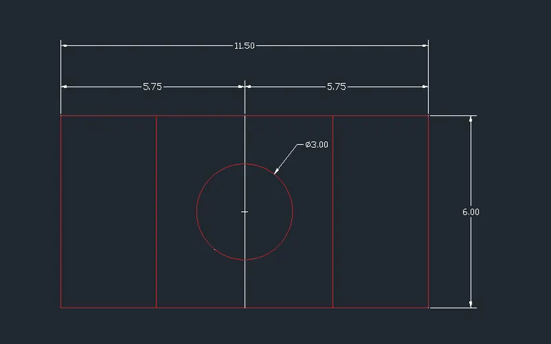
- Now we can create the reference line and create the 2 circles. select the reference line object
- Select "Erase" tool and press enter or press delete button.
- Select "Circle" tool
- Specify center point of circle: Midpoint of the right vertical line
- Slect "Diameter"
- Specify diameter of circle: 1.0
- Select "Circle" tool
- Specify center point of circle: Midpoint of right vertical line
- Slect "Diameter"
- Specify diameter of circle: 2.0
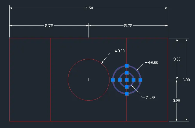
- Now move the 2 circles to right by 1.5 units. Select the 2 circle object
- Select "move" tool
- Specify base point: Center of circle
- Specify second point:point"Right", 1.5
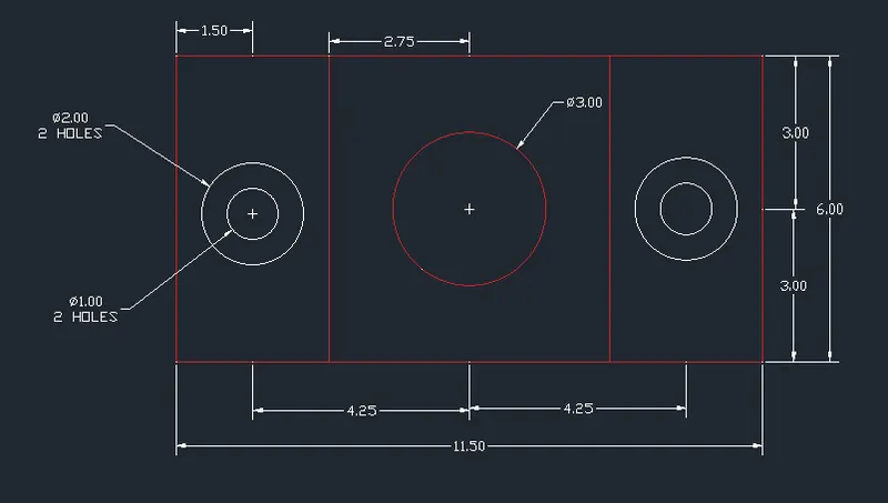
- Now let us mirror the 2 circles to finish the sketch. Select the two circle objects
- Selet "mirror" tool
- Specify first point of mirror lines: Midpoint of the upper line of rectangle
- Specify second point of mirror line: Midpoint of thel ower line of rectangle
- Erase source object :No
FINAL PRODUCT:
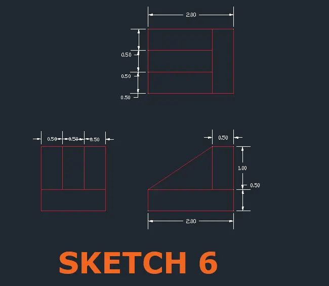
F. SKETCH 6
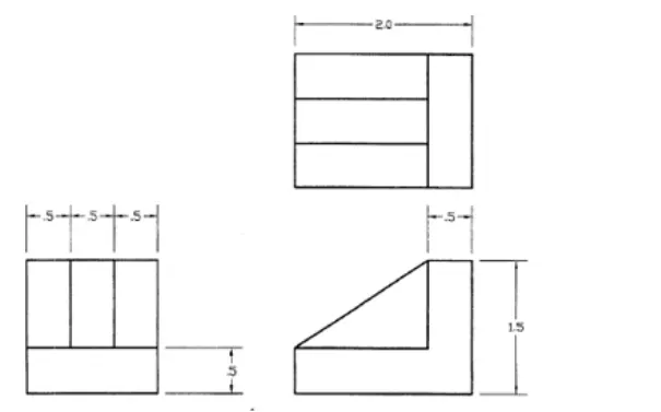
PROCEDURE:
For this sketch, we create the lower left drawing first, followed by the lower, and finish with the upper right object
- Select "Rectangle" tool
- Specify first corner point:any point
- Specify second corner point:1.5,0.5
- Select "Rectangle" tool
- Specify first corner point:Upper left corner of first rectangle
- Specify second corner point:0.5, 1.0
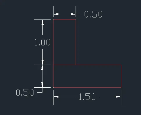
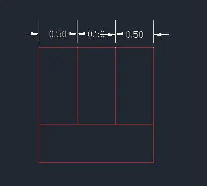
- Complete thecfirst sketch by using copy tool. Select the second rectangle object
- Select "copy" tool
- Specify base point: Lower left corner of second rectangle
- Specify second point:Lower right corner of second rectangle
- Specify second point:Lower right corner of newly created(third) rectangle
- Proceed to the second sketch. Make sure that the sketch is align using the tracking tool
- Select "Rectangle" tool
- Specify first corner point: Any point at the right side of the lower right corner of the first rectangle. use tracking to make sure it is aligned
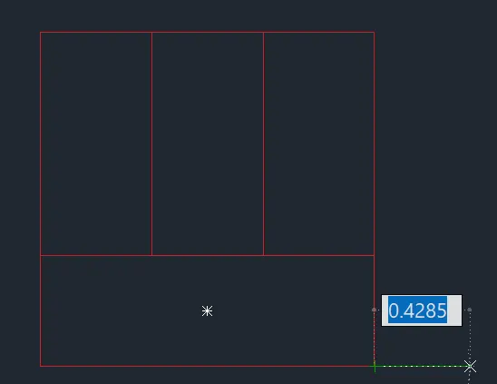
- Specify second corner point: 2.0,0.5
- Select "Rectangle" tool
- Specify first corner point: Upper right corner of newly created rectangle
- Specify second corner point:-0.5,1.0
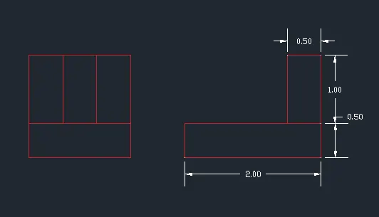
- To delete the lines between the two rectangles, use the "trim" tool. Select "trim" tool
- Select cutting edges: select the two rectangles or just press enter
- Slect object to trim: Select the line to be trimmed
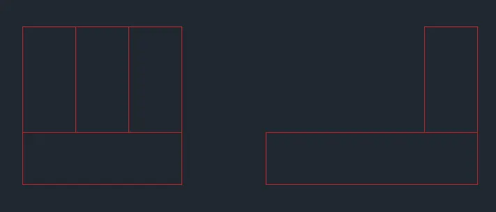
- Now connect the corners using the line tool
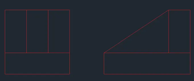
- Proceed to the second sketch. Make sure that the sketch is align using the tracking tool
- Select "Rectangle" tool
- Specify first corner point: Any point at the upper side of the upper right corner of the second sketch. Use tracking to make sure it is aligned.
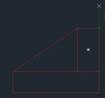
- Specify second corner point:-0.5,1.5
- Select "Rectangle" tool
- Specify first corner point: Upper left corner of newly created rectangle
- Specify second corner point:-1.5,0.5
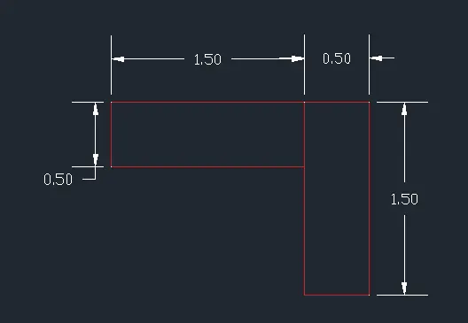
- To finish sketch 3, copy the latest triangle. Select the latest triangle.
- Specify base point:Upper right corner of upper left rectangle in sketch 3.
- Specify second point:Lower right corner of rectangle
- Specify second point:Lower right corner of newly created rectangle
FINAL PRODUCT:
G. SKETCH 7:
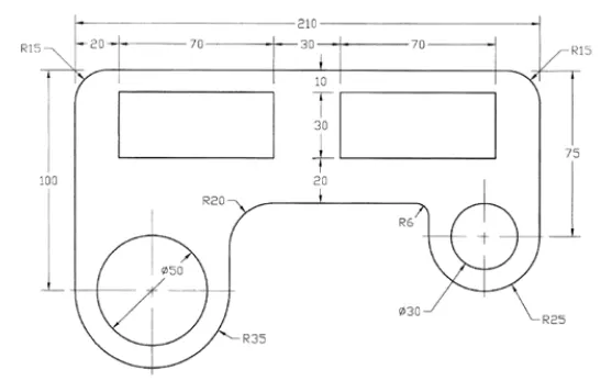
PROCEDURE:
- Create three rectangles. Select "Rectangles" tool
- Specify first corner point:Any point
- Specify second corner point:210,60
- Select "Rectangle" tool
- Specify first corner point: Lower left corner of first rectangle
- Specify second corner point:70,-75
- Select "Rectangle" tool
- Specify first corner point: Lower right corner of first rectangle
- Specify second corner point:-50,-40
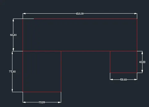
- Now trim the unrequired lines. Select "trim" tool
- Press "Enter" to select all as cutting edges
- Select object to trim: Select the lines to be deleted
- Create the inside objects. First corner points are specified in the image below
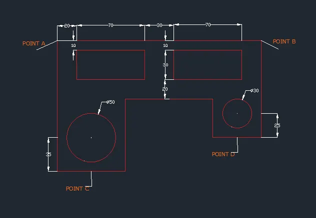
- Create upper left rectangles. Select "Rectangle" tool
- Specify first corner:Point A
- Specify second corner point:70,-30
- Now move the created rectangle. Select the rectangle
- Specify base point:Point A
- Specify second point:20,-10
- Create upper right rectangles. Select "Rectangle" tool
- Specify first corner:Point B
- Specify second corner point:70,-30
- Now move the created rectangle. Select the rectangle
- Specify base point:Point B
- Specify second point:20,-10
- Create lower left circle. Select "Circle" tool
- Specify center pooint:Point D
- Select "Diameter"
- Specify diameter of circle:30
- Now move the created circle. Select the circle
- Specify base point:Point D
- Specify second point:0,25
Now fillet the edges
- Fillet upper left corner. Select "Fillet" tool
- Select "Radius"
- Specify radius:15
- Select first object: Left line
- Select second object: Upper line
- Fillet upper right corner. Select "Fillet" tool
- No need to specify radius
- Select first object:Right line
- Select second object:Upper line
- Fillet lower left side (Containing big circle). Select "Fillet" tool
- Select "Radius"
- Specify radius:35
- Select first object: Left line
- Select second object: Lower line
- Fillet right side. Select "Fillet" tool
- No need to specify radius
- Select first object:Right line
- Select second object:lower line
- Fillet lower left side (Containing big circle). Select "Fillet" tool
- Select "Radius"
- Specify radius:25
- Select first object: Left line
- Select second object: Lower line
- Fillet right side. Select "Fillet" tool
- No need to specify radius
- Select first object:Right line
- Select second object:lower line
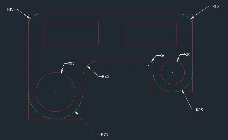
FINAL PRODUCT:
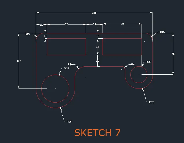
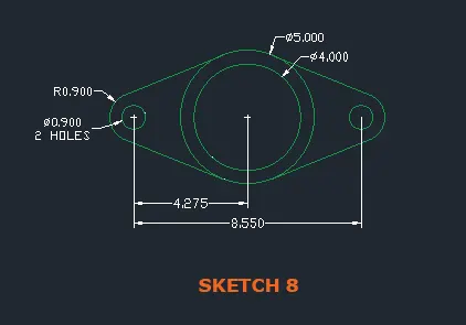
H. SKETCH 8:
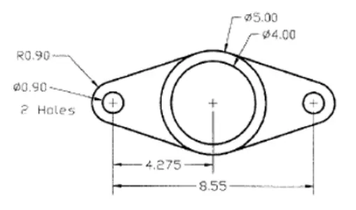
- Make three points for the centers of the circle. Select "Point" tool
- Specify point: Any point
- Copy point to the right. Select point object
- Make sure Ortho mode is on. Select "copy" tool
- Specify base point: the point itself
- Specify second point: Point "Right", 4.275
- Specify second point: Point "right", 8.55
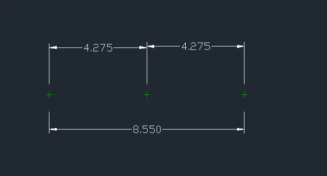
- Create the side circles. Select "Circle" tool
- Specify center point: left point
- Select "Diameter"
- Specify diameter of circle:0.9
- Select "Circle" tool
- Specify center point: Left point
- Select "diameter"
- Specify diameter of the circle: 1.8
- Select the two created Circle objects
- Select "copy" tool
- Specify base point: Left point
- Specify second point:Right point
- Create the middle circles. Select "Circle" tool
- Specify center point: middle point
- Select "Diameter"
- Specify diameter of circle:4.0
- Select "Circle" tool
- Specify center point: middle point
- Select "diameter"
- Specify diameter of the circle: 5.0
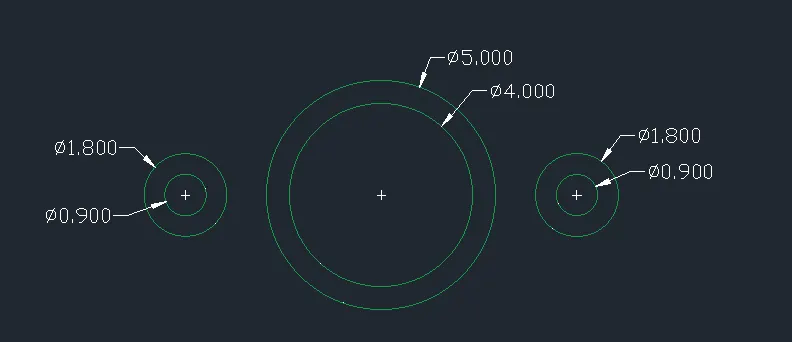
- Create the tangent lines on the left side. Select "Line" tool
- Type "Tan" or "tangent" to proc the tangent snap tool
- Specify first point: Upper left side of left circle
- Specify second point: Upper left side of middle circle
- Select "Line" tool
- Type "Tan" or "tangent" to proc the tangent snap tool
- Specify first point: Lower left side of left circle
- Specify second point: Lower left side of middle circle
- Create the tangent lines on the right side. Select "Line" tool
- Type "Tan" or "tangent" to proc the tangent snap tool
- Specify first point: Upper left side of left circle
- Specify second point: Upper left side of middle circle
- Select "Line" tool
- Type "Tan" or "tangent" to proc the tangent snap tool
- Specify first point: Lower right side of left circle
- Specify second point: Lower right side of middle circle
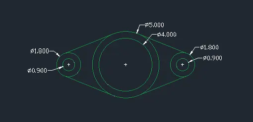
FINAL PRODUCT:
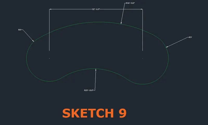
I. SKETCH 9:
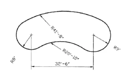
PROCEDURE:
Note: Engineering units are used. 1feet is equal to 12 inches
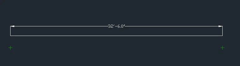
- Create two Specify a point: Any point
- Select point object
- Specify base point: The point itself
- Make sure Ortho mode is on. Specify second point: Point "Right", 390
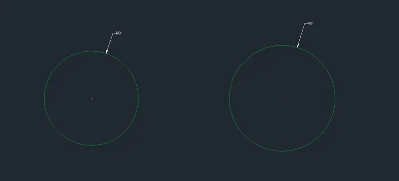
- Create the circles. Select "circle" tool
- Specify center of circle: Left point
- Specify radius:96
- Select "Circle" tool
- Specify center of circle: Right point
- Specify radius:108
- Create lower tangent line using the fillet tool
- Select "fillet" tool
- Specify radius:250
- Select "Circle" tool
- Select first object: lower part of left circle
- Select second object: lower part of right circle
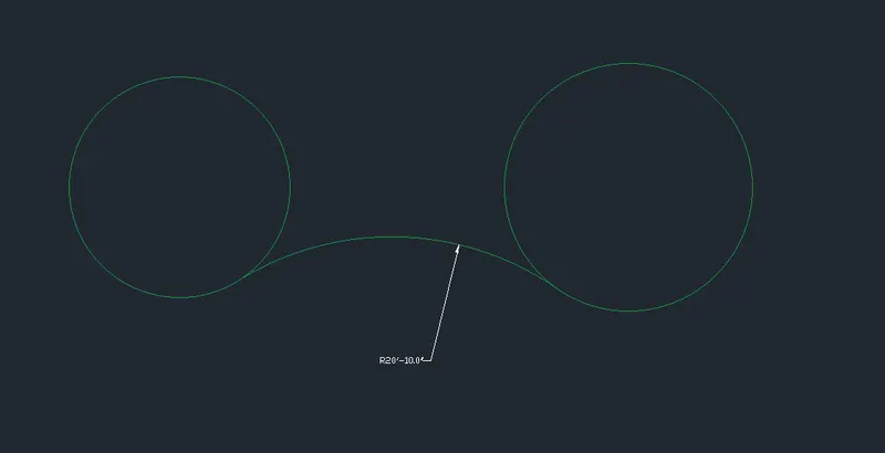
- Now create a circle for the upper tangent. In the menu tab, select "Circle"
- Select "Tan,Tan,Radius" option.
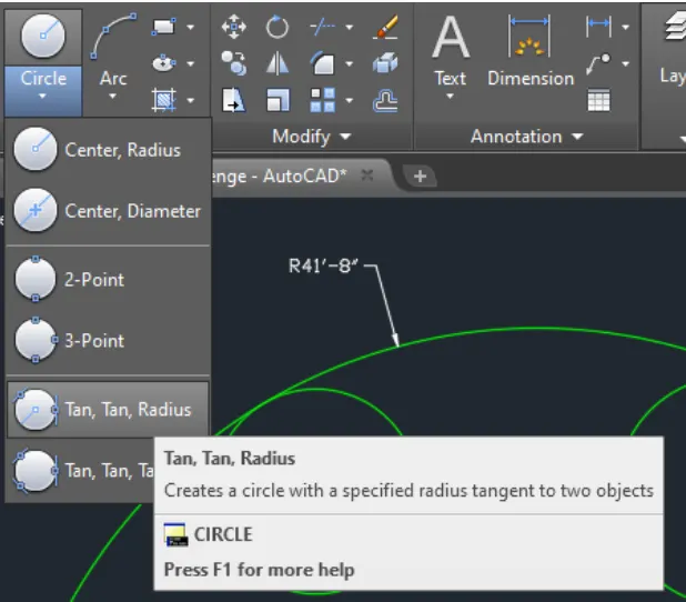
- Specify point on object for first tangent of circle: Upper part of left Circle
- Specify point on object forsecond tangent of circle: Upper part of right Circle
- Specify radius of circle:500
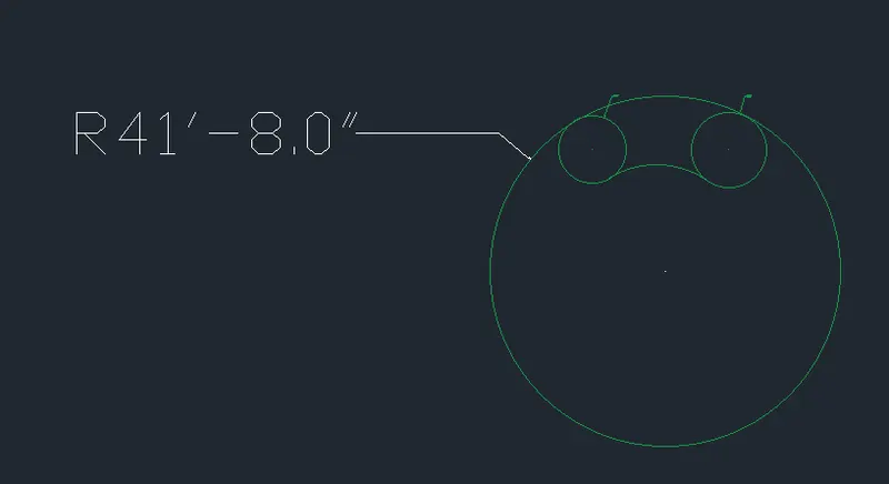
- Trim the excess circle outside. Select "Trim" tool
- Press enter to select all as cutting edges
- Select object to trim: Select the excess circle outside
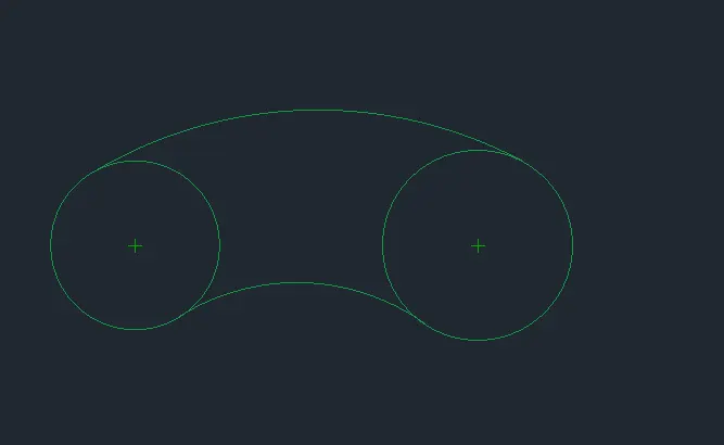
- Trim the excess circle outside.
- Select "Trim" tool
- Press enter to select all as cutting edges
- Select object to trim: Select the lines inside
FINAL PRODUCT:
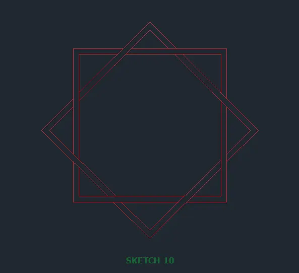
J. SKETCH 10:
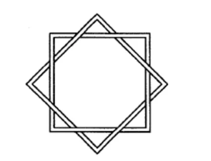
PROCEDURE:
- Make a square with equal sides. Select "Rectangle" tool
- Specify first corner point: Any Point
- Specify second corner point: X<Y(X and Y should be equal; let's say 5 units; 5,5)
- Add a point to specify the center of the rectangle. Select "Point" tool
- Specify a point: Press Shift+Right Click, a window will appear. Select "Mid Between two Points"
- Specify first point of mid: Midpoints of left side of rectangle
- Specify second point of mid: Midpoint of right side of rectangle
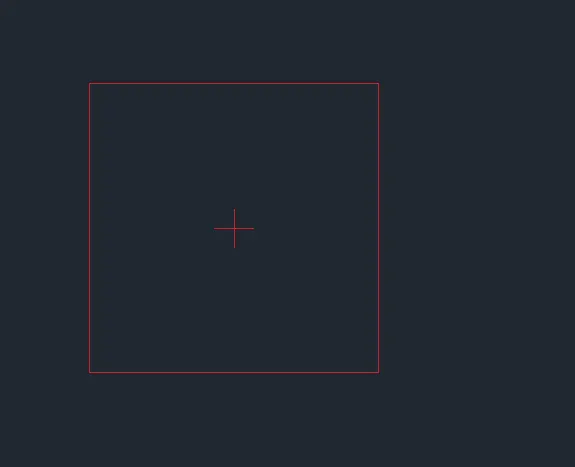
- Select the rectangle object
- Press Ctrl+Shift+C to proc copy tool
- Specify base point. The created point in the middle
- Press Ctrl+V ro proc paste tool
- Type "RO" to proc rotate command in the command prompt
- Specify rotation angle:45
- Specify insertion point: The point in the middle
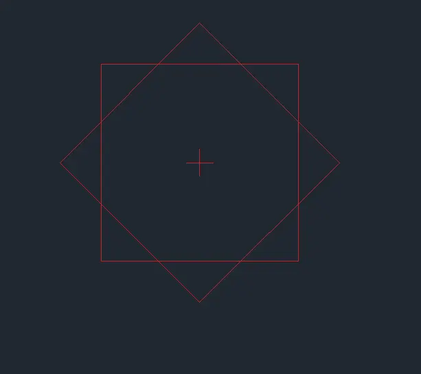
- To provide the thickness, use the offset tool. Select "Offset" tool
- Specify offset distance: Let's say 0.2
- Select object to offset: Select the diamond object
- Specify point on side to offset:Click any point in the middle of the rectangle
- Select object to offset: Select the diamond object
- Specify point on side to offset:Click any point in the middle of the diamond
- End
- trim the unnecessary lines: Select "Trim" tool
- Press enter to select all as cutting edges
- Selet object to trim:Select the unnecessary lines
FINAL PRODUCT:
K. SKETCH 11:
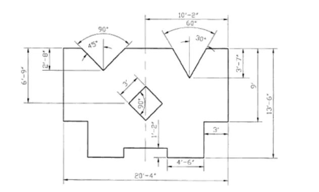
PROCEDURE:
Note: Engineering units used. 1feet(1') is equal to 12inches(12")
- Select "Rectangle" tool
- Specify first corner point: Any point
- Specify second corner poit:244,108
- Select "Rectangle" tool
- Specify first corner point: lower left corner of first rectangle
- Specify second corner point:54.-54
- Select newly created rectangle object. Select "Move" tool
- Specify base point: Any Point
- Specify second point:36,0
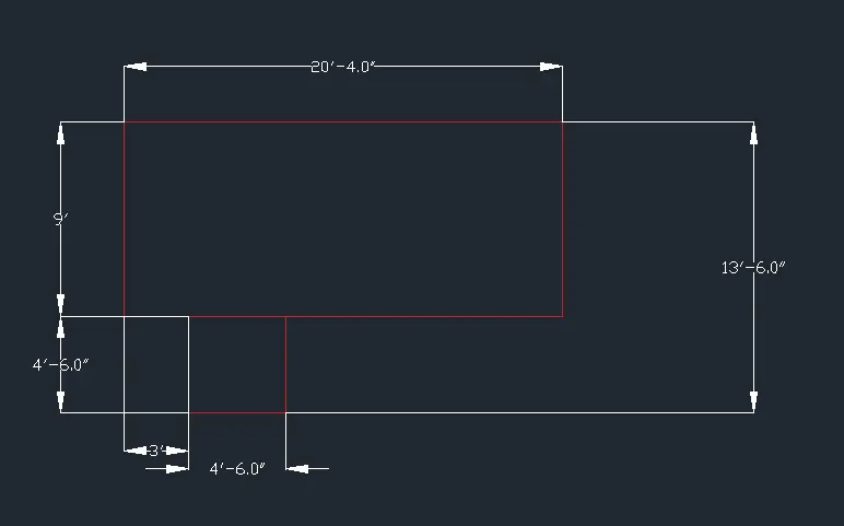
- Select the small rectangle object
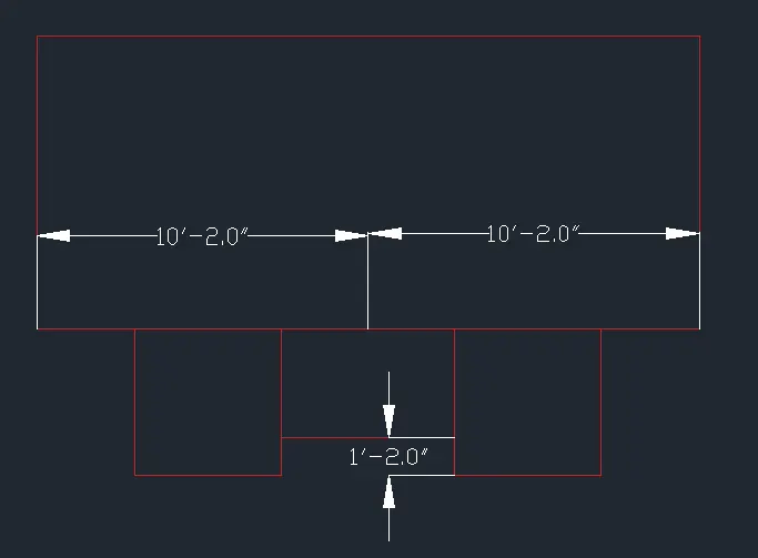
- select "Mirror" tool
- Specify first point of mirror line: Midpoint of upper line of big rectangle
- Specify second point of mirror line: Midpoint of lower line of big rectangle
- Select "Line" tool
- Connect the lower corners of the small rectangles
- Slect the line object
- Select "Move" tool
- Specify base point:Any point
- Specify second point:0,14
- Select "Line" tool
- Specify first point : upper left corner of big rectangle
- Specify second point : @L<45 (Assume length=50)
- Slect the line object
- Select "Mirror" tool
- Specify first point of mirror line: upper left corner of big rectangle
- Make sure Ortho mode is turned on. Specify second point of mirror line: Any point
- Erase object:No
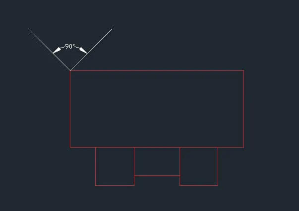
- Do the same on the right corner but use 60 degree angle instead of 45 degree
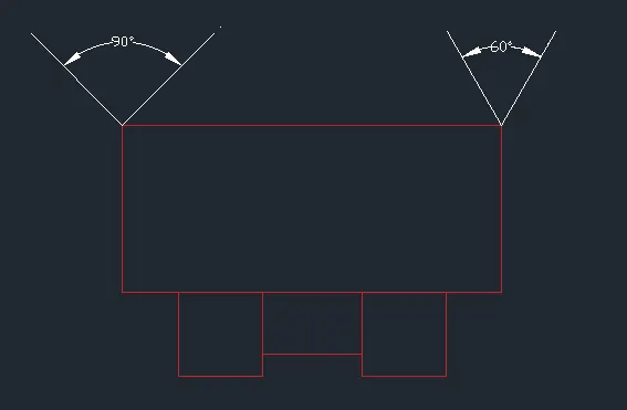
- Move the lines. Select the two line objects on the upper left side
- Select "Move" tool
- Specify base point : upper left corner of rectangle
- Specify second point:61,-32
- Select the two line objects on the upper riight side
- Select "Move" tool
- Specify base point: Upper right corner of rectangle
- Specify second point:-61,-43
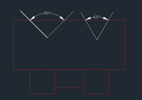
- Trim the excess lines. Select "Trim" tool
- Press enter to select all as cutting edges
- Select object to trim: Delete excess line
- Create a rectangle on the midpoint of the upper line of the big rectangle. Select "Rectangle" tool
- Specfy first corner point: Midpoint of upper line of big rectangle
- Specify second corner point:36,36
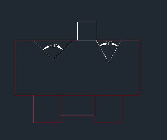
- move the rectangle to the middle. Select rectangle object
- Select "move" tool
- Specify base point:Any point
- Specify second point:-18,-18
- Rotate the rectangle 45 degrees to make a diamond. Select the rectangle object
- Select "Rotate" tool
- Specify base point:Midpoint of the upper line of the big rectangle
- Specify rotation angle:45
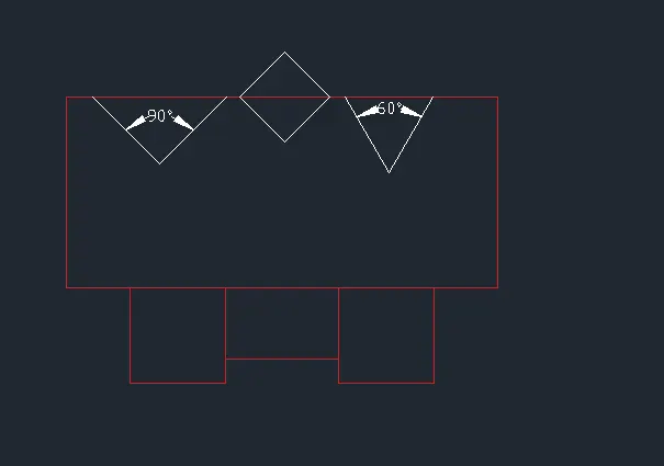
- Move the diamond down nd delete excess lines using the trim tool. Select the diamond object
- Select "move" tool
- Specify base point:Any point
- Specify second point:0,-81
- Select "Trim" tool
- Press to select all as cutting edges
- Select object to trim: trim unnecessary lines
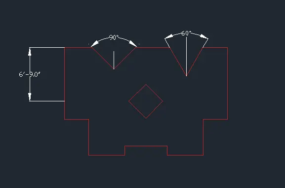
- To complete the sketch,copy, paste and rotate the diagonal line to form the center line. Select right line of the 90 degree diagonal lines
- press Ctrl+shift+C to proc copy tool
- Specify base point: The lower endpoint of the lines
- Press Ctrl+V to proc paste tool
- Type "RO" to proc rotate command in the command prompt
- Specify rotation angle:45
- Specify insertion point: The lower endpoint of the lines
- Do the same on the other side but use 30 degrees
- Press Ctrl+Shift+C to proc copy tool
- Specify base point: The lower endpoint of the ines
- Press Ctrl+V to proc paste tool
- Type "RO" to proc rotate command in the command prompt
- Specify rotation angle:30
- Specify insertion point: The lower endpoint of the lines
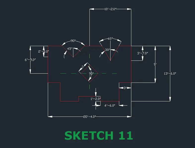
3.CONCLUSION:
To conclude the challenge, we can say that by the use of the AutoCAD software, various kinds of geometries can be drawn or sketched. There are lot of different tools and methods to create the drawing. By practicing all the tools in AutoCAD software, there can be no geometry that cannot be drawn. By combining the tools in AutoCAD, simplification of any geometrical shapesin the 2D dimension can be achieved. Weather it is a straight line, elipse, arc or any 2D geometrical shape, there can be multiple methods that can be used to draw these geometries.