Creating a Floor plan, Footing detail and Isometric view using AutoCad
1. Aim
The aim of this project is to create a deeper understanding in the use of the AUTOCAD software. In the project, the move and copy command are given emphasis in the creation of the sketches. A sketch provided and the procedures are given. the creation of isometric drawings are also provided in this project. The procedures given is one way to draw the sketch but other possibilities or methods can be done as well.
2. AutoCAD Tools
The following tools AutoCAD used in this challenge are as follows:
- Line/Polyline
- Rectangular Geometry
- Move command
- Copy Command
- Ortho and Snap Tools(Ortho and snap must be turned On)
General procedure for move and copy command
- Select object
- Select "MOVE" or "COPY" command
- Specify base point of object
- Specify second point by:
-Pointing to desired direction and typing the units of measurement.
-Specifying the location(@x,y)
-Clicking to any point
3. Sketch and Procedure
A). C.S of Load Bearing Wall Over Spread Footing
SKETCH:
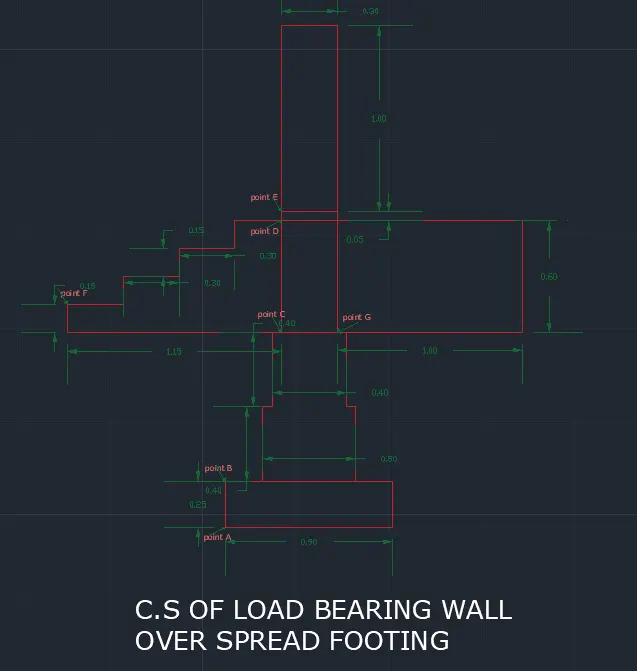
PROCEDURE:
- Select Rectangle tool
- Specifying any point:Point A (any point)
- Specifying any point of rectangle:@0.9, 0.25
- Select polyline tool
- Specifying first point:Point B
- Specifying next point: Point"RIGHT", 0.05
- Specifying next point: Point"UP", 0.40
- Specifying next point:Point"UP", 0.40
- Specifying next point: Point"RIGHT", 0.40
- Specifying next point: Point"DOWN", 0.40
- Specifying next point: Point"RIGHT", 0.05
- Specifying next point: Point"DOWN", 0.40
- Specifying last point: Point"LEFT", 0.50 OR CLOSE
- Select the poyline object and move 0.20 units to the right
- Select Rectangle tool
- Specifying first point:click Point C
- Specifying next point of rectangle:@0.3, 0.9
- Select Rectangle tool
- Specifying first point: click Point D
- Specifying next point of rectangle:@0.3, 0.05
- Select Rectangle tool
- Specifying first point: click Point E
- Specifying next point of rectangle:@0.3, 1.0
- Select Rectangle tool
- Specifying first point: click Point C
- Specifying next point of rectangle:@-1.15, -0.15
- Select Polyline tool
- Specifying first point: click Point F
- Specifying next point:Point"UP", 0.15
- Specifying next point: Point"RIGHT", 0.30
- Specifying next point:Point"UP", 0.15
- Specifying next point: Point"RIGHT", 0.30
- Specifying next point:Point"UP", 0.15
- Specifying next point: Point"RIGHT", 0.30 End
- Select Polyline tool object and move 0.30 units to the right
- Select Rectangle tool
- Specifying first point: click Point G
- Specifying next point of rectangle:@1.0, 0.60
B). C.S Isolated Footing
SKETCH:
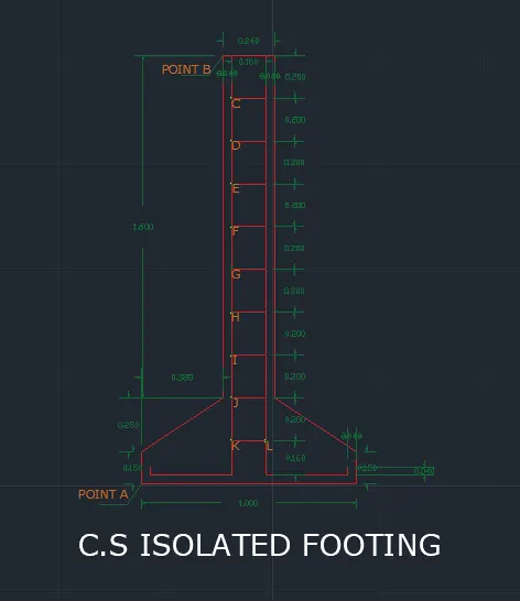
PROCEDURE:
- Select Polyline tool
- Specifying first point: click Point A(ANY POINT)
- Specifying next point:Point"UP", 0.15
- Specifying next point:@0.38, 0.25
- Specifying next point:Point"UP", 1.60
- Specifying next point: Point"RIGHT", 0.24
- Specifying next point:Point"DOWN", 1.0
- Specifying next point:@0.38, -0.25
- Specifying next point: Point"DOWN", 0.15
- Specifying last point: Point"Left", 1.0 or close
- Select Rectangle tool
- Specifying first point: click Point B
- Specifying next point of rectangle:@0.16, -0.20
- Select Rectangle and move 0.04 units to the right
- Select Rectangle again and select copy tool
- Specifying base point: Upper left corner of rectangle
- Specifying second point: click Point C
- Specifying second point: click Point D
- Specifying second point: click Point E
- Specifying second point: click Point F
- Specifying second point: click Point G
- Specifying second point: click Point H
- Specifying second point: click Point I
- Specifying second point: click Point J
- Select Polyline tool
- Specifying first point: click Point K
- Specifying next point:Point"DOWN", 0.16
- Specifying next point:Point"LEFT", 0.38
- Specifying next point:Point"UP", 0.04 End
- Select Polyline tool
- Specifying first point: click Point L
- Specifying next point:Point"DOWN", 0.16
- Specifying next point:Point"RIGHT", 0.38
- Specifying next point:Point"UP", 0.04 End
C). Line Diagram of Two Bedroom Building
SKETCH:
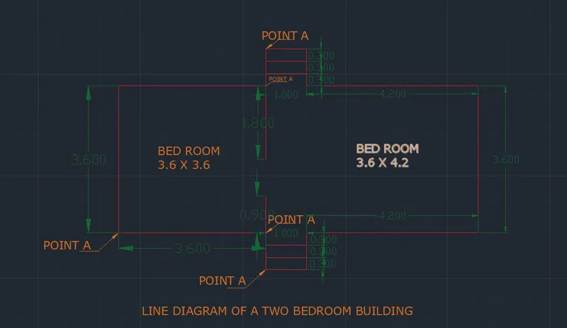
PROCEDURE:
- Select Polyline tool
- Specifying first point: click Point A (any point)
- Specifying next point:Point"UP", 3.6
- Specifying next point:Point"RIGHT", 3.6
- Specifying next point:Point"UP", 0.90
- Specifying next point:Point"RIGHT", 1.0
- Specifying next point:Point"UP", 0.90
- Specifying next point:Point"RIGHT", 4.2
- Specifying next point:Point"UP", 3.6
- Specifying next point:Point"RIGHT", 4.2
- Specifying next point:Point"UP", 0.90
- Specifying next point:Point"RIGHT", 1.0
- Specifying next point:Point"UP", 0.90
- Specifying last point:Point"LEFT", 3.6 or close
- Select Line tool
- Specifying first point: Point B
- Specifying next point:Point"RIGHT", 1.0 End
- Select line object:Move Up 0.30 units
- Select line object:Copy Up 0.30 units
- Select Line tool
- Specifying first point: Point C
- Specifying next point:Point"RIGHT", 1.0 End
- Select line object:Move Down 0.30 units
- Select line object:Copy Down 0.30 units
- Select Line tool
- Specifying first point: Point D
- Specifying next point:Point"DOWN", 1.8 End
- Select Line tool
- Specifying first point:Point E
- Specifying next point:Point "UP", 0.9 end
D). C.S. of Load Bearing Wall Showing Foundation details
SKETCH:
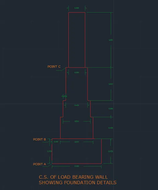
PROCEDURE:
- Select Rectangle tool
- Specifying any point:Point A (any point)
- Specifying any point of rectangle:@0.9, 0.25
- Select polyline tool
- Specifying first point:Point B
- Specifying next point: Point"RIGHT", 0.15
- Specifying next point: Point"UP", 0.40
- Specifying next point:Point"RIGHT", 0.05
- Specifying next point: Point"UP", 0.30
- Specifying next point: Point"RIGHT", 0.05
- Specifying next point: Point"UP", 0.60
- Specifying next point: Point"RIGHT", 0.40
- Specifying next point: Point"DOWN", 0.60
- Specifying next point: Point"RIGHT", 0.05
- Specifying next point: Point"DOWN", 0.30
- Specifying next point: Point"RIGHT", 0.05
- Specifying next point: Point"DOWN", 0.40
- Specifying last point: Point"LEFT", 0.60 or close
- Select the polyline object and move 0.15 units to the right
- Select rectangle tool
- Specify first point: Click point C
- Specify next point of rectangle:@0.3, 1.0
- Select the poyline object and move 0.05 units to the right
E). Isometric View of Steps
SKETCH:
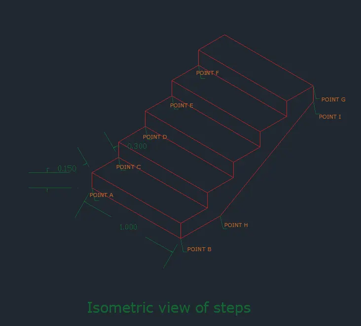
PROCEDURE:
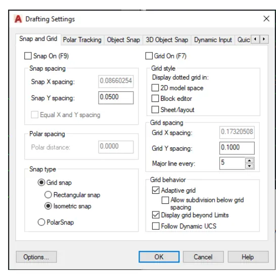
- Open Drafting Setting Window. Type "ds" in the command line
- Turn on the "Isometric Snap". Current plane is isoplane Right.
- Select Polyline tool
- Specifying first point:Point A (any point)
- Specifying next point: Point"UP", 0.15
- Specifying next point: Point"RIGHT", 0.30
- Specifying next point: Point"UP", 0.15
- Specifying next point: Point"RIGHT", 0.30
- Specifying next point: Point"UP", 0.15
- Specifying next point: Point"RIGHT", 0.30
- Specifying next point: Point"UP", 0.15
- Specifying next point: Point"RIGHT", 0.30
- Specifying next point: Point"UP", 0.15
- Specifying next point: Point"RIGHT", 0.30, end
- Press "F5" change Isoplane. Change Isoplane to "Isoplane Left"
- Select the polyline object and move 1.0 units to the right
- Select line tool
- Specifying first point:Point A
- Specifying next point: Point B, End
- Select line object and copy 0.15 units up
- Select the 2 line objects created
- Specifying base point: Point A
- Specifying next point: Point C
- Specifying next point: Point D
- Specifying next point: Point E
- Specifying next point: Point F
- Press "F5" change Isoplane. Change Isoplane to "Isoplane Right"
- Select line tool
- Specifying first point:Point B
- Specifying next point: Point "RIGHT", 0.30 End
- Select line tool
- Specifying first point:Point G
- Specifying next point: Point "DOWN", 0.15 End
- Select line tool
- Specifying first point:Point H
- Specifying next point: Point I, End
F). Isometric View of Gable Wall
SKETCH:
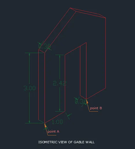
PROCEDURE:
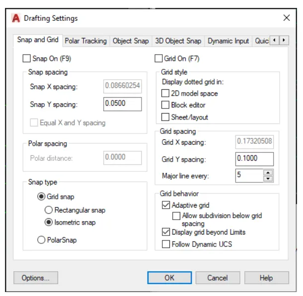
- Open Drafting Setting Window. Type "ds" in the command line
- Turn on the "Isometric Snap". Current plane is Isoplane Right.
- Select line tool
- Specifying first point:Point A (any point)
- Specifying next point: Point"UP", 3.0
- Specifying next point: Point"RIGHT", 1.5
- Specifying next point: Point"UP", 1.0
- Specifying next point: Point"DOWN", 1.0
- Specifying next point: Point"RIGHT", 1.5
- Specifying next point: Point"DOWN", 3.0
- Specifying next point: Point"LEFT", 1.0
- Specifying next point: Point"UP", 2.42
- Specifying next point: Point"LEFT", 1.0
- Specifying next point: Point"DOWN", 2.42
- Specifying next point: Point"LEFT", 1.0 or close
- The line should look like this:
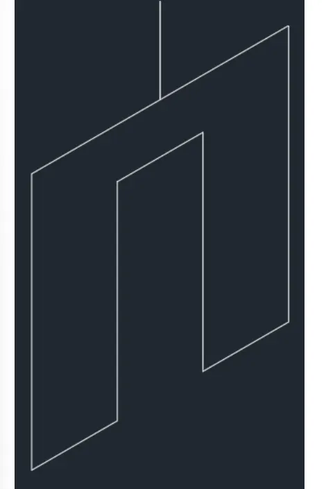
- Connect the lines above to form a triangular shape. Select line tool and connect the points as below.
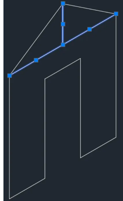
- Select the lines as specified above then delete it by using "Erase" tool or "Delete" button
- Press "F5" to change Isoplane. Change Isoplane to "Isoplane left"
- Select the line objects as specified below:
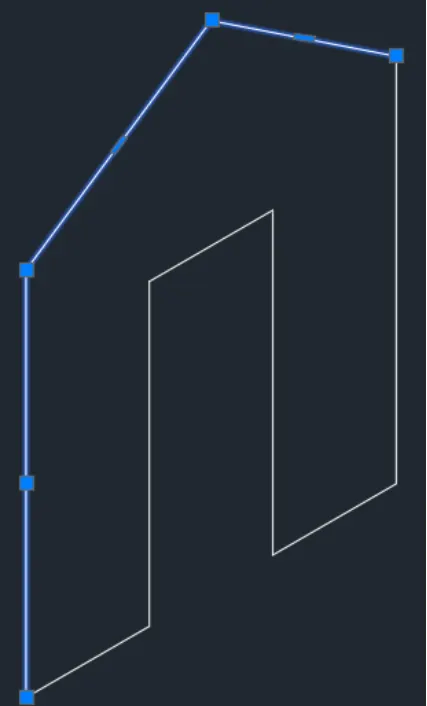
- Copy 0.30 units to the left
- Using the "line" tool, connect the edges as shown below:
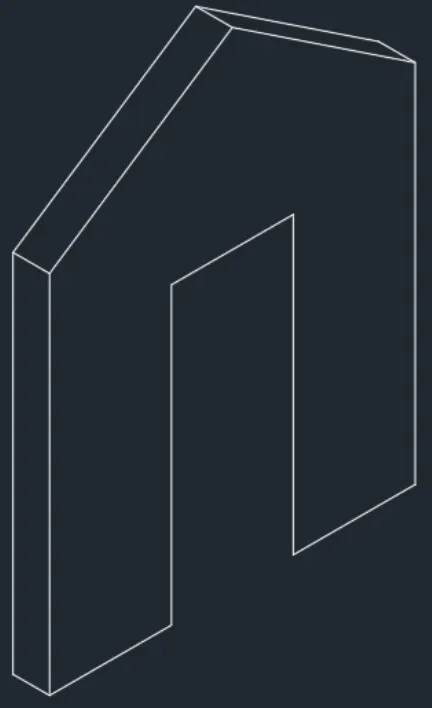
- Select Line tool
- Specify first point: Point B(as specified in the final sketch)
- Specify next point: Point "Left", 0.15
- Specify next point: Point "Up", 2.42 End
- Select the line object and click the "End Point"(blue box at the end of the line). This will allow you to stretch the line.
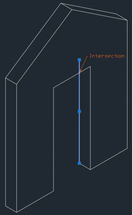
- Sketch the line to the intersection point to finish the sketch
4. Conclusion
The AutoCAD software can be used to sketch diffrent shapes to form into a larger picture. We can use the line tool, polyline tool, move tool, copy tool, rectangular tool, and many more. These commands are used in succession to complete any sketch given. The AutoCAD software has proved to be useful in the civil engineering industry. It is a great software to provide 2D plan illustrations or 3D sketchs.