MORPHING OPERATION ON A CAD MODEL USING ANSA
AIM: To perform a morphing operation on a CAD model by using ANSA.
OBJECTIVE:
- Geometry cleanup of a given sheet metal CAD model.
- To perform all the morphing techniques for CAD Model 1.
- To perform morphing on CAD Model 2 by increasing height of Dog houses and Ribs.
MORPHING: Morphing is used to change the design or shape of any component without numerical input.
A. CAD MODEL 1:
First, we have to Import the required CAD file in ANSA software by using GUI option. Once model is open, model looks like as shown in picture below.
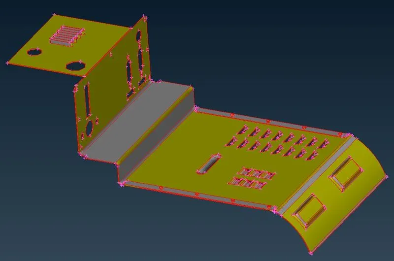
Figure 1: CAD Model1
PROCEDURE:
1. Geometry cleanup:
From model we can analyze that CONS are not connected to each other. To connect these single CONS we have to perform “TOPO” function which is available under Faces. Once topo is done, then we can see all CONS are connected and now CONS are in yellow color instead of red color CONS. Next step is to perform geometry cleanup, so geometry is free from errors.
In order to perform geometry cleanup, ANSA is having default selection parameters template. In template we will select all available options excepts sharp edges and unmeshed macros.
By selecting visible under execute on and then select execute to check the geometrical errors in the geometry. And we found geometry is free from errors.
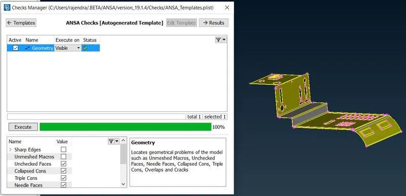
Figure 2: Geometry cleanup
2. Morphing the component with Morph Box
To change the design terminology. First of all, we have to create a morphing box for that particular object.
Steps to follow while doing Morphing. As we move to morph module, we can see Morphing Active at lower right corner of GUI as shown in picture below.
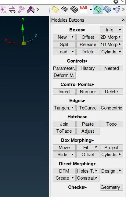 |
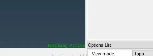 |
Figure 3: Morphing the component with Morph Box
2.1 To create a morphing box:
Once me move to morph module, first of all we have to create a new morphing box by following
Morph module---->New---->Ortho
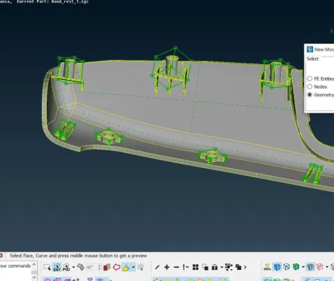
After these steps one window get popup with naming New Morph. By default, under “Select” option FE entities is selected. We are working on geometry not on FE model. So we will switch to Geometry. Under “Box Type” we will select Ortho as shown in picture below.
Then need to select the particular surfaces which need to capture for morphing.
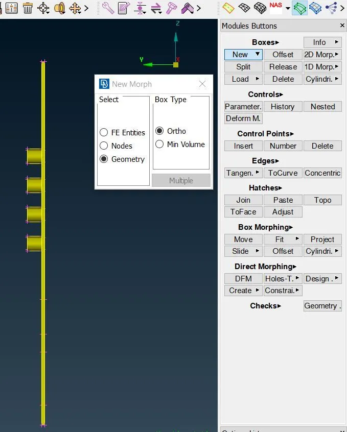
Figure 4: To create a morphing box
Once selection process is done. Then need to click middle mouse button in order to follow next step i.e. box generation.
Then a box will create around the selected surfaces as shown in picture below.
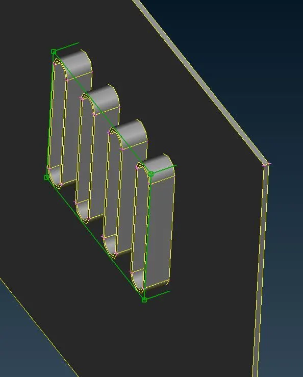
Figure 5: To create a morphing box
Similarly, we follow above mentioned steps for other areas also as shown in picture
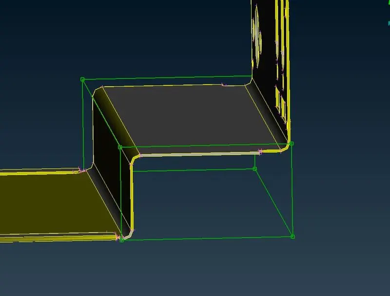
Figure 6: To create a morphing box
Again to apply morphing for desired areas, first we need to select all such areas by following above mentioned steps.
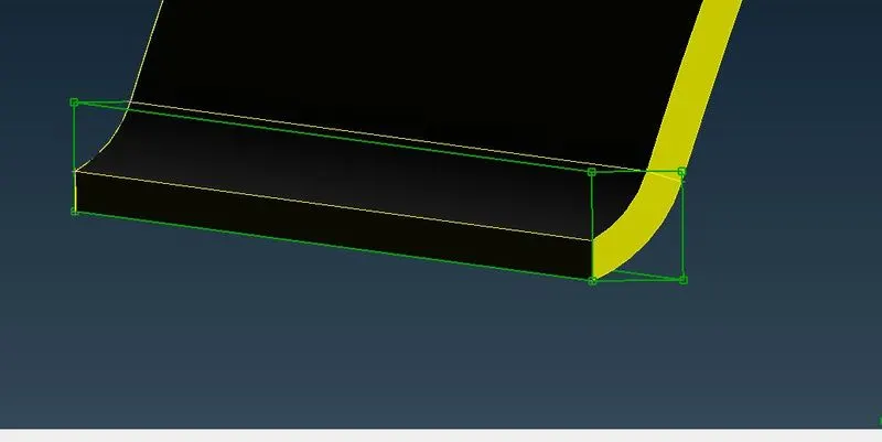
Figure 7: To create a morphing box
Once again we follow above steps to select remaining areas as shown in below picture
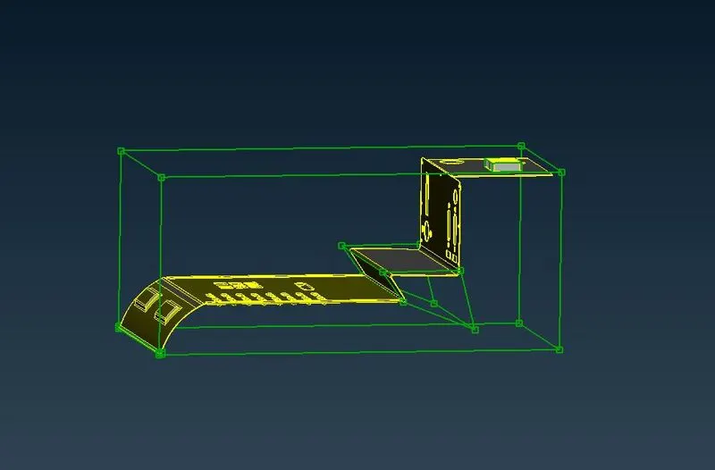
Figure 8: To create a morphing box
2.2 To Change the shape
To change the design or shape of any component, we need to follow
Morpho---->Box Morphing---->Move
On selection new window get pop-up with naming “Control Points Movement”. In this window we have two options i.e. entities and nodes. Coordinates can be moved according to local or global coordinates system. This window contains six different modes i.e. MvFree, Translate, Rotate, Scale, Transform, align.
Activates the “Entities” flag to select control point massively by picking relative morphing box, Hatch or Edge.
Activates the “Nodes” flag help to select individual control points.
Under Nodes we will select MvFree. By doing this three axis flag are activated by default. This means motion of any selected control point is free to allow in all three directions.
For this case we will deactivate X and Z fields. Which mean now control points are constrain in X and Z directions. So we can see the changes in object before or after the morphing operation as shown in picture below.
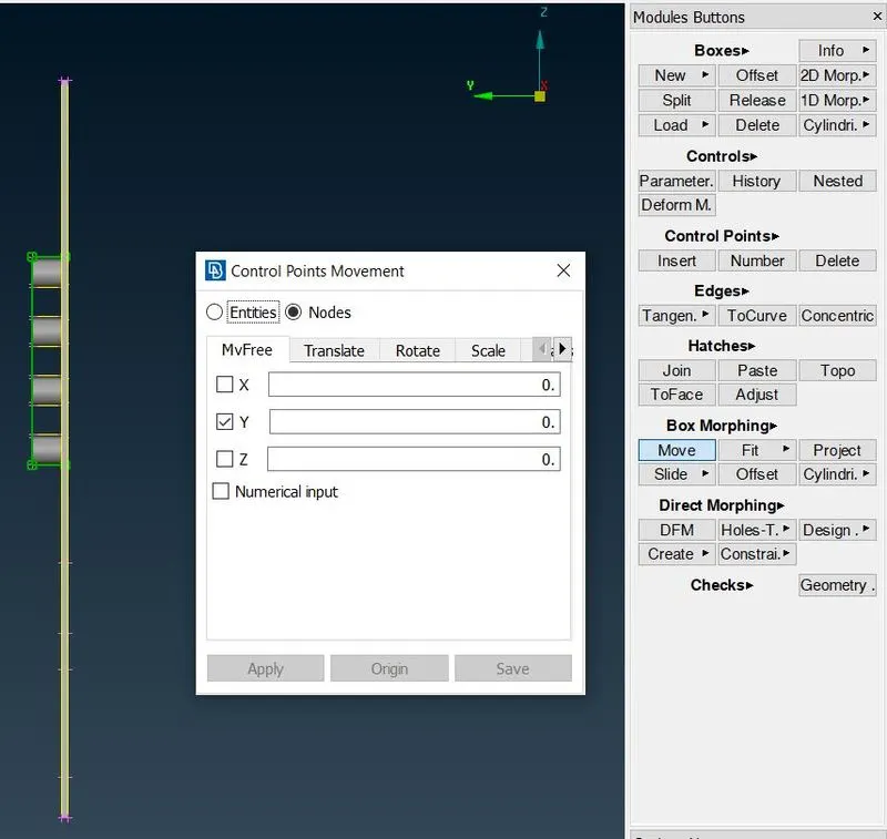 |
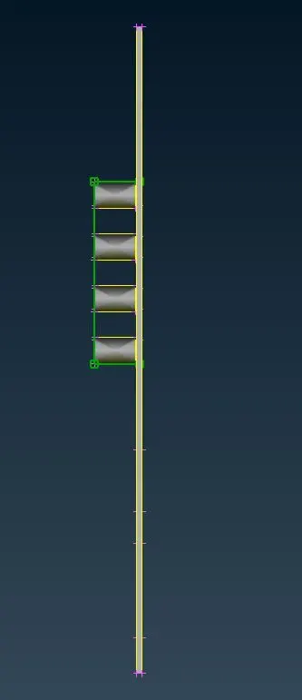 |
| BEFORE | AFTER |
Figure 9: To Change the shape
Similarly, above discussed steps will apply for other created box as shown below
|
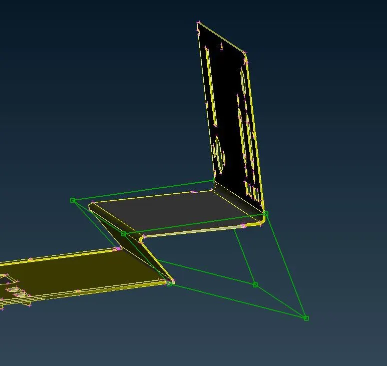 |
| BEFORE | AFTER |
Figure 10: To Change the shape
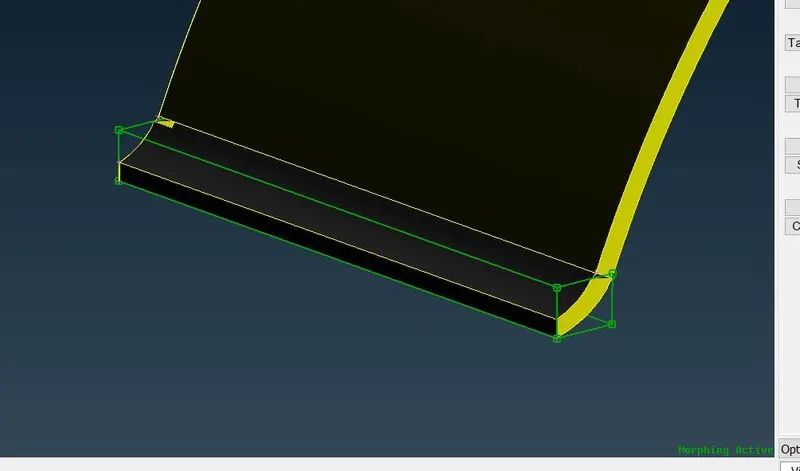
Similarly morphing is done for other areas. So we get new shape with little extension as shown below:
|
 |
| BEFORE | AFTER |
Figure 11: To Change the shape
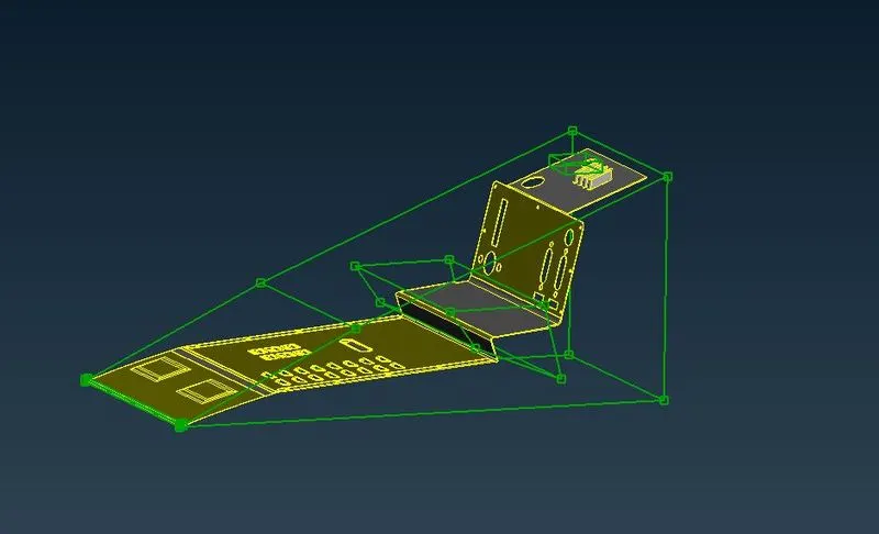
Once again to perform morphing on remaining area as shown in picture below.
|
 |
| BEFORE | AFTER |
Figure 12: To Change the shape
3. Morphing the component without Morph Box:
In order to change the design shape without any Morph Box. We will use Direct Morphing i.e. DFM. Steps to follow while using DFM is as shown
MORPH module---->Direct Morphing---->DFM
This function can perform massive morphing based on multiple type of selection i.e. Translate, Rotate, Scale, Transform, Offset, Align, Sweep / Guide.
After this operation new tab will open at left side. So we will work on Move Type i.e. Translate. Then it will ask for control entities i.e. FE entities and Geometry. Here, we are morphing the geometry, so we will select geometry. By following these steps also need to select surface or feature which need to translate as shown in picture below.
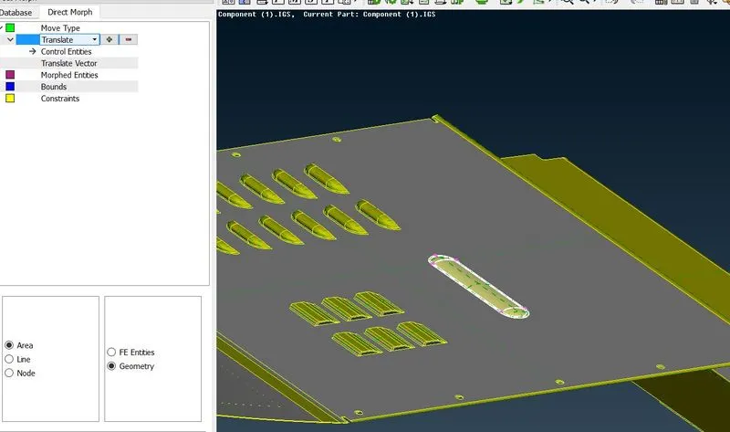
Figure 13: Morphing the component without Morph Box
After that in translate vector we have to select direction along which entity will move and also need to provide distance i.e. 75mm.
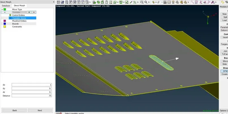
Figure 14: Morphing the component without Morph Box
Then next step is to define morphed entities. In Morphed entities we will select Geometry in options. And then need to select top and bottom surface around the stamp region as shown in picture below
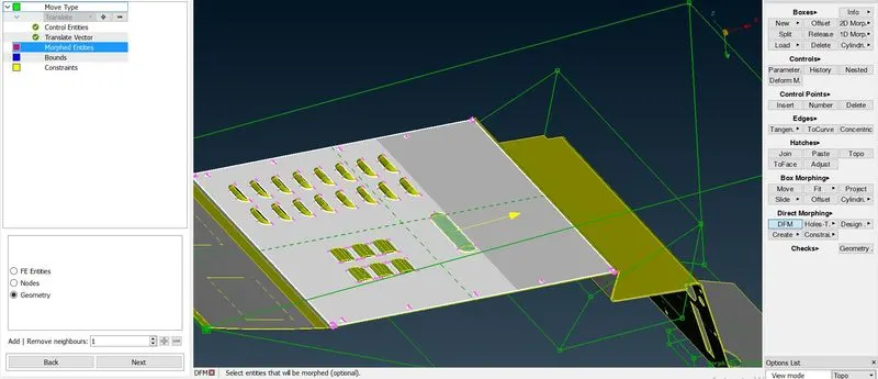
Figure 15: Morphing the component without Morph Box
Upon confirmation, selection moved to bound line. Which is optional so we can skip this level selection as shown in picture
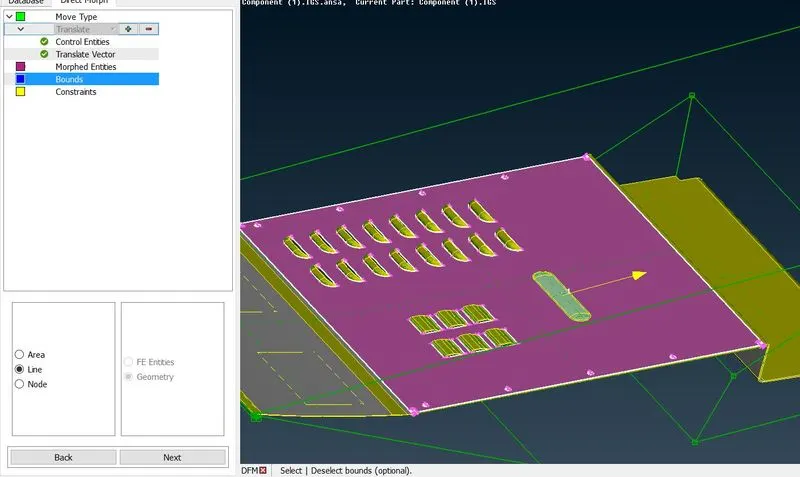
Figure 16: Morphing the component without Morph Box
Upon confirming and accepting the modification. we can see the changes in component before and after the translation as shown in picture below.
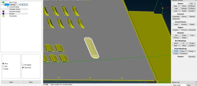 |
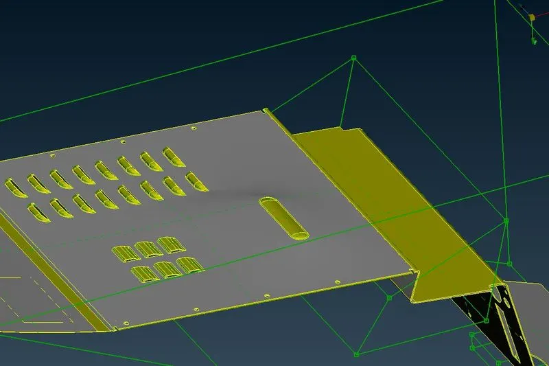 |
| BEFORE | AFTER |
Figure 17: Morphing the component without Morph Box
B. CAD MODEL 2:
Now we have to Import the required CAD file of model 2 in ANSA software by using GUI option. Once model is open, model looks like as shown in picture below.
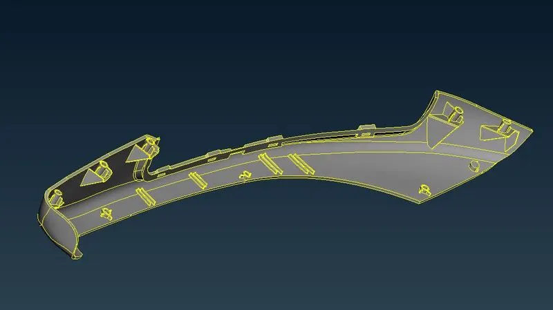
Figure 18: CAD MODEL 2
PROCEDURE:
1. Geometry cleanup:
After importing model 2, geometry cleanup will perform. Geometry cleanup help us to tell whether geometry is free from error. After performing geometry cleanup operation, we found geometry is free from error as shown in picture below.
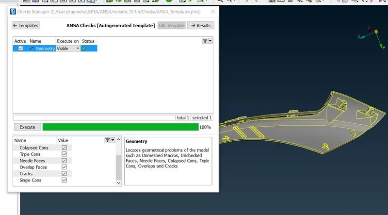
Figure 19: Geometry cleanup
2. Morphing the component with Morph Box
Now we will perform same operation as we discussed earlier for CAD model 1.
2.1 To create a Morph box:
Now we have to create a new morphing box by following
Morph module---->New---->Ortho
After these steps one window get popup, where we will select Geometry. Now, under “Box Type” we will select Min volume as shown in picture below. Min volume helps to define a morphing box oriented by means of minimum volume occupation.
Then we need to select the particular surfaces or features which need to capture for morphing.
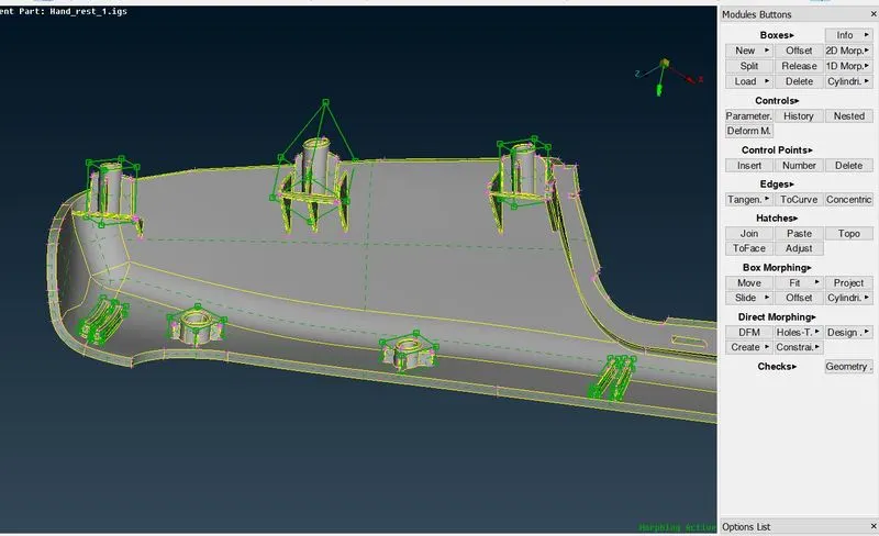
Figure 20: To create a Morph box
All the features are selected, for which we need to change the shape or design of the component.
2.2 To Change the shape
To change the design or shape of any component, we need to follow steps similar as we discussed earlier for CAD model 2
Morpho---->Box Morphing---->Move
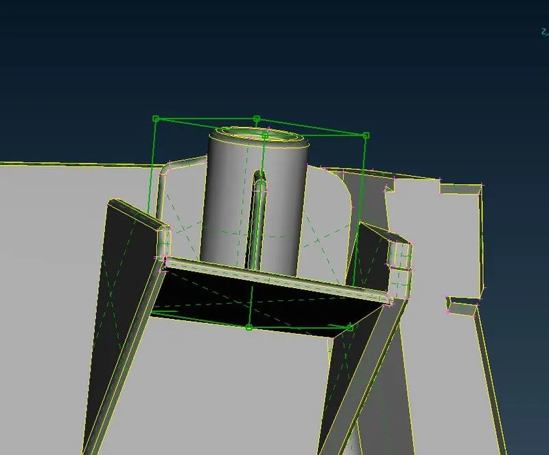
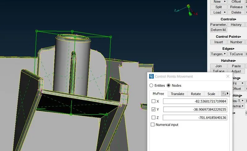
So we can see comparisons of particular regions before and after the changes as shown in picture below.
 |
 |
| BEFORE | AFTER |
Figure 21: To Change the shape
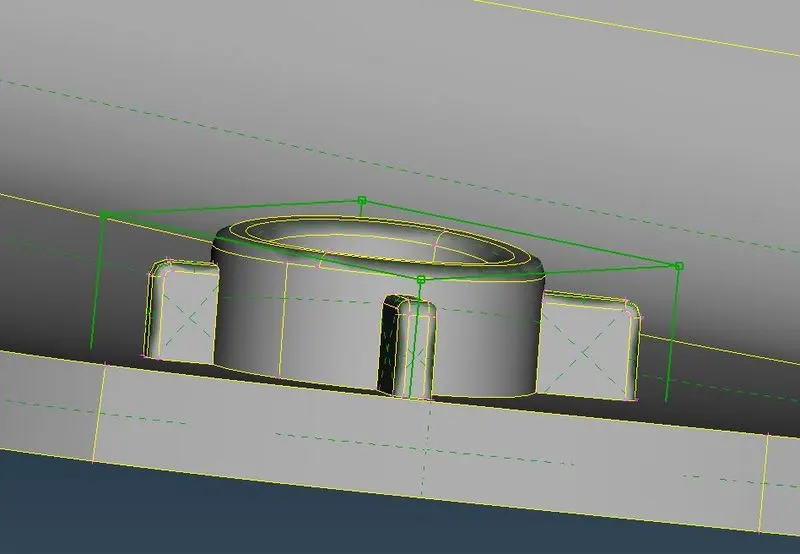
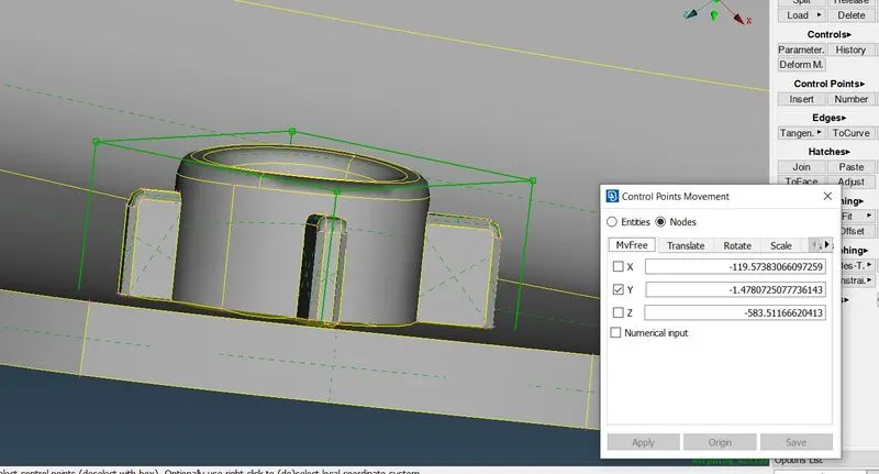
Similar operation has carried out on other features as shown in picture below.
 |
 |
| BEFORE | AFTER |
Figure 22: To Change the shape
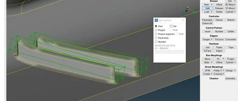
We have noticed after creating morph box, when we are trying to increase height of doghouse/rib region, then it is affecting the base of the component. In order to avoid this, we will use split function. Split function can be used by following
Morph module---->Boxes---->Split
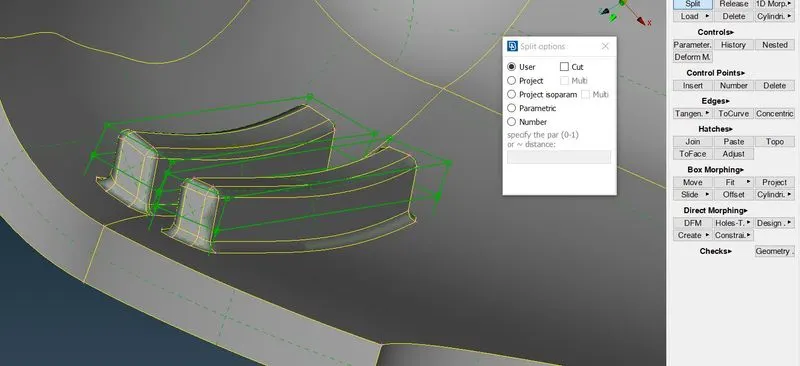
This split function split the boxes into smaller. And created box are connected to each other. After following above steps, split option window will get appear. We have to select user option under selection. Now, click the left mouse button at the position where split required. The created control points are common, as boxes are connected to each other.
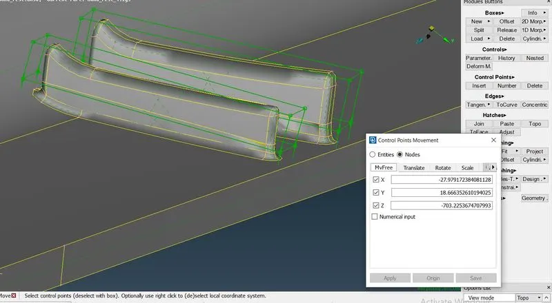
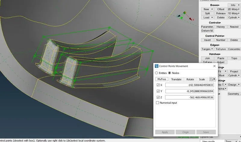
After using move control point option by following similar steps as described for CAD model 1. WE can see comparison before and after changes of design.
 |
BEFORE |
 |
AFTER |
Figure 23: To Change the shape
Similar operation is carried out for other regions as shown in picture below.
 |
BEFORE |
 |
AFTER |
Figure 24: To Change the shape
Applications of Morphing:
In automobile sector, most of industries are using morphing techniques to achieve design changes. This Techniques helps to reduce money as well as processing time.
We can take an example of Tata Tiago and Tata Tigor. Here, morphing technique is applied on Hatch-back version of Tata Tiago and get is convereted in to sedan version i.e. Tata Tigor.
Similar application we can take of hatch-back version of Honda BRIO and sedan version i.e. Honda Amaze.
In aerodynamic industries, morphing technique helps to improve aerodynamic efficiency.
LEARNING OUTCOMES:
- Learned the basics of morphing techniques.
- Learned how to create a morph box and how to move morph box by selecting nodes.
CONCLUSION:
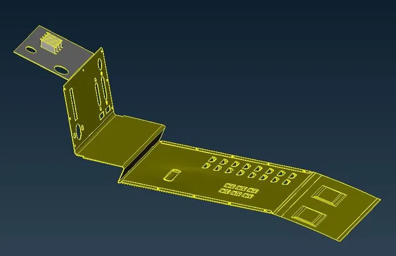
So, all the basics of morphing techniques are applied successfully for both models. So final design we got as per our requirement before and after the changes.
|
BEFORE |
 |
AFTER |
Figure 25: Comparison of CAD Model 1
 |
BEFORE |
 |
AFTER |
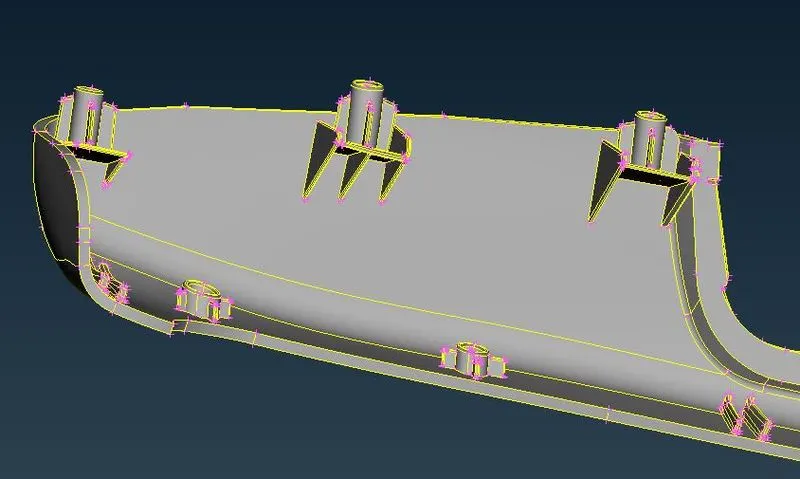
Figure 26: Comparison of CAD Model 2