Simulation of forward kinematics of a 2-R Robotic Arm
AIM : To write a program in MATLAB to simulate the forward kinematics of a 2-R robotic arm.
THEORY: A Robotic arm is a type of mechanical arm, usually programmable, with similar functions to a human arm; the arm may be the sum total of the mechanism or may be part of a more complex robot. The links of such a manipulator are connected by joints allowing either rotational motion (such as in an articulated robot) or translational (linear) displacement. The links of the manipulator can be considered to form a kinematic chain. The terminus of the kinematic chain of the manipulator is called the end effector and it is analogous to the human hand.
Types
Cartesian robot / Gantry robot: Used for pick and place work, application of sealant, assembly operations, handling machine tools and arc welding. It's a robot whose arm has three prismatic joints, whose axes are coincident with a Cartesian coordinator.
Cylindrical robot: Used for assembly operations, handling at machine tools, spot welding, and handling at diecasting machines. It's a robot whose axes form a cylindrical coordinate system.
Spherical robot / Polar robot Used for handling machine tools, spot welding, diecasting, fettling machines, gas welding and arc welding. It's a robot whose axes form a polar coordinate system.
SCARA robot: Used for pick and place work, application of sealant, assembly operations and handling machine tools. This robot features two parallel rotary joints to provide compliance in a plane.
Articulated robot: Used for assembly operations, diecasting, fettling machines, gas welding, arc welding and spray painting. It's a robot whose arm has at least three rotary joints.
Parallel robot: One use is a mobile platform handling cockpit flight simulators. It's a robot whose arms have concurrent prismatic or rotary joints.
Anthropomorphic robot: It is shaped in a way that resembles a human hand, i.e. with independent fingers and thumbs.
Forward kinematics of the Arm
Kinematics is the analysis of motion without considering its cause, such as forces and torques. So, for forward kinematics, the inputs will be the length of the links and the joint angles with the help of which, we can find the co-ordinates of the end effector.
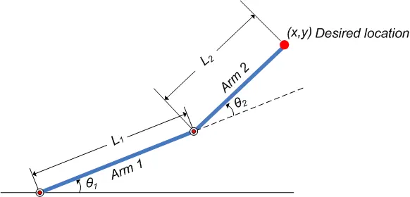
As we can see, the setup consists of a base, 2 links(arms) and 2 rotational joints. By varying the joint angles, the position of the end effector can be determined for each of its values.
Objective :
- To simulate the forward kinematics of a 2-R robotics arm.
- To create an animation file of the plot obtained (position of end effector).
Solution:
Language used: MATLAB
CODE#
%To simulate forward kinematics of a 2-R robotic arm

%inputs
 l1=1.5;      %length of link
 l2=1;

 theta1=linspace(0,90,10);   %joint angles
 theta2=linspace(0,90,10);
 ct=1;

 for i=1:length(theta1)
     T1=theta1(i);
     for j=1:length(theta2)
         T2=theta2(j);

         %co-ordinates

         x0=0;
         y0=0;

         x1=l1*cosd(T1);
         y1=l1*sind(T1);

         x2= x1 + l2*cosd(T2);
         y2= y1 + l2*sind(T2);

         %plotting
         plot([x0 x1],[y0 y1],[x1 x2],[y1 y2],'linewidth', 4);
         axis([-1 2 0 2.5]);
         title('Position of end effector');
         pause(0.03);
         M(ct)=getframe(gcf);
         ct= ct+1;
     end
 end

 movie(M)
 Videofile=VideoWriter('forward_kinematics.avi','uncompressed AVI');
 open(Videofile);
 writeVideo(Videofile,M);
 close(Videofile);
NOTE: 'for loop' is used bacause for each value of theta1,theta 2 will give 10 values. Hence,there will be 100 iterations and we'll obtain 100 different plots. Hence, an animation file is created.
OUTPUT: The animation file of the plot is obtained(click on the link below)
https://drive.google.com/drive/folders/10Y2Va9vKzkeWR7k7382wY-WfKf8p2HTN?usp=sharing
Conclusion: 1) The forward kinematics of the robotic arm is simulated.
2) The animation file of the plot is created.