Simulation of Forward kinematic motion of a 2-R and 3-R Robotic arm using Matlab.
Aim – To study and acknowledge the forward kinematic motion of a 2 linkage and 3 linkage robotic arm to utilize the space required for movement of a robotic arm for diversified applications.
Introduction – A robotic arm consists of rotary joint and manipulator for performing a particular operation. This Project describes the motion of a 2 linkage and 3 linkage robotic arm for the various operations, so to get different positions of the arm with varying angles (θ) and varying lengths (L). Accordingly, the length of robotic arm required for the particular operation can be validated and ultimately the range with which the robot can work will be calculated.
This project portrays following:
- Forward kinematics of a 2-R Robotic arm.
- Forward kinematics of a 3-R Robotic arm.
- Forward kinematics of a 2-R Robotic arm-
2-R Robotic arm consists of 2 linkages and 2 rotational joints. The input parameters are as follows.
L1 = Length of link 1;
L2 = length of link 2;
theta1 (Θ1) = angle made by link 1 with the ground;
theta2 (Θ2) = angle made by link 2 with the link 1.
Code to generate the forward kinematics of a 2-R Robotic arm –
%Forward kinematics of a 2R Robotic Arm.

%Inputs
L1 = 1
L2 = 0.5

theta1 = linspace(0,90,10);
theta2 = linspace(0,90,10);
ct = 1
%Program
for i = 1:length(theta1);
    Theta1 = theta1(i);
    for j = 1:length(theta2);
        Theta2 = theta2(j);

x0 = 0;
y0 = 0;

x1 = L1*cosd(Theta1);
y1 = L1*sind(Theta1);

x2 = x1 + L2*cosd(Theta2);
y2 = y1 + L2*sind(Theta2);

%Plot
plot([x0 x1],[y0 y1],[x1 x2],[y1 y2], 'Linewidth',2);
axis([-1 2 0 2]);
pause(0.03);
M(ct) = getframe(gcf);
ct = ct+1;
    end
end

movie(M)
videofile = VideoWriter('Forward_Kinematics_2R_Robotic_Arm.avi', 'uncompressed AVI')
open(videofile);
writeVideo(videofile,M);
close(videofile)
Explanation – L1 and L2 are the lengths of link 1 & 2 respectively. theta1 and theta2 are the angle made by linkages, on the basis of which positions of linkages (i.e. x1, y1 & x2, y2) are calculated.
Length of link1 and link2 are given as an input values. theta1 and theta2 are given by the command ‘linspace’ from 0 to 90 degrees with 10 instances.
In order to calculate the final positions of link 1 and link 2, it is assumed that link 1 starting co-ordinates as reference (i.e. x0 & y0 are 0)
Co-ordinates x1 and y1 are calculated by trigonometric relations. Similarly for link 2 x1 and y1 are taken as a reference and x2, y2 are calculated by adding the length of link 1 and by trigonometric relations of link 2.
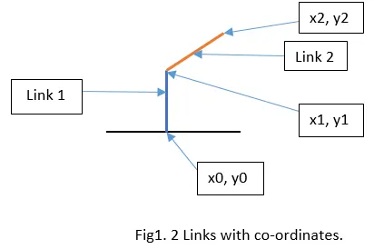
For loop is used to describe the theta with certain serial numbers. ct represents as a counter, which is incremented at the end to increment the position of linkages. M array is used to store all the individual frames by getframe command. Animation is created by movie command and it is written and stored inside the memory.
Forward Kinematics of 2R Robotic arm simulation –
2. Forward kinematics of a 3-R Robotic arm-
2-R Robotic arm consists of 2 linkages and 2 rotational joints. The input parameters are as follows.
L1 = Length of link 1;
L2 = length of link 2;
L3 = length of link 3;
theta1 (Θ1) = angle made by link 1 with the ground;
theta2 (Θ2) = angle made by link 2 with the link 1;
theta3 (θ3) = angle made by link 3 with the link 2.
Code to generate the forward kinematics of a 3-R Robotic arm –
% Forward Kinematics of 3R Robotic Arm

%Inputs
L1 = 1
L2 = 0.75
L3 = 0.5

theta1 = linspace(0,90,4);
theta2 = linspace(0,90,4);
theta3 = linspace(0,90,4);
ct = 1
%Program
for i = 1:length(theta1);
    Theta1 = theta1(i);
    for j = 1:length(theta2);
        Theta2 = theta2(j);
        for K = 1:length(theta3);
        Theta3 = theta3(K);


x0 = 0;
y0 = 0;

x1 = L1*cosd(Theta1);
y1 = L1*sind(Theta1);

x2 = x1 + L2*cosd(Theta2);
y2 = y1 + L2*sind(Theta2);

x3 = x2 + L3*cosd(Theta3);
y3 = y2 + L3*sind(Theta3);

%Plot
plot([x0 x1],[y0 y1],[x1 x2],[y1 y2],[x2 x3],[y2 y3], 'Linewidth',2);
axis([-1 2 0 2]);
pause(0.03);
M(ct) = getframe(gcf);
ct = ct+1;
    end
    end
end

movie(M)
videofile = VideoWriter('Forward_Kinematics_3R_Robotic_Arm.avi', 'uncompressed AVI')
open(videofile);
writeVideo(videofile,M);
close(videofile)
Explanation – theta1, theta2 and theta 3 are given from 0 to 90 degrees with 4 instances. To find the final positions of third link, one for loop should be added and theta3 should be given with the serial numbers. Final positions of link 2 is taken as a reference for link 3 and final co-ordinates are calculated by adding the length of link 2 and by trigonometric relations of link 3.
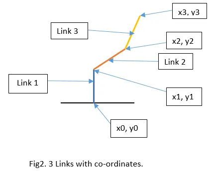
Forward Kinematics of 3R Robotic arm simulation –