Shock tube simulation project
SHOCK TUBE SIMULATION
Aim:
To setup the case of given Shock tube geometry and simulate with the Transient state flow in it by using Converge CFD.
Objectives:
- To setup the given Shock tube geometry case in Converge CFD.
- To simulate the Transient state flow of the Shock tube geometry case by CYGWIN.
- To simulate the Shock tube case physically using PARAVIEW.
- To create and analyze the plots of the simulation results by Converge CFD.
Case Setup:
- Open Converge CFD, click New Project and click and drag the given shock tube geometry.
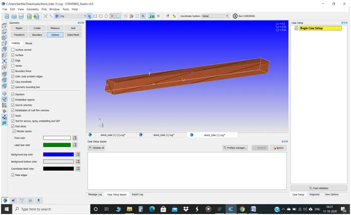
- Check the scale of the geometry with respect to Converge CFD which is in meters.
Shock tube geometry:
The Diaphragm inside the shock tube:
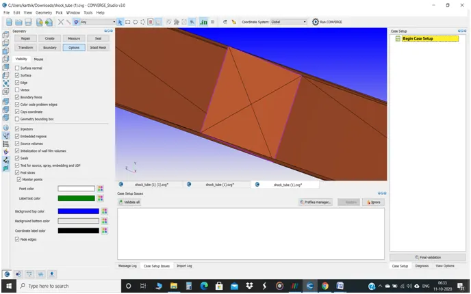
- It is important to check that the normals have been oriented in the direction of flow.
- Then, delete the Diaphragm plate in the geometry since there would be an intersection and also we could only give the conditions of the purpose of diaphragm (via events) rather than making it to burst.
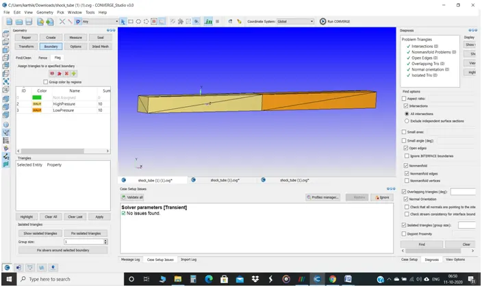
- The boundaries that have flagged in this case are only two, which are High Pressure and Low Pressure.
- In the Diagnosis tab, click Find to check whether the geometry is perfect to simulate as the picture:
- Then, click Begin Case setup
- The Application type is Time-based.
- The pre-defined mixture is Air.
- In Run parameters, Transient solver is chosen, Time-Based type and the simulation mode is Full Hydrodynamic.
- Make sure to uncheck the shared memory flag and uncheck the steady state monitor too.
- The simulation start time is 0 seconds, the end time is 0.003 seconds and the initial and minimum time step is 1e-09 seconds and maximum time step is 1 second.
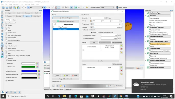
- Since the shock tube simulation consists of two different regions or two separate volume (one of high pressure and one of low pressure),so that, in regions and initialization, two regions named High_Pressure and Low_Pressure have been created.
- In High_Pressure region, the pressure of 600000Pa and the species N2 only of mass fraction of 1 has been given.
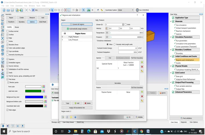
- In Low_Pressure region, atmospheric pressure of 101325Pa and the species O2 only and the mass fraction of 1 has been given.
- Then, in Boundary conditions, in the both HighPressure and LowPressure boundary, boundary type as Wall, the surface as slip wall and the temperature as Neumann boundary condition.
- The HighPressure boundary is assigned to High_Pressure region and the LowPressure is assigned to Low_Pressure region.
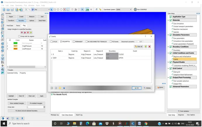
- Since, in the simulation, we cannot able to burst the diaphragm, only the purpose of the diaphragm can be given in terms of constraints via Events.
- To enable that, in Initial conditions and Events, click Events and Apply.
- In Events, enable Sequential mode, at 0 second, Region A as High_Pressure and Region B as Low_Pressure , the event is CLOSE and at 0.001 second with the same Region A & B, the event is OPEN.
- In Turbulence Modelling, the RANS RNG k-epsilon model has been used.
- The Base Grid size is 2e-03m.
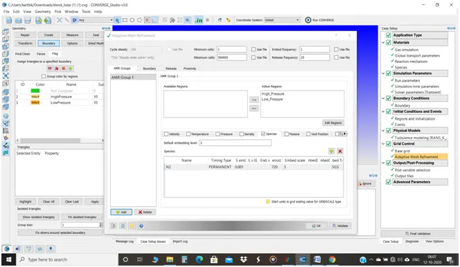
- In Grid control, the Adaptive Mesh Refinement (AMR) has been enabled.
- Adaptive Mesh Refinement (AMR) is the kind of a system which refines the mesh automatically where the accuracy of certain parameters is needed within the geometry while simulation.
- In AMR, Species type of AMR is chosen. The species is N2, embed level and scale as 3, embed type as SGS and Timing type as PERMANENT. The minimum cells is 0 and the maximum cells is 500000.
- Specify the Mass fraction of N2 and O2 in Post variable selection in order to get a finer simulation results in PARAVIEW and the flow or presence of N2 and O2.
- The time interval for writing 3D output data files is 0.0003 seconds and for text output & restart output files is 0.001 seconds.
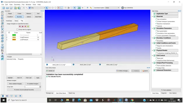
- The case setup is finished and it’s been validated successfully.
Time taken for the simulation in CYGWIN:
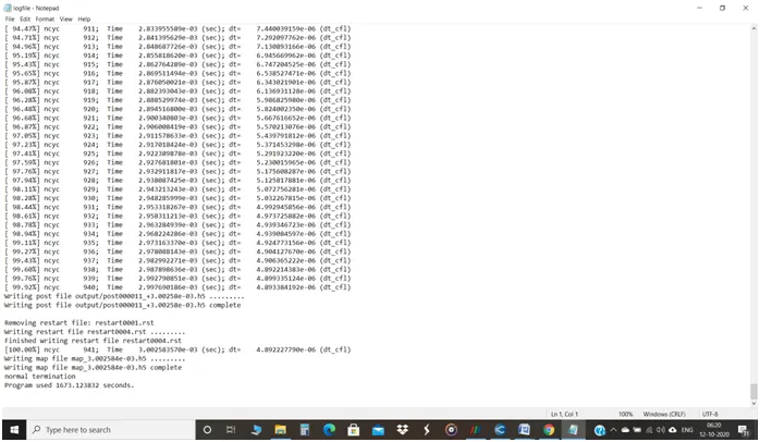
- The total time taken to complete the simulation in CYGWIN is 1673 seconds and since the case’s end time is 0.003 seconds, it takes about 941 cycles to complete 0.003 seconds.
Mesh Generation:
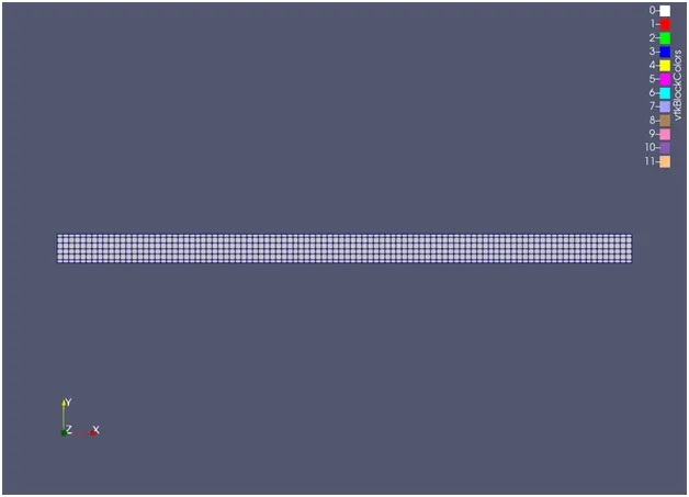
- Here the initial mesh size given which is 2e-03m without AMR is shown.
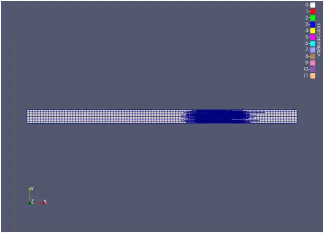
- Here the mesh with the working of AMR is shown.
The Mesh generation video with AMR: https://youtu.be/mJoNgQUMKgQ
Plots:
Pressure:
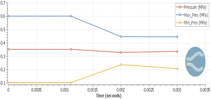
- Here, the pressure of both High Pressure region (Region 0) and Low Pressure region (Region 1) has seen in the common plot.
- The Region 0 pressure of 0.6MPa is Max. pressure and Region 1 pressure of 0.1 Mpa is Min. Pressure and the average pressure is 0.35MPa.
- From the plot, both the Region 0 and Region 1 are constant up to 0.001 second.
- At High Pressure Region (Region 0):
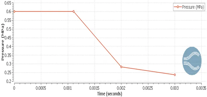
- After the time 0.001 seconds, since the diaphragm opens or bursts, the pressure will get decrease rapidly up to 0.28MPa due to the fluid flow from high pressure region to low pressure region.
- After 0.002 seconds, the pressure of region 0 decreases slowly due to the reverted flow of fluid and finally reaches 0.23MPa.
- At Low Pressure (Region 1):
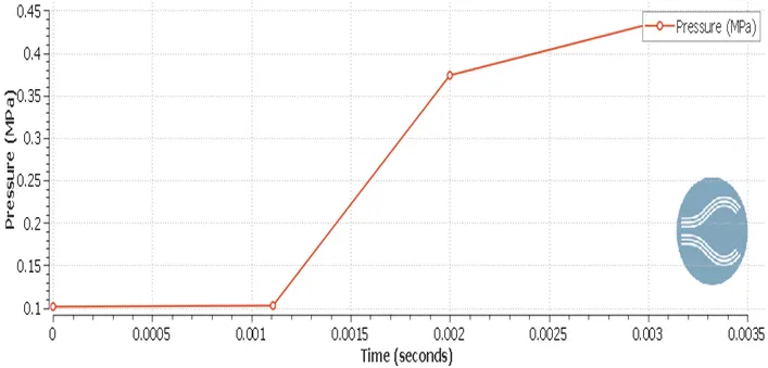
- Since the low pressure region is attacked by the high pressure N2 of 600000Pa, the pressure is high up to 0.37MPa after 0.001 seconds after that due to the reverted fluid flow, the pressure is slowly increasing and finally reaches 0.43MPa.
Temperature:
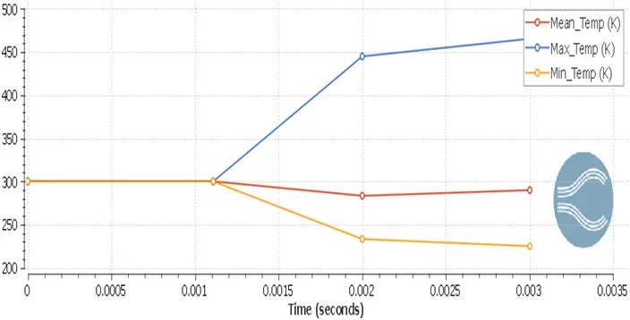
- In the common plots, both the given region’s temperature 300K is maintained up to 0.001 second.
- At High Pressure Region (Region 0):
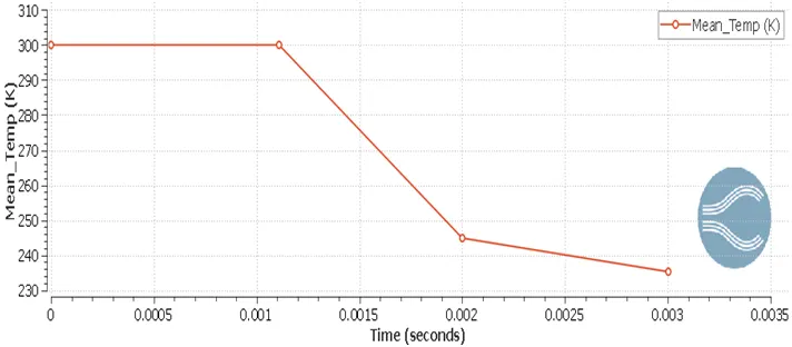
- Since the diaphragm blasts, after 0.001 second, the temperature is rapidly decreasing up to 245K due to the decrease in pressure as the fluid flows towards the Low Pressure region and due to the flow disturbance and slight increase in temperature, it decreases gradually and reaches 235K.
- At Low Pressure region (Region 1):
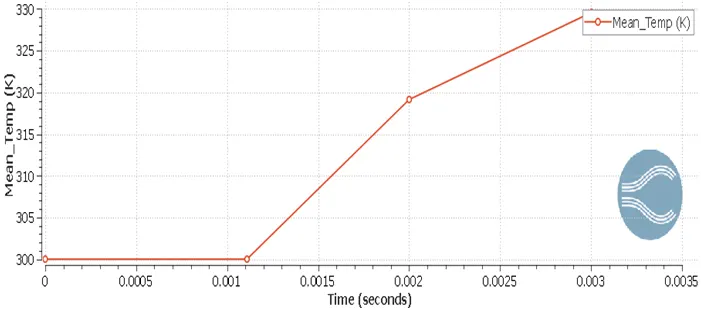
- Here, after 0.001 second, due to the high pressure fluid flow in the region 1, the temperature is rapidly increasing to 319K since the pressure is directly proportional to the temperature(P = kT).
- Eventually, it slows the fluid due to slight decrease in temperature in this region, it increases gradually and reaches to 329K.
Cell Counts:
- Total cell counts:
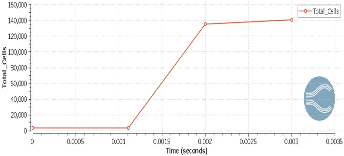
- Since we use AMR, it can be seen that after 0.001 second, the cell count has been increased from 3200 cells to 140000 cells in order to get the accuracy of the particular parameter.
- Cell count plots by Regions:
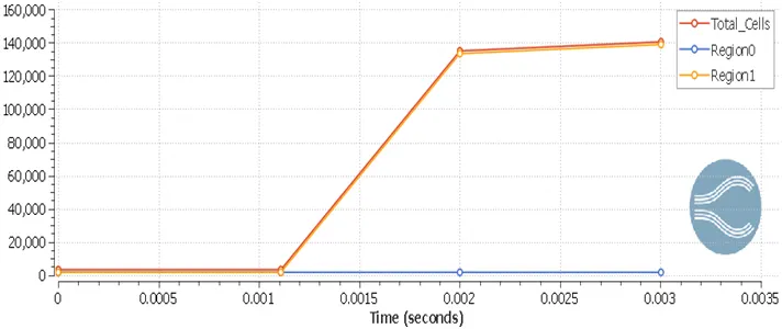
- From the above graph, it seems that the mesh refinement by AMR in the region 0 has not taken place, only in the region 1 has been refined by AMR of about 137000 cells since there might not be any need of accuracy with the base mesh.
Flow over a Shock Tube:
- Shock Tube is a tube structured in which the high pressure gas and low pressure gas have been separated by a diaphragm.
- When the diaphragm suddenly bursts, the high pressure gas rushes through the low pressure gas region and in turn creates the shock waves which leads to increase in pressure and temperature.
- It can be applied for solving or analyzing in the subject of chemical kinetics to calculate the ignition delay, for aerodynamic tests,etc.,
Pressure:
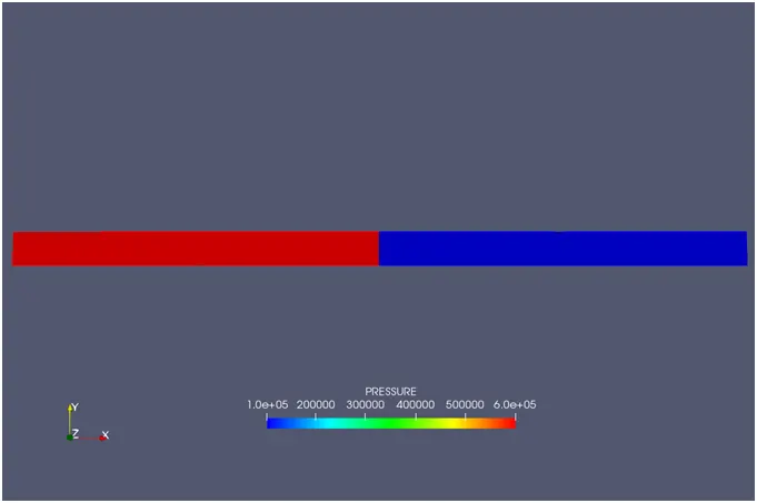
- Initially, the pressure at region 0 is high since it is of 600000Pa and the region 1 is low pressure of atmospheric pressure.
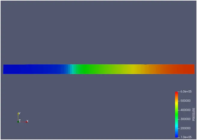
- Once the diaphragm bursts, the pressure will be high in the region 1 whereas low in the region 0 since the high pressure of N2 rushes into the low pressure region of O2, as per Bernoulli’s principle.
- So, due to the high pressure waves in the region 1, it has high pressure.
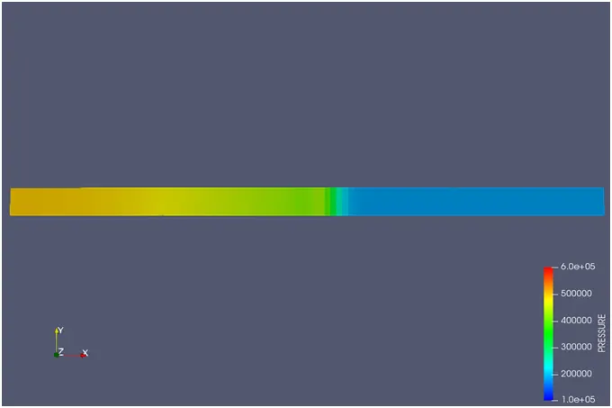
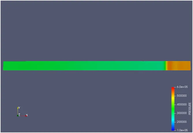
- After sometime, those high pressure waves or shock waves will reflect back and causes high pressure in the region 0 than region 1.
- Eventually, these shock waves will reflect back to the region 1 which causes high pressure at the end of the region 1.
Temperature:
- Initially the temperature is maintained constant at 300K in both region 0 and region 1.
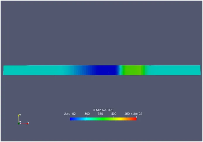
- When the diaphragm bursts, since the high pressure N2 enters to region 1 of O2, the temperature starts to increase in region 1.
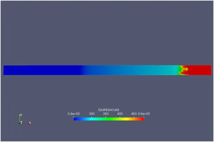
- Then the temperature will be high at the end of the region 1 due to the high pressure waves or shock waves.
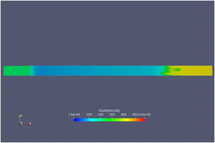
- After that due to the high pressure waves, the fluid flow will revert to the region 0. So that, the temperature will be increasing around 350K in the region 0.
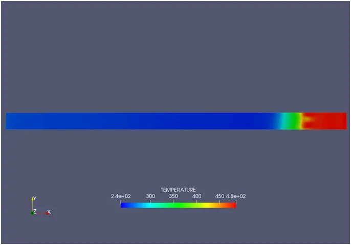
- Finally, the high pressure waves or the fluid will flow back to region 1 from region 0 and then results in high temperature around 480K in region 1.
Mass Fraction N2:
- Initially, in the case region 0 has high N2 and when diaphragm blasts, the huge pressure of N2 rushes to region 1 where the O2 is present at atmospheric pressure and creates high pressure waves in region 1.
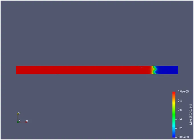
- After sometime, these high pressure waves or shock waves will reflect due to the pressure of oxygen and also the wall. Then the flow of nitrogen will get reverted.
- This results in some separated pressure waves.

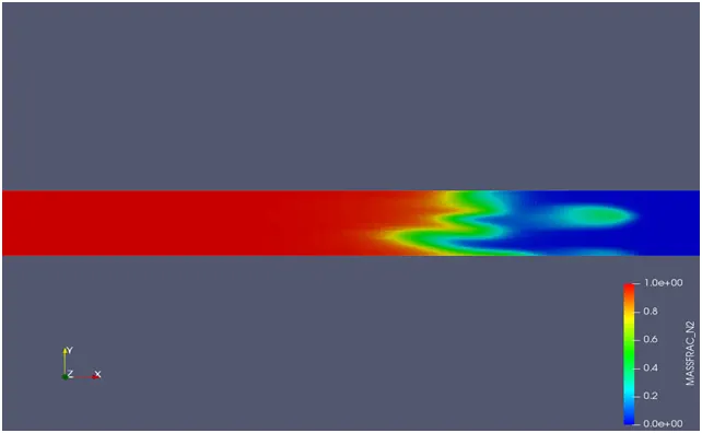
- After that, the flow will get back to the region 1 with the high pressure and the oxygen flow will get results some vortices.
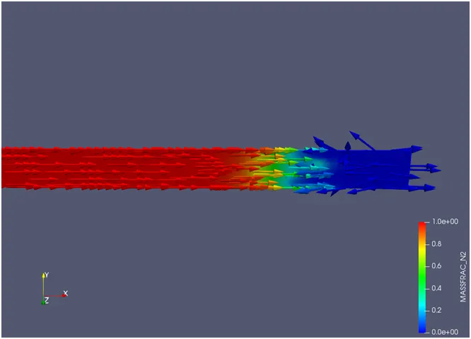
Conclusion:
- The simulation of the shock tube experiment has been done and the process of mesh refinement by AMR can be seen seperately.
- The presence of N2 (high pressure) and the pressure waves created by it, is clearly visible due to the AMR when it is reacting with the oxygen (low pressure).
- The variation of temperature and pressure is with respect to the flow of N2 or it's pressure waves.
- The Event option has been enabled only for as a replacement of diahragm since we cannot blast it in the simulation or cannot give such conditions in Converge CFD.
Links for the animation of Shock Tube simulation:
Pressure animation: https://youtu.be/5VMBndyA69E
Temperature animation: https://youtu.be/FwsWQ-9yzJI
Velocity animation: https://youtu.be/2XZCZnTFhwk
Reference: shocktube: https://en.wikipedia.org/wiki/Shock_tube#:~:text=The%20shock%20tube%20is%20an,usually%20on%20a%20smaller%20scale.