Project : Steady state simulation of flow over a throttle body
Steady state simulation of Flow over a throttle body
Aim:
To setup the given throttle body geometry and simulate the steady state flow over it by using Converge CFD.
Objectives:
- To setup the given Throttle body geometry case in Converge CFD.
- To simulate the steady-state flow of the Throttle body case by CYGWIN.
- To simulate the Throttle body case physically using PARAVIEW.
- To create and analyze the plots of the simulation results by Converge CFD.
Setting up the case in Converge CFD:
- Open Converge CFD and click New Project.
- Click and drag the given Throttle body geometry case.
- Check the scale of the geometry with respect to Converge CFD which is in meters. If it is in mm scale it to m.
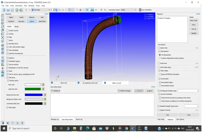
The entire throttle body geometry:
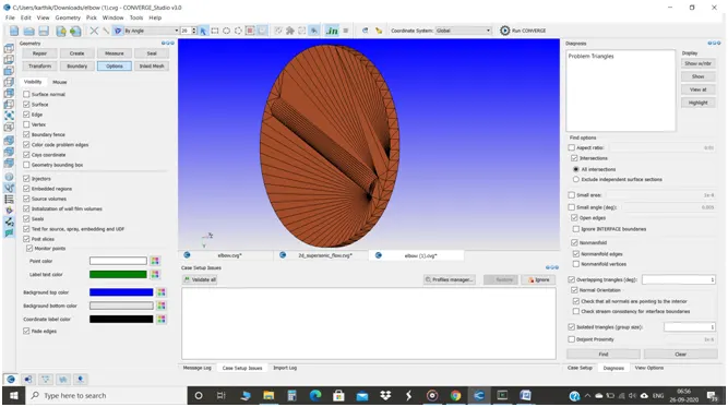
The throttle lever inside the geometry:
- The thickness of the geometry has been deleted since it is a normal steady state simulation of a normal air flow and not a conjugate heat transfer simulation.
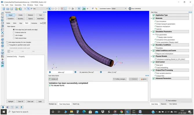
- The inlet and outlet of the pipe has been patched by Repair-->Patch-->Click Free edge loop-->Select the edge to be patched-->Ok.
- In the Diagnosis tab, click Find to check whether the geometry is perfect to simulate as the pic:
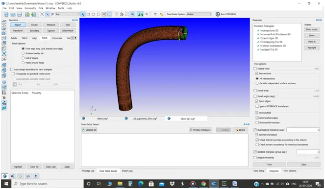
- The Boundaries that have flagged are Inlet, Outlet, Elbow wall and throttle.
- The Application type is Time-based.
- The pre-defined mixture is Air.
- In Run parameters, Steady-state solver is chosen and the simulation mode is Full Hydrodynamic.
- Make sure to uncheck the shared memory flag and check the steady state monitor and add the variable that has to be monitored and specify the target type and the target.
- In Boundary conditions, the boundary type of the Inlet as Inflow, Outlet as outflow, Throttle and Elbow as Wall
- At inlet, the pressure boundary condition is the specified value of 150000 Pa, the velocity as Neumann boundary condition and the Temperature as the specified value of 300K and the species as N2 of 0.77 and O2 of 0.23.
- At outlet, the pressure and temperature boundary condition as specified value of about 100000Pa and 300K and the species are N2 of 77 and O2 of 0.23.
- Both the throttle and the elbow boundary type as Wall with No-slip boundary condition and the Temperature is Neumann boundary condition.
- The Region0 has been created by Regions and Initialization with the atmospheric pressure of 101325Pa and temperature as 300K and it’s been assigned to all the boundaries.
- In Simulation time parameters, the start time is 0 , the end time is 16000 cyc. and the initial and minimum time step is 1e-9 sec. and the maximum time step is 3 sec.
- In Turbulence Modelling, the RANS RNG k-epsilon model has been used.
- The base grid of 2e-03m and with the default base grid, the fixed embedding type has also been enabled since the gap between the throttle plate and the throttle body wall is small or in order to get possible finer results around the throttle, since the variables like pressure and velocity will be varying
- In fixed embedding, Click Add and Entity type as Boundary and Boundary ID as throttle in Permanent mode with a scale of 3 and embed layers of 2.
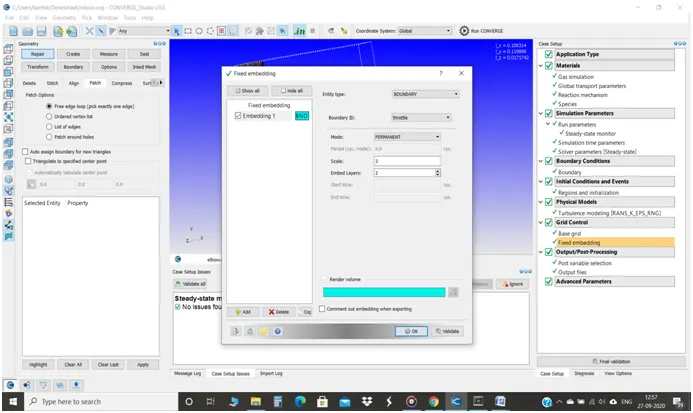
- It is also important to note that neither the base mesh size should be smaller nor the embedded mesh size should be larger or Vice versa.
- Specify the Mass fraction of N2 and O2 in Post variable selection in order to get a finer simulation results in PARAVIEW and the flow or presence of N2 and O2.
- Finally, the case setup is done.
Simulation by CYGWIN:
- Once the case setup is ready, the input files has been exported to the particular location and the copy and paste the mpiexec.exe file in that location.
- Then, the input files have been simulated in CYGWIN and we can see the total time taken for the simulation.
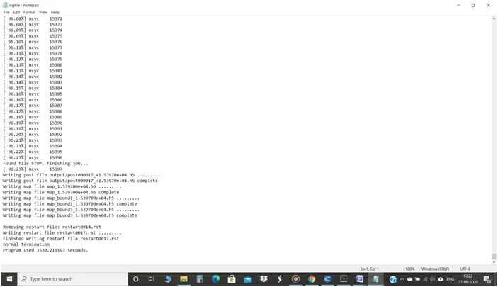
- The total time taken for the simulation is 3530 seconds.
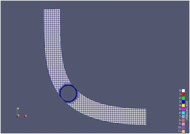
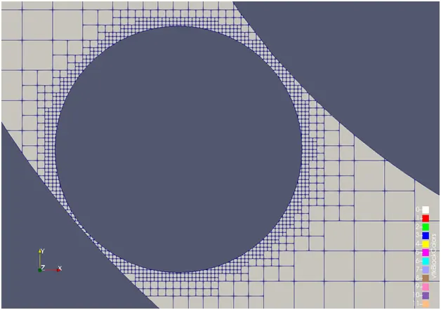
Surface Mesh of Throttle body:
- The Base grid size is 2e-03m and the Fixed embedding's scale is 3 and the embed layers is 2 and the boundary is Throttle.
Plots:
Velocity:
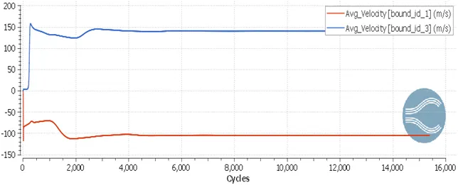
- Initially, the velocity reaches its higher value of about 120m/s and then due to the Throttle plate, the velocity drops down to the 80m/s.
- After that, it slowly reaches it’s possible higher value to 113m/s nearer to 2000 cycles.
- At outlet, in few cycles, due to throttle plate, the velocity very small as the cycles passing on the velocity seems to be higher and reaches its maximum point up to 154m/s.
- After that, at both inlet and outlet, it converges nearer to 6000 cycles.
Pressure:
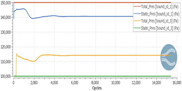
- At inlet, static pressure decreases in high rate up to 140000Pa due to the increase in dynamic pressure with the constant total pressure 150000Pa (Total pressure = static pressure + dynamic pressure).
- Then the static pressure is increasing up to 145000Pa and it again reaches 140000Pa due to the throttle plate which affects the dynamic pressure.
- At the outlet, the static pressure will be 100000 Pa and the total pressure value is increasing to 115000Pa and fluctuates, finally attains 114000Pa with respect to cycles due to increase in dynamic pressure.
Mass flow rate:
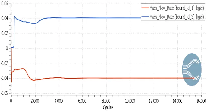
- Mass flow rate is defined as the mass of a substance which passes per unit time.
- The structure of the plots of mass flow rate seems to be as same as the structure of velocity plots.
- Initially, at inlet, the mass flow rate is 0.035kg/s and at outlet, after very few cycles it reaches the value of 0.04kg/s .
- After sometime, due to the throttle plate, the fluctuations happened and reached the lower value at inlet 0.042kg/s and at outlet 0.032kg/s.
- Eventually, the mass flow rate converges at 6000 cycles with a value of 0.04kg/s.
Total Cell count:
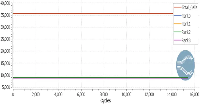
- From this plot, the total cell counts has been shown and used is 35500 cells. It also to be noted that we have been used 4 processors from rank 0, rank 1, rank 2 and rank 3.
Physical simulation by PARAVIEW:
Velocity of a throttle body:
At Elbow wall:
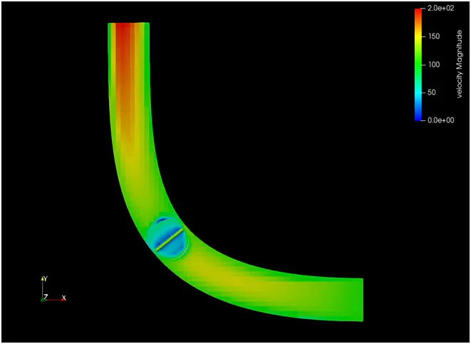
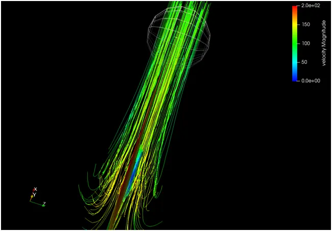
- At inlet, the velocity is low due to static pressure and then it begins to increase and reaches the yellow region.
- After that, the Throttle appears. This results in the low velocity over the throttle.
- Once it passes the Throttle, the velocity gets increasing and creates a parabolic form of high velocity at the area of the outlet.
At Throttle:
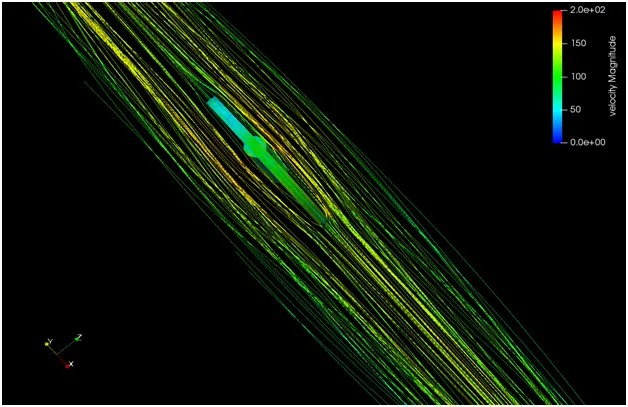
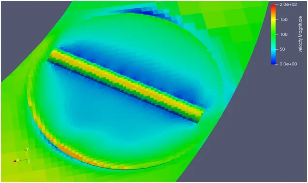
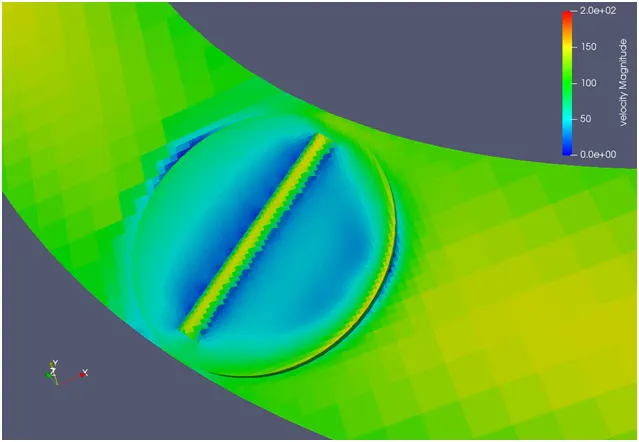
- At the inlet side of throttle, the velocity seems to be very low due to high pressure and over the surface of the Throttle also the velocity is low.
- So, from the streamline flow picture, at the edge of the throttle, the uninterrupted fluid flow inside the elbow wall has been divided into two interrupted fluid flows in the sides of the elbow wall by the Throttle plate.
- These two interrupted fluid flow flows over the shaft of the Throttle which creates high velocity (small portion of yellow region over the shaft) on the both sides of the shaft and it also causes the low velocity over the throttle plate.
- And it attaches over the another edge of the Throttle plate and it passes through the Elbow wall.
- Eventually, it reaches the parabolic form of high velocity at the area of the outlet.
- Since the Throttle plate has not been fully sealed to the elbow wall, the low velocity of air also appears to flow through the gap between the elbow wall and throttle plate.
Pressure:
At Elbow wall:
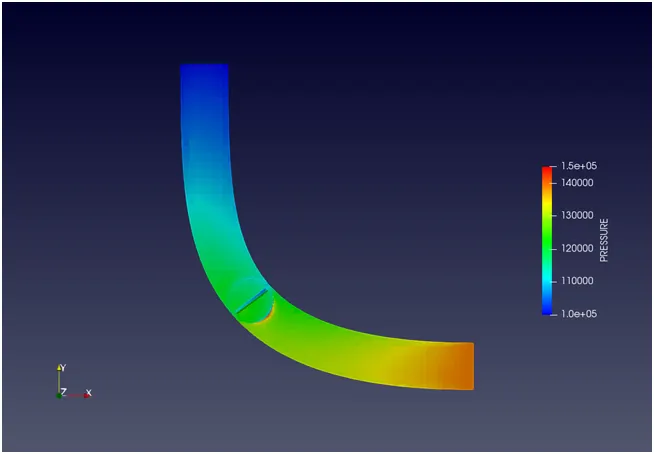
- At the area of inlet, the static pressure is high and as the cycles is going on the static pressure will be reducing due to the increase in dynamic pressure.
- At the area of the outlet, the pressure is too low since the velocity is high there.
At the Throttle plate:
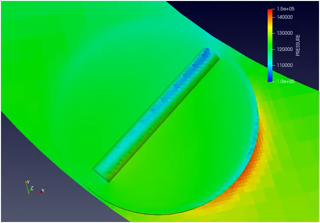
- At the inlet area of the throttle, the pressure is too high due to the strike of the high pressure air.
- According to Bernoulli’s principle, the high pressure air at the centre of the throttle plate flows to the both the side of the throttle plate and creates high velocity at that particular point where also creates low pressure and over the shaft, the velocity is bit high so that the pressure is also low.
- At the area of the outlet, the velocity will be high and so the pressure will be so low since the pressure is inversely proportional to velocity.
Conclusion:
- The flow of a throttle body will usually or mainly be simulated for the purpose of the flow of the inlet air to the engine where the throttle plate would be controlled either by mechanically or by the integrated chip in order to breathe particular amount of air-fuel to the engine.
- Here, the basic idea and CFD concepts of steady-state flow in this throttle body has been observed and learnt.
- The main purpose and idea of the fixed embedding and the mesh generation has been learnt.
Physical simulation by PARAVIEW:
Velocity animation: https://youtu.be/MGP0L1mhO_I
Pressure animation: https://youtu.be/dBNzqU0ekks