Section Modulus calculation and optimization
1) Every part that is designed and developed has to qualify not only in terms of aerodynamics but strength too. For aerodynamics, the design can be customized and reshaped for better air flow over the surface of the that panel. In the same way, the design also plays a key role in giving strength to the material. Of course, the material used plays a major role when it comes to strenght e.g. graphene which is newly created material which holds better properties than carbon fibre. It is lighter and stronger and at the same time very thin. Many electric automakers are going to replace this with the existing material due to the same advantages of graphene. Graphene has straight carbon chain compared to hexagonal chain of carbon fibre so it is a bit cheaper than the latter.

The pic shows the strength of graphene which is also known as 'miracle material'.
*) There are so many methods to test a designed part and one such is section modulus calculation. Section modulus comes under strength of materials.
*) It is defined as the ratio between the moment of inertia of cross section about the neutral axis and maximum distance of the fibre from the neutral axis. It is determined by the formula:-
*) It can denoted by Z or S.
Z or S=I/Y
*) Unit of moment of inertia is mm^4 and distance is mm so unit of 'Z' becomes mm^3.
*)
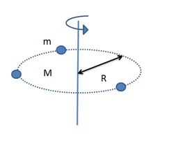
I is moment of inertia which is different from inertia. Inertia is associated to a case where the body would be having a translation motion of a motion in a straight line while moment of inertia comes into picture when angular motion or torque is applied. Both inertias do the same work of opposing the body whether it is in motion or state of rest. If the body is in motion then inertia would not allow it to stop immediately and if it is at rest then inertia won't allow it to move easily. Different shapes have different values of 'I'.
*)
Y is the distance from the origin on the co-ordinate system.
*) It is clearly seen that Z is directly proportional to I that means if the moment of inertia is more then the section modulus would also become more.
*) For e.g. rectangle section
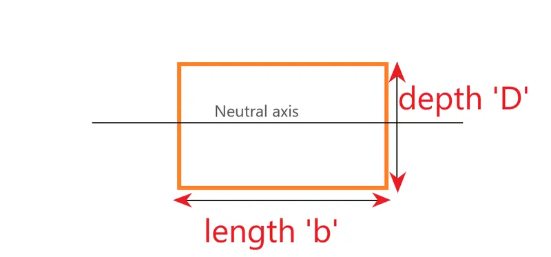
referring to the figure,
'I' will be (b*(D^3))/12 according to derivation
y= D/2
section modulus for a rectangular section is calculated as,
Z= (b*(D^2))/6
2) Case (i) Section modulus of the designed hood
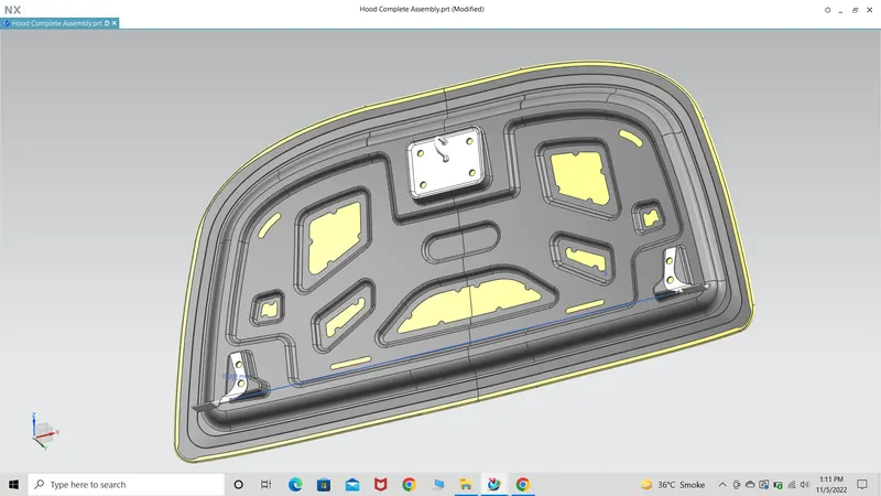
*) To find out section modulus of the given hood, first the 3D model needs to be converted into 2D sketch. The hood needs to be opened in NX12 and later hide hinge,striker and constraints. This is done because it is the outer and inner panel that has to be considered for 3D model to 2D sketch convertion.
*) With the help of curve intersection, the conversion is executed. In curve intersection, the 1st face is selected by choosing outer and inner panel at.
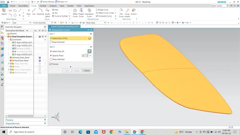
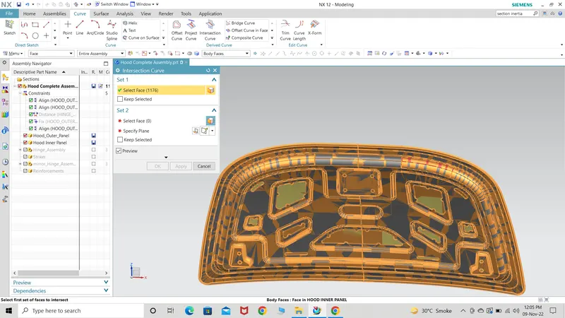
*) The plane is selected which creates a blue line on the cross section region. Hit OK.
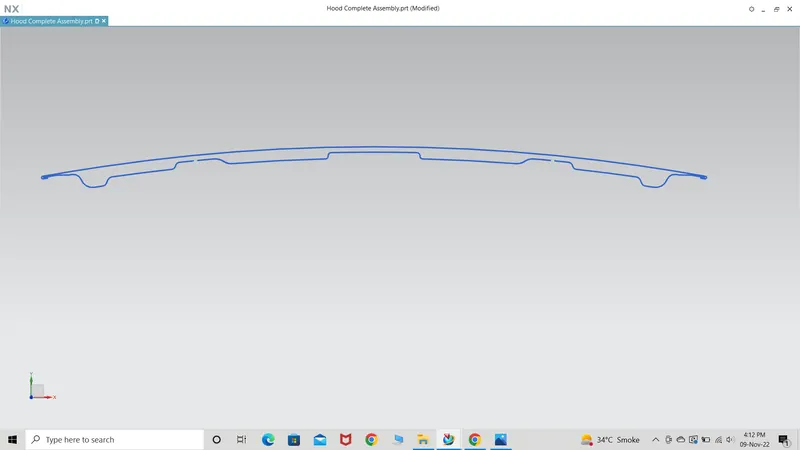
*) The 2D sketch is formed but it is having some gaps due to the designed I've adapted. Also due to thickness, there is outer and inner thickness lines for which the outer line of the outer panel and lower line of the inner panel. The section modulus can only be executed if the sketch is closed one so I complete the sketch by projecting it on this plane and edit the corners as well.
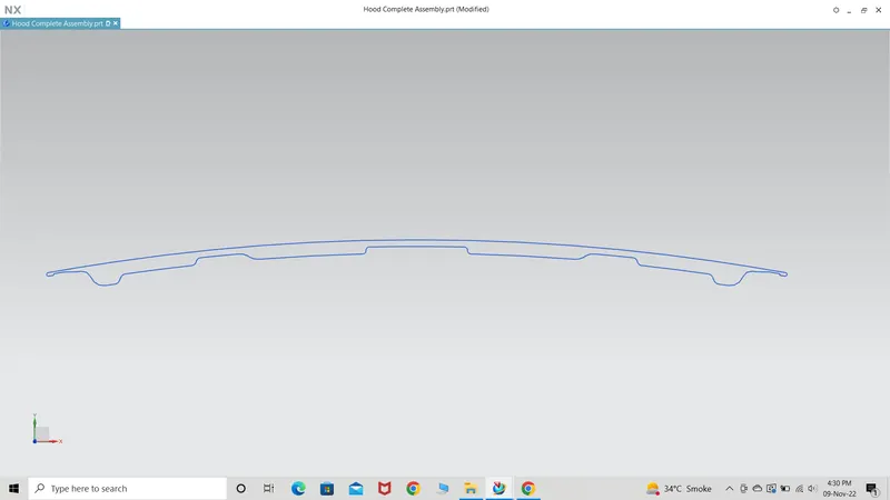
To connect the line always use studio spline because that would give the same type of geometry as is getting followed by the sketch on both the sides. If there is a curve then while connecting the same curve would be adapted and same goes for any other path traced by the line on both sides of the gap. If line is used then it would always form a straight linear line which is might not have any symmetry with the other traced lines.
*) While going for the section analysis, I've selected existing curve and in settings hollow with thickness 0.75mm as per the thickness of the panel is selected.
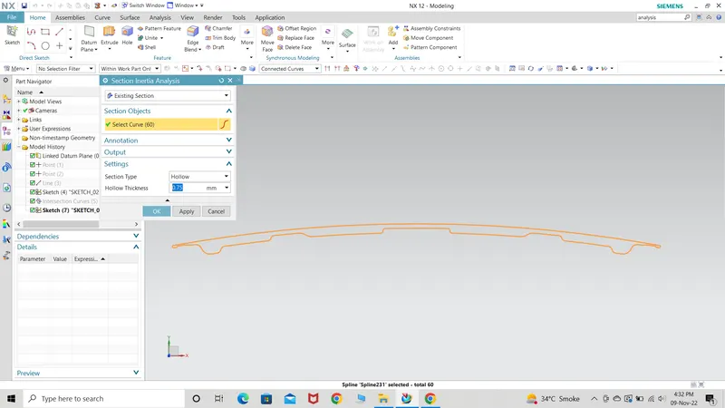
*) The values are getting displayed on the sketch itself which are later used for calculating the section modulus as per the formula.
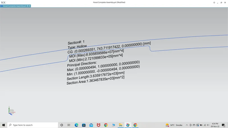
The value taken into consideration is the min moment of inertia which is 2.721099833e+05mm^4.
The length is also measured which is 903.202mm.
Case (ii) hood with added emboss region.
To improve the stiffness of the hood, it's rigidity has to be improved which would ultimately improve the overall strength of the hood. This can be done in two ways 1) Increase the moment of inertia by increasing the area of the hood 2) reduce the distance of the outer fibre. We cannot change the length of the panel but surely we can improve the area by giving another embossing region.
*) I've edited the sketch and created a 2D sketch which would resemble a emboss if viewed in 3D model view.
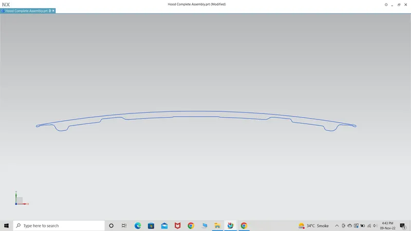
*) After running section inertia analysis, the following data is displayed where it is clearly visible that by increasing the area MOI has increased.
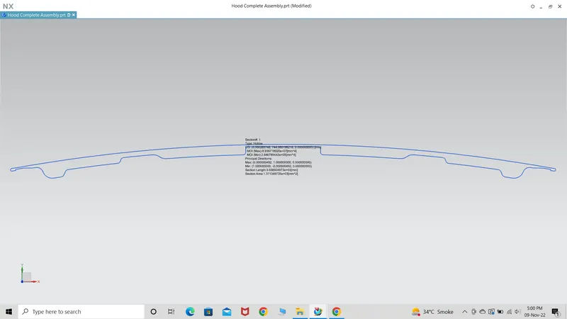
The value taken into consideration is the min moment of inertia which is 2.846789442e+05mm^4.
The length is also measured which is 903.202mm.
The section area was increased from 1.363467835e+03mm^2 to 1.371349735e+03mm^2.
The values are used to find the section modulus.
1) Section modulus of case 1 = (2.721099833e+05mm^4/903.202)=301.27mm^3 .
2) Section modulus of case 2 = (2.846789442e+05mm^4/903.202)=315.188mm^3.
The result show that the strength of the modified section has jumped up to a certain value making the panel stiffer,rigid and strong.