Section Modulus calculation and optimization
AIM
To calculate the section modulus of the previously designed hood for analysing its strength and also optimising the design to see the difference in bending strength of hood. higher the section modulus the more ressitive it becomes to bending.
SECTION MODULUS
Sectin moduls is a geometric property for a given cross section used for the design of beams or fluxual members. Other geometric properties used in design include area for tension and shear, raius of gyration for compression, and moment of inertia and polar moment of inertia for stiffness. Any relationship between these properties is highly dependent on the shape in question. Equations for the section moduli of common shapes are given below. There are two types of section moduli, the elastic section modulus and the plastic section modulus. The section moduli of different profiles can also be found as numerical values for common profiles in tables listing properties of such.
S = I/Y
where,
S is section modulus,
I - moment of inertia
Y - Distance from the neutral axis to the extreme end

ELASTIC SECTION MODULUS
For general design, the elastic section modulus is used, applying up to the yield point for most metals and other common materials.
The elastic section modulus is defined as S = I / y, where I is the second moment of area (or area moment of inertia, not to be confused with moment of inertia) and y is the distance from the neutral axis to any given fibre. It is often reported using y = c, where c is the distance from the neutral axis to the most extreme fibre, as seen in the table below. It is also often used to determine the yield moment (My) such that My = S ⋅ σy, where σy is the yeild strength of the material.
SECTION MOULUS EQUATIONS
A
| Cross-sectional shape | Figure | Equation | Comment |
|---|---|---|---|
| Rectangle | {\displaystyle S={\cfrac {bh^{2}}{6}}} |
Solid arrow represents neutral axis | |
| doubly symmetric I-section (major axis) | {\displaystyle S_{x}={\cfrac {BH^{2}}{6}}-{\cfrac {bh^{3}}{6H}}}
{\displaystyle S_{x}={\tfrac {I_{x}}{y}}} with {\displaystyle y={\cfrac {H}{2}}} |
NA indicates neutral axis | |
| doubly symmetric I-section (minor axis) | {\displaystyle S_{y}={\cfrac {B^{2}(H-h)}{6}}+{\cfrac {(B-b)^{3}h}{6B}}} [4] [4] |
NA indicates neutral axis | |
| Circle | {\displaystyle S={\cfrac {\pi d^{3}}{32}}} [3] [3] |
Solid arrow represents neutral axis | |
| Circular hollow section | {\displaystyle S={\cfrac {\pi \left(r_{2}^{4}-r_{1}^{4}\right)}{4r_{2}}}={\cfrac {\pi (d_{2}^{4}-d_{1}^{4})}{32d_{2}}}} |
Solid arrow represents neutral axis | |
| Rectangular hollow section | {\displaystyle S={\cfrac {BH^{2}}{6}}-{\cfrac {bh^{3}}{6H}}} |
NA indicates neutral axis | |
| Diamond | {\displaystyle S={\cfrac {BH^{2}}{24}}} |
NA indicates neutral axis | |
| C-channel | {\displaystyle S={\cfrac {BH^{2}}{6}}-{\cfrac {bh^{3}}{6H}}} |
NA indicates neutral axis |
 ,
,
PLASTIC SECTION MODULUS
The plastic section modulus is used for materials where elastic yielding is acceptable and plastic behavior is assumed to be an acceptable limit. Designs generally strive to ultimately remain below the plastic limit to avoid permanent deformations, often comparing the plastic capacity against amplified forces or stresses.
The plastic section modulus depends on the location of the plastic neutral axis (PNA).The PNA is defined as the axis that splits the cross section such that the compression force from the area in compression equals the tension force from the area in tension. So, for sections with constant yielding stress, the area above and below the PNA will be equal, but for composite sections, this is not necessarily the case.
The plastic section modulus is the sum of the areas of the cross section on each side of the PNA (which may or may not be equal) multiplied by the distance from the local centroids of the two areas to the PNA:

The Plastic Section Modulus is not the 'First moment of area'. Both relate to the calculation of the centroid, but Plastic Section Modulus is the Sum of all areas on both sides of PNA (Plastic Neutral Axis) and multiplied with the distances from the centroid of the corresponding areas to the centroid of the cross section, while the First moment of area is calculated based on either side of the "considering point" of the cross section and it is different along the cross section and depends on the point of consideration.
The plastic section modulus is used to calculate the plastic moment, Mp, or full capacity of a cross-section. The two terms are related by the yield strength of the material in question, Fy, by Mp = Fy ⋅ Z. Plastic section modulus and elastic section modulus are related by a shape factor which can be denoted by k, used for an indication of capacity beyond elastic limit of material. This could be shown mathematically with the formula :-

Shape factor for a rectangular section is 1.5.
DESIGN STUDY:
CASE 1: BEFORE OPTIMISATION
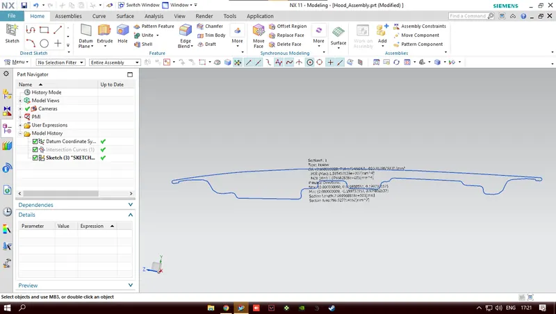
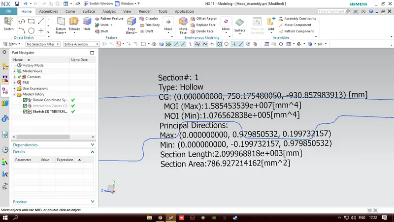
MOI(Max) = 1.585453539e+007 mm^4
MOI(Min) = 1.076562838e+005 mm^4
As per section modulus equation;
S = I/Y
I = MOI(Min) value is considered
Y = Total distance/2
Total distance = 489.1
Y = 489.1/2 = 244.55 mm
therefore
S = 1.076562838e+005 mm^4/ 244.55 = 440.2219 mm^3
CASE 2: AFTER ADDING AN EMBOSS
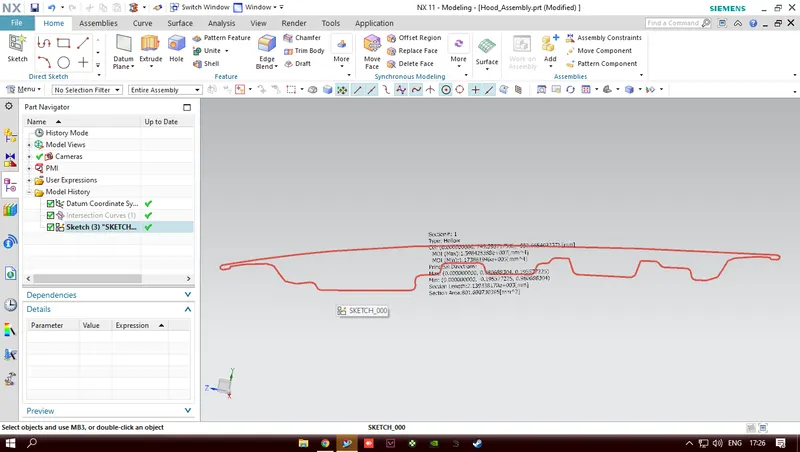
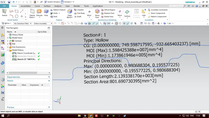
MOI(Max) = 1.598425388e+007 mm^4
MOI(Min) = 1.173861946e+005 mm^4
As per section modulus equation;
S = I/Y
I = MOI(Min) value is considered
Y = Total distance/2
Total distance = 489.1
Y = 489.1/2 = 244.55 mm
therefore
S = 1.173861946e+005 mm^4/ 244.55 = 480.0089 mm^3
CONCLUSION: HENCE BY COMPARING CASE 1 AND 2 WE COME TO THE RESULT THAT THE SECTION MODULUS OF CASE 2 IS HIGHER THAN THAT OF CASE 1 ALSO, BY INCREASING THE AREA OF THE SECTION, THE MOMENT OF INERTIA AND THE SECTION MODULUS INCREASES AND LOAD MATERIAL ALSO INCREASES.