Section Modulus calculation and optimization
SECTION MODULUS CALCULATION AND OPTIMIZATION
Our next challenge is to calculate the section modulus for the hood design using the formula:-
S = I / y
Where,
S = Section Modulus
I = Moment of Inertia
y = Distance between the neutral axis and the extreme end of the object.
But before starting the challenge we get to know what actually the section modulus is and for what purpose it is calculate.
- WHAT IS SECTION MODULUS?
- Section modulus (S) is the ratio of moment of inertia (I) of the component cross section from the neutral axis of the component to the distance y maximum of the extreme fiber.
- In simple words the section modulus gives us an idea about the designed component that how much load it can bear. i.e it gives us the load bearing capacity of the component.
- The purpose of the section modulus calculation is that it helps us to calculate the load bearing capacity of the object.
Well now we got pretty much clear what actually the section modulus is and why it is calculated.
Now let’s jump into the challenge part. Here we need to calculate the section modulus of the hood design which we have designed earlier as shown in the figure below.
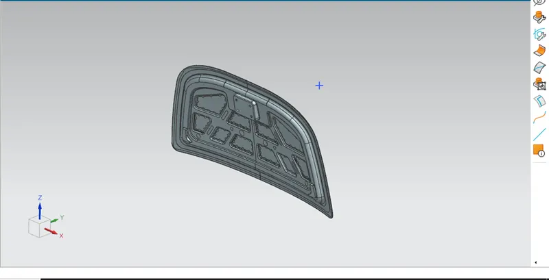
Here we have both hood inner panel and the outer panel.
So initially we need to take the intersection of the center plane with the hood part as shown in the figure below.
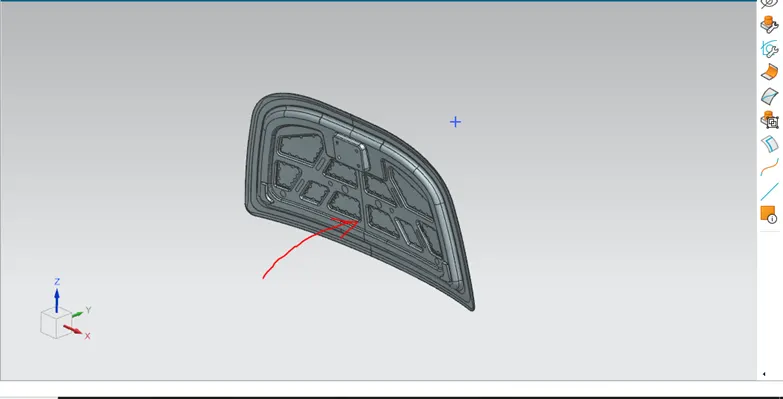
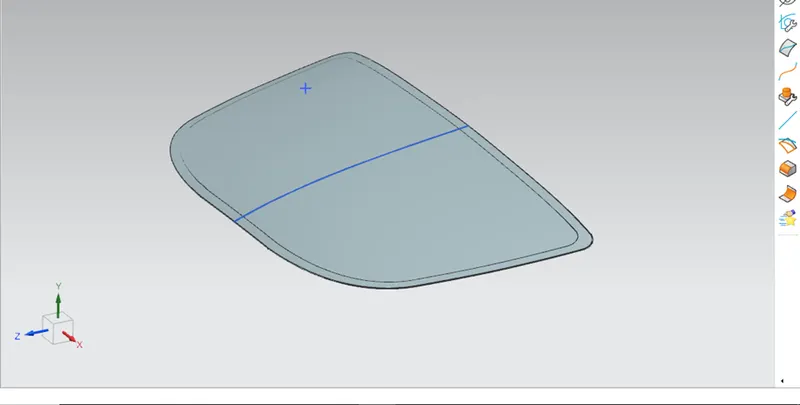
We get the curve as shown in the figure.
Hide the component and start the sketch on the center plane as shown in the figure below.
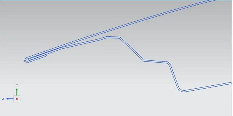
As we start the sketch we can be clearly able to see that here the curve have the thickness.
So here only the outer panel curve outer surface and the inner panel curve outer surface was kept and rest all the sketch is been erased.
Now the inner panel and the outer panel is not connected so here the lines are drawn and the sketch is fully closed from both the sides.
Now the main part comes into the work here as the sketch is closed we need to calculate the moment of inertia. So the section inertia analysis command is used to calculate the inertia of the hood as shown in the figure below.
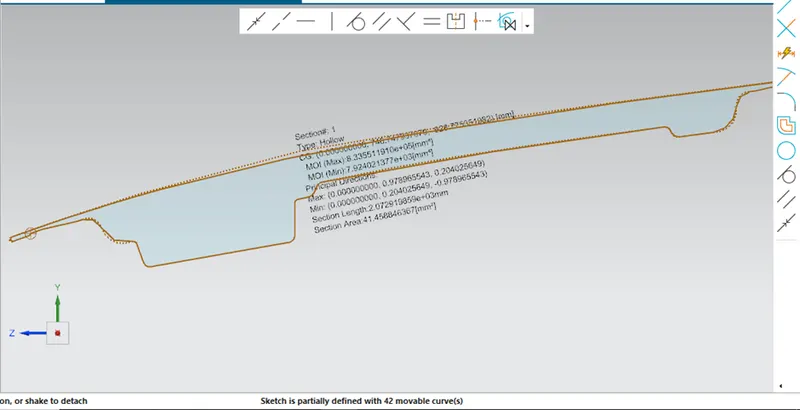
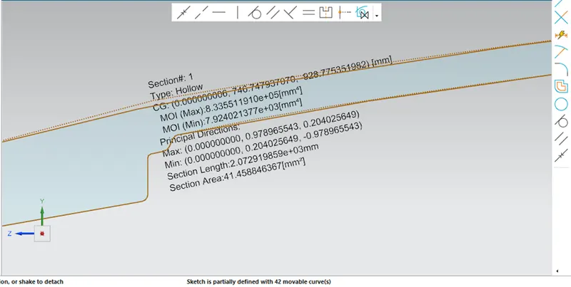
So as we can clearly see that the moment of inertia of the hood design is shown in the above figure.
Maximum moment of inertia is :- 8.335511 x 105 mm4.
Minimum moment of inertia is :- 7.924021 x 103 mm4.
Here our first part gets complete we have calculate the moment of inertia.
Our next task is to find the Y maximum distance from the neutral axis i.e from the center of the component. So here the two points are drawn at the two extreme ends of the intersection sketch. And then the lines are drawn vertically then the distance is calculate between the two ends points.
And finally the total distance is divided by 2 to get the y maximum value as shown in the figure below.
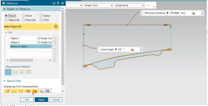
As we can see in the above figure the total distance showing between the extreme ends is 478.4668mm.
Now to find the y maximum,
Y maximum = D / 2
= 478.4668 / 2
= 239.2334 mm
We got the y maximum as 239.2334 mm.
So well we have the moment of inertia (I) as well as the y maximum value, so let’s calculate the section modulus (S) for the initial design of the hood.
Section Modulus (S) = I / y
Here the minimum value of the moment of inertia is considered.
= 7.924021 x 10³ / 239.2334
= 33.12255 mm4.
So for the initial design of the hood we get the section modulus (S) as 33.12255 mm4.
Now we need to justify that our design is eligible to handle the load i.e we need to check that this design of hood has the best load bearing capacity or not. Here we need to do some changes in the initial design in order to check which design of the hood will have the best value of (S) and then compare the results with the initial design results.
Here to do changes in the initial design means we need to do the optimization of the design and find out the values and then compare.
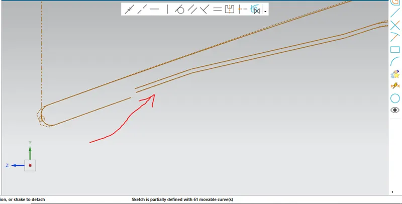
As we can see here the inner panel curve is been offset at 0.5mm in the downward direction in order to optimize the design and to check if we get the better results than the initial results.
Now the initial curve is been delete and then the lines are join to create the closed structure as shown in the figure below.
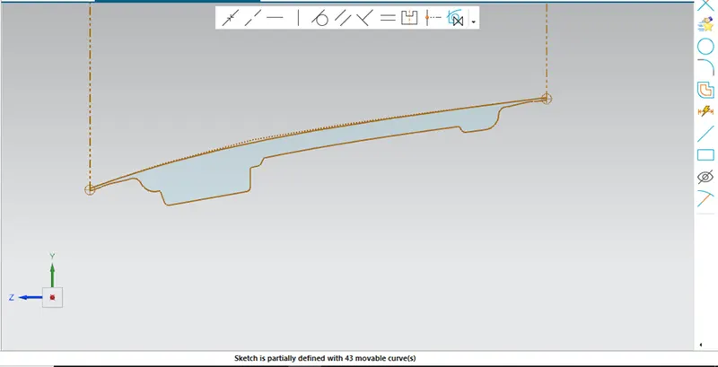
Now we need to do the section inertia analysis to find the moment of inertia of the optimized design.
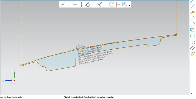
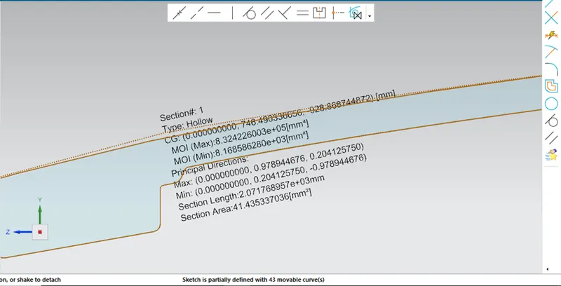
Now we can clearly see the moment of inertia of the optimized design as follows:-
Maximum moment of inertia is = 8.324226 x 105 mm4.
Minimum moment of inertia is = 8.168586 x 103 mm4.
Now as we have the moment of inertia of the optimized design and also the y maximum value let’s find out the section modulus (S).
So as we know,
S = I / y
Here the moment of inertia value is taken minimum to get the better results.
= 8.168586 x 10³ / 239.2334
= 34.1448 mm4.
So here we get the value of the section modulus (S) is 34.1448 mm4.
So as we have the results now we need to compare the design which one is efficient and have good strength ability against the force exerted on it.
|
Title |
Maximum moment of inertia (I) |
Minimum moment of inertia (I) |
Y maximum value (y) |
Section modulus (S) |
|
Initial hood design |
8.335511 x 105 mm4. |
7.924021 x 103 mm4. |
239.2334 mm. |
33.12255 mm4. |
|
Optimized hood design |
8.324226 x 105 mm4. |
8.168586 x 103 mm4. |
239.2334 mm. |
34.1448 mm4. |
So now from the above table we can analyze the values and can see that the initial hood design have the section modulus value (S) is 33.12255 mm4, whereas the optimize design have the better section modulus value (S) 34.1448 mm4.
So by visualizing the results we can say that the load bearing capacity of the optimized design is better than the initial design as it have the section modulus value greater than initial design value.
To conclude this, here we just have increased the offset distance i.e the distance between inner panel and outer panel of the design by 0.5mm and we got the better results than initial design. To make our design efficient and stronger we need to increase the distance between the inner panel and outer panel.