Section Modulus calculation and optimization
WHAT IS SECTION MODULUS ?
Before,starting about section modulus we need to know about FLEXURAL EQUATION.
M/I=σ/Y=E/R
M:Bending moment (N-mm)
I : Area Moment of inertia (mm∧4)
σ : Bending stress(N/mm∧2).
Y: distance of external fiber from Neutral axis.
E: young's modulus or modulus of elasticity (N/mm∧2).
R: Radius of curvature (mm).
The flexural equation is derived on the basis of "simple bending of Beam".
Assumptions considered for simple bending are:
- The beam is initially straight.
- The beam has constant cross sectoonal area with an axis of symmetry.
- The material of the beam is homogeneous and isotropic.
- Hooke's law is obeyed at all points.
- Plane transverse section remains plane and normal after bending.
- Young's modulus (E) of material is same in tension and compression.
- Every layer of material is free to expand or contract longitudinally and laterally under stress,and do not exert pressure upon each other. Thus, the poisson's effect and the interference of the adjoining differently stressed fires are ignored.
The beam section should have sufficient strength to resist external bending moment.To ensure strength of beam,it is necessary that the greatest tensile and greatest compressive stresses at critical section, should not exceed their corresponding allowable stresses for the material.
section modulus is the ratio of max.Bending moment to area moment of inertia.
The greater the section modulus greater the strength against bending.
HOOD ASSEMBLY
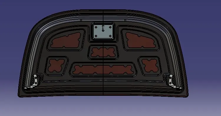
CALCULATION OF SECTION MODULUS FOR FRONTAL CRASH CONSIDERATION EXPLAINED IN BELOW STEPS:
STEP 1
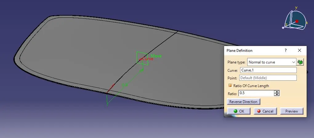
As shown in above image the datum plane is created by using Normal to curve option in plane type with ratio of curve length option value of 0.5.
STEP 2
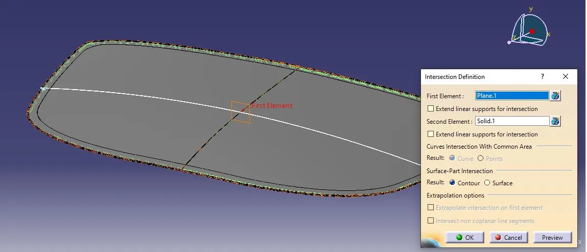
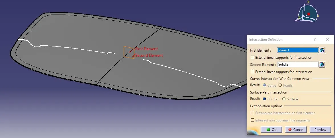
Using INTERSECTION CURVE option sections are generated from outer & inner panel simultaneously.
STEP 3

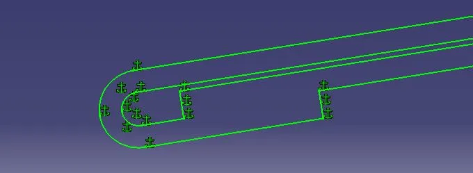
selecting the same datum plane for sketch,later on projecting the intesection curves obtained through previous steps.after, projecting those profiles isolating them individually.
trimming the unnecessary entities and closing the sections using spline command.
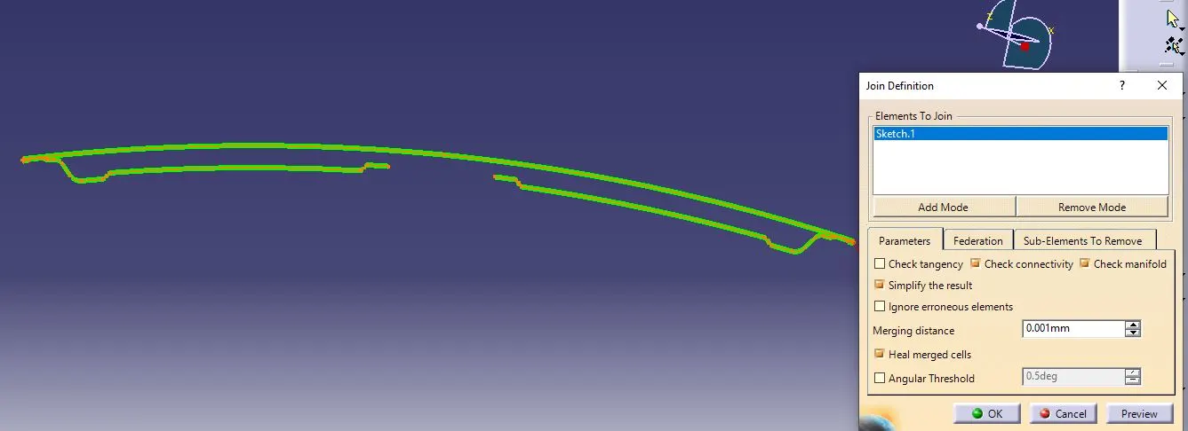
After completing the sketch,the join command is used to make it an single entity,followed to it it is smoothened by using curve smooth command.
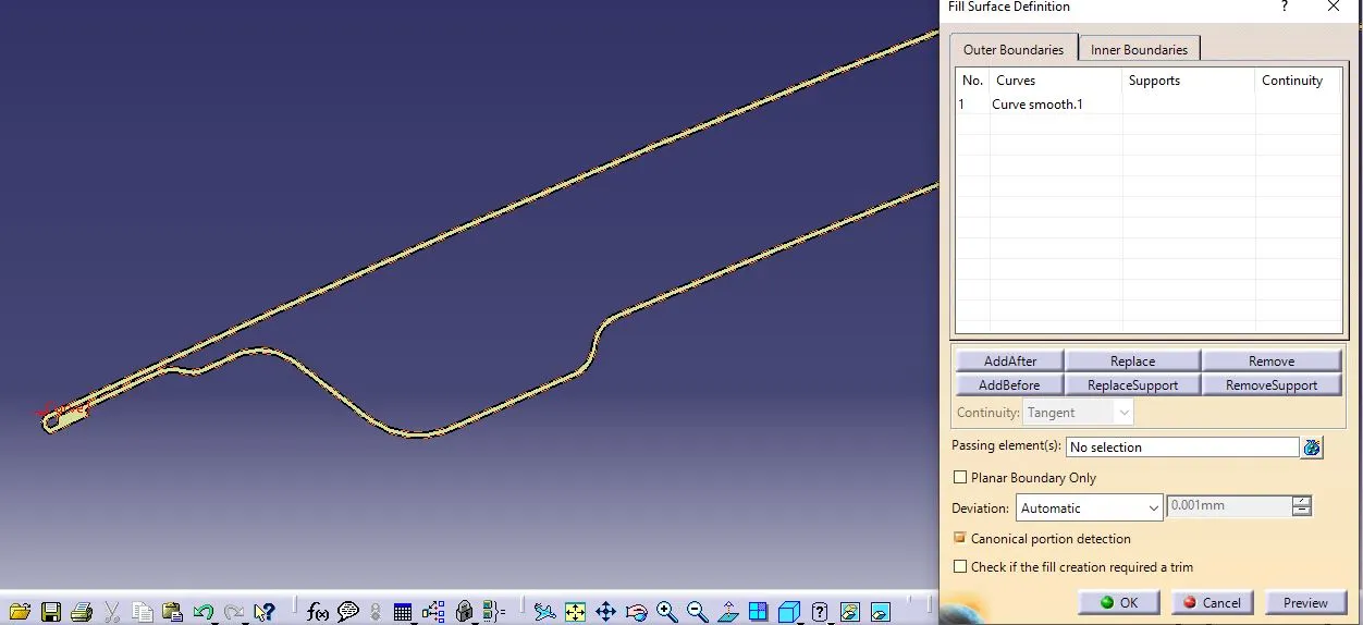
Those smooth curve are then filled using fill command as shown below.
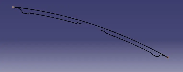
For checking the extreme ends for obtaining distance,points are created on "join curves"using point on curve.
Now, from measure inertia option using 2D section option and then selecting filled surface & the result of it are shown below.
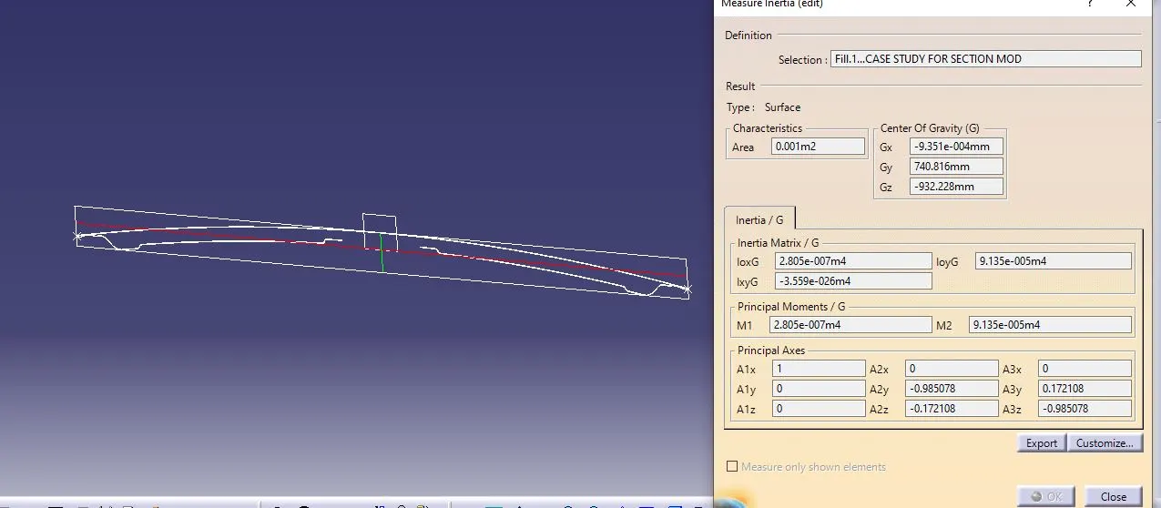
The above image shows the principle inertia of 2.805×10^-7 (in m^4)=2.805×10^5(in mm^4).
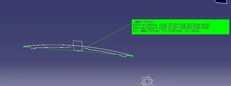
Now Y=885.7/2=443 mm
Z = I/Y = (2.805×10^5)/443=633.18 mm^3.
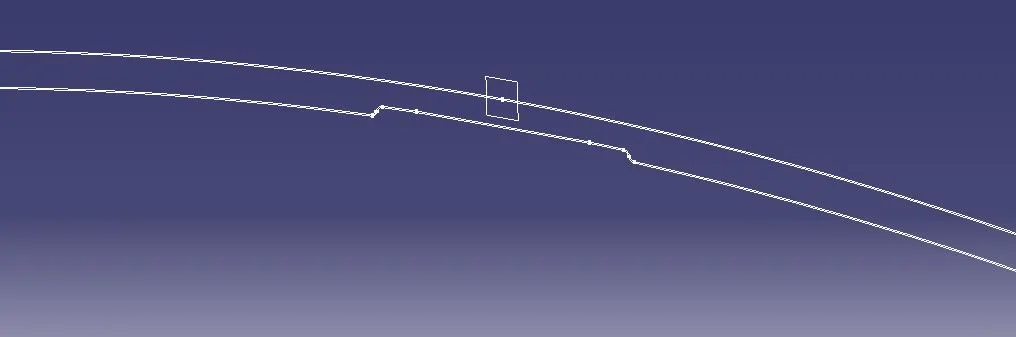
Now, to improve sectional strength. Simply considering same plane for sketch and using projecting 3d elements option join curves are projected on datum plane in that sketch later on isolating it and joining the middle portion using spline command.
Now,using extrude command the curves are extruded and the result of it as shown below.
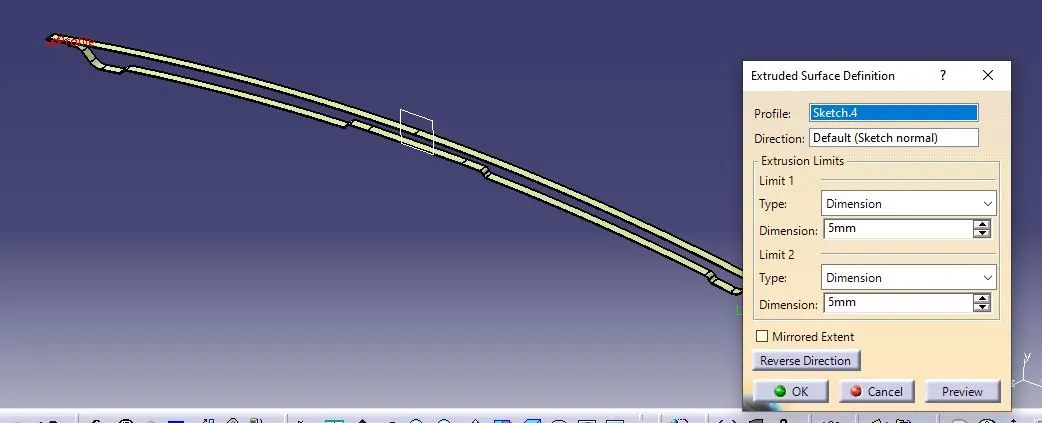
Now,one another line sketch is created and it is extruded in Lateral direction.
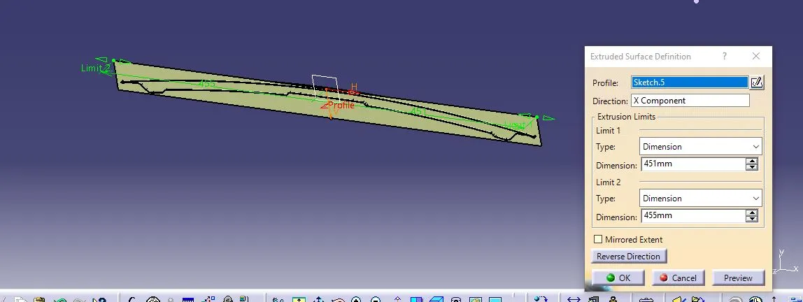
Those extruded surface are dismembered into two entities and using each individually split is done.
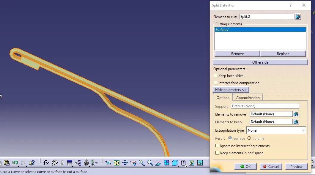
and we obtain the final result.
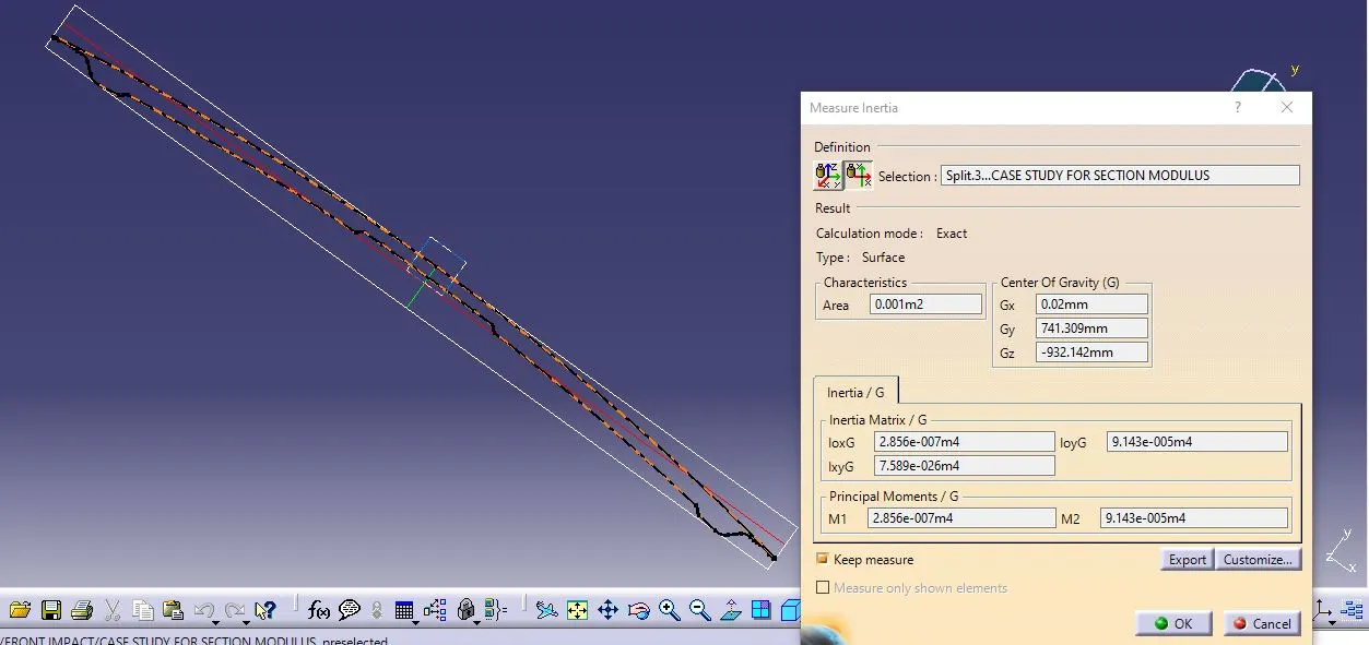
In similar manner as done previously we obtain the inertia result.
I=2.856×10^-7 (m^4)=2.856×10^5(mm^4)
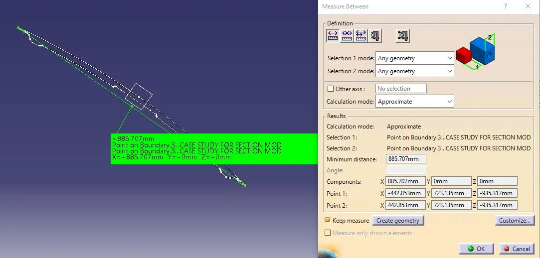
Y=443 mm
Z=I/Y=(2.856×10^5)/443=644.69 mm^3.
644.69 > 633.18
CALCULATION OF SECTION MODULUS FOR SIDE IMPACT CRASH AS BELOW :
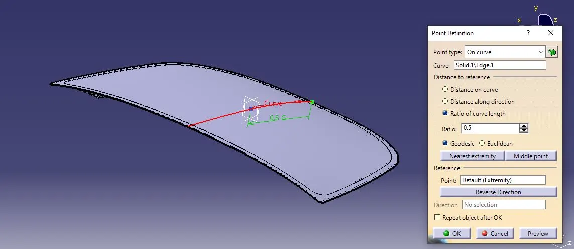
The datum plane is created using plane type on curve & 0.5 ratio of curve length.
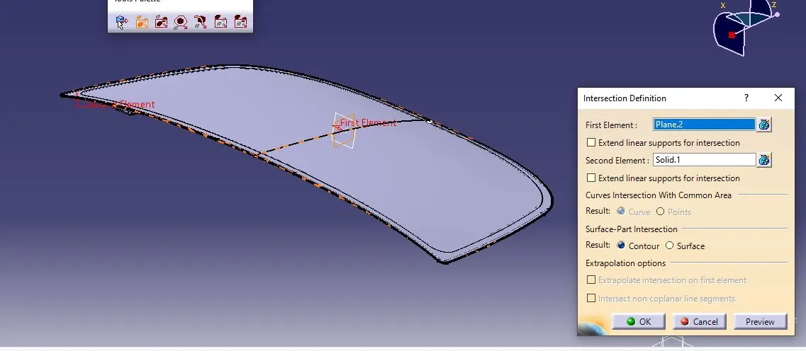
Now,intersection command is used simultaneously for outer panel and inner panel respectively.
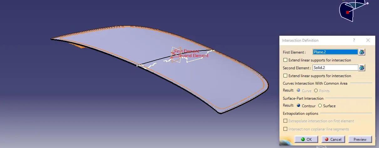
Those intersected profiles are then projected on new sketch developed using same datum plane.those sketches are then isolated and all entities are fix constrained.
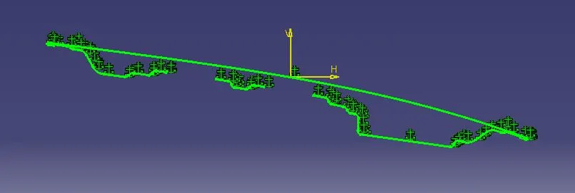
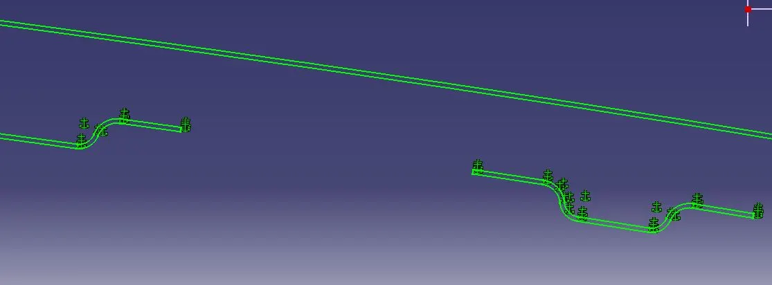
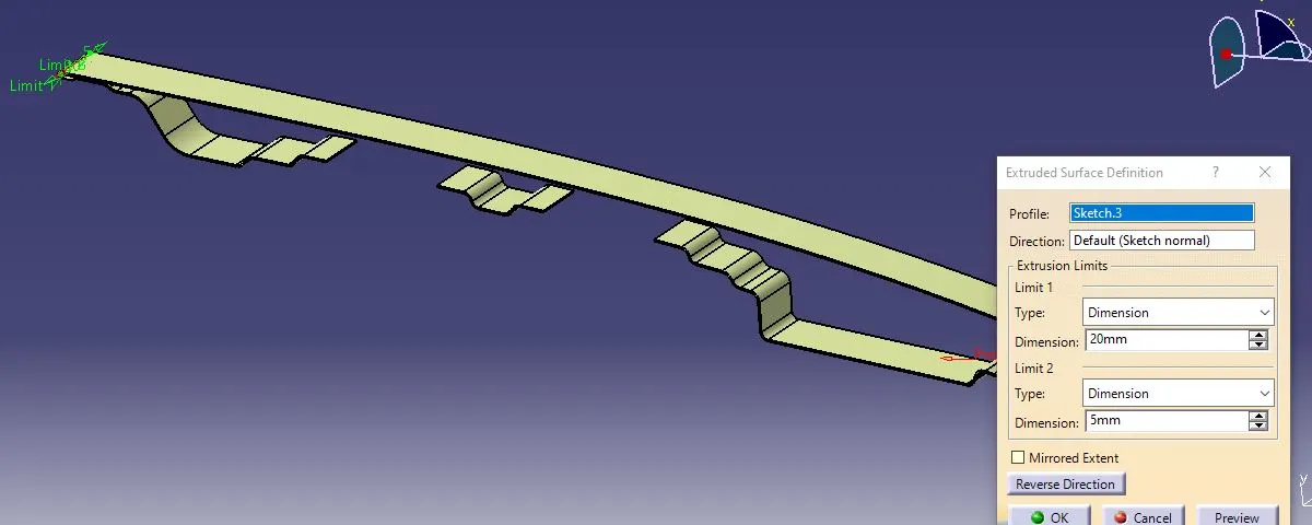
Those profiles then extruded using extrude command.
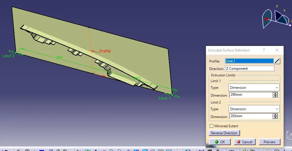
Now,again one line sketch is then extruded
Split option is used to split the extruded profile and another plane surface.
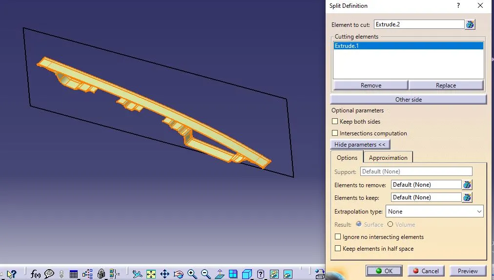
The result of it are obtained below.
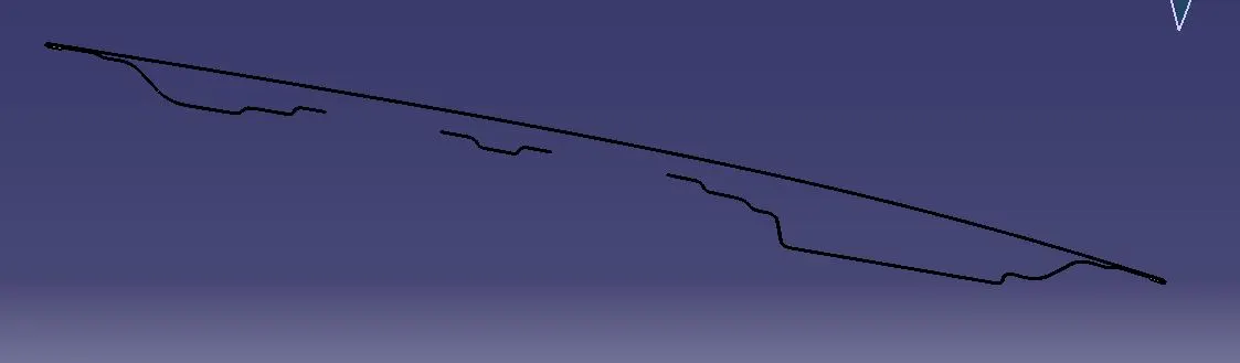
The boundary is created to create two points for measuring the Y distance.
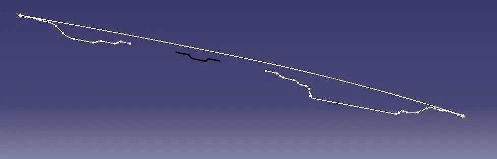
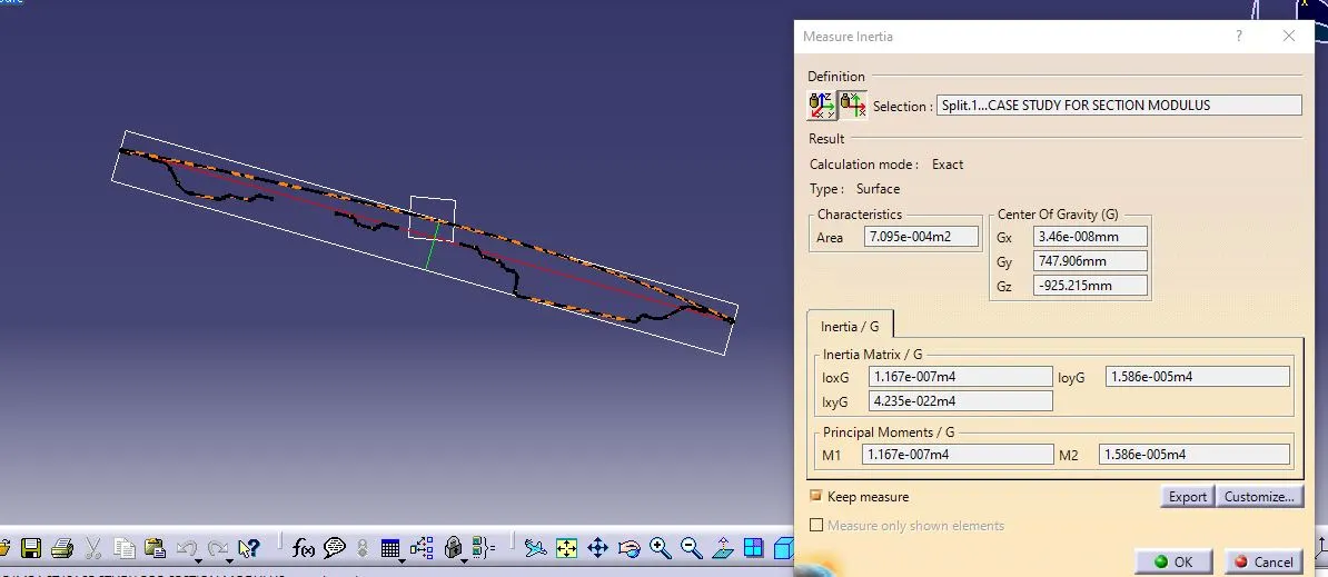
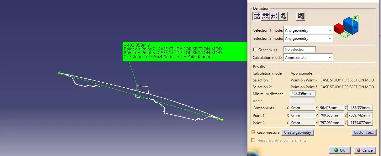
From above images,
I=1.167×10^-7(m^4)=1.167×10^5(mm^4).
Y=492.859/2= 247 mm
Z=I/Y=472.47 mm^3
In order to improve the section strength again a sketch is created on same datum plane and both intersection curves are again projected,they are trimmed and joined using spline command.
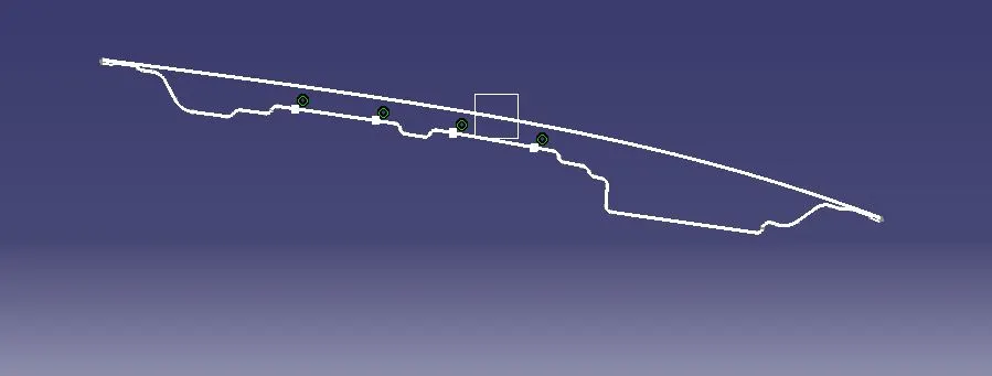
The sketch is then extruded using extrude command the result of it as shown below.
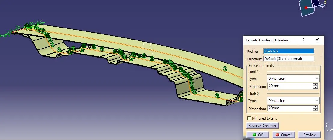
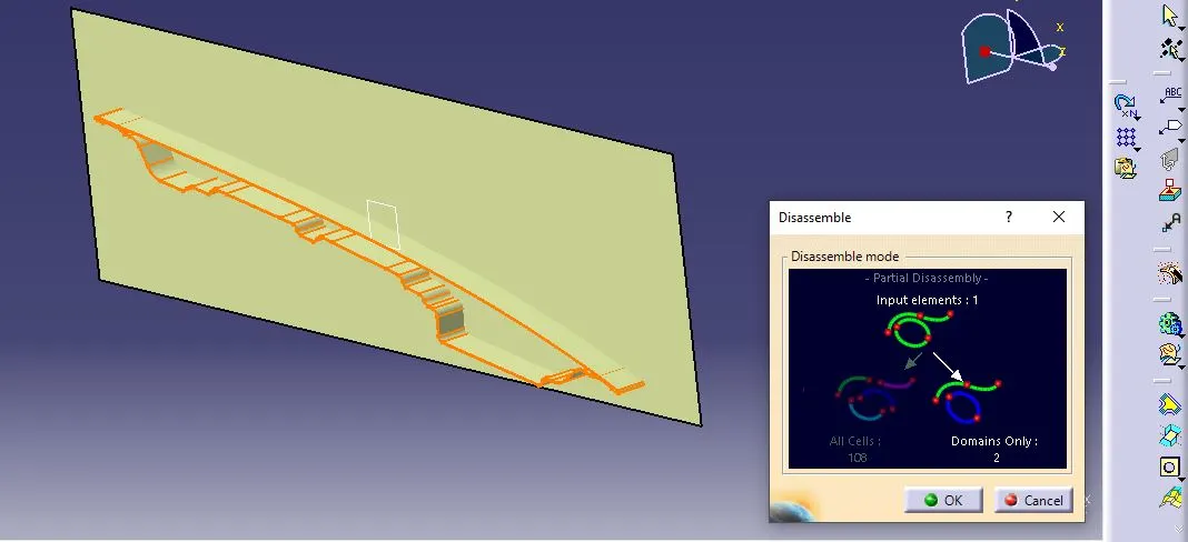
As done in previous scenarios same flat plane is used for splitting and before splitting it the extruded profiles are dismembered in two domains.as shown below.
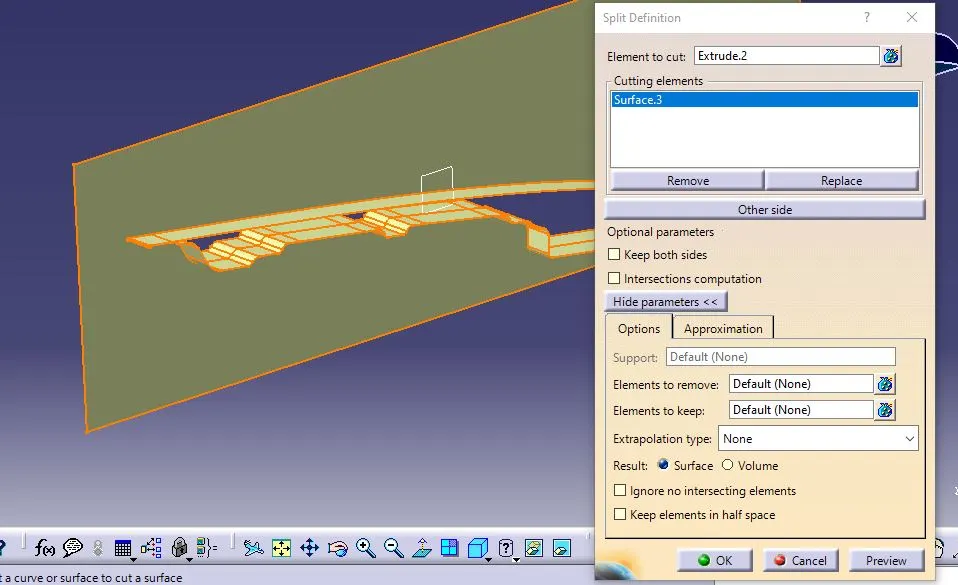
Splitting is done simultaneously considering inner and outer surface simultaneously. The results of it as shown below.
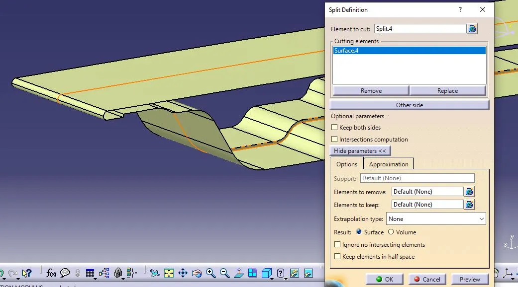
The split is then measured using measure inertia option as shown below.
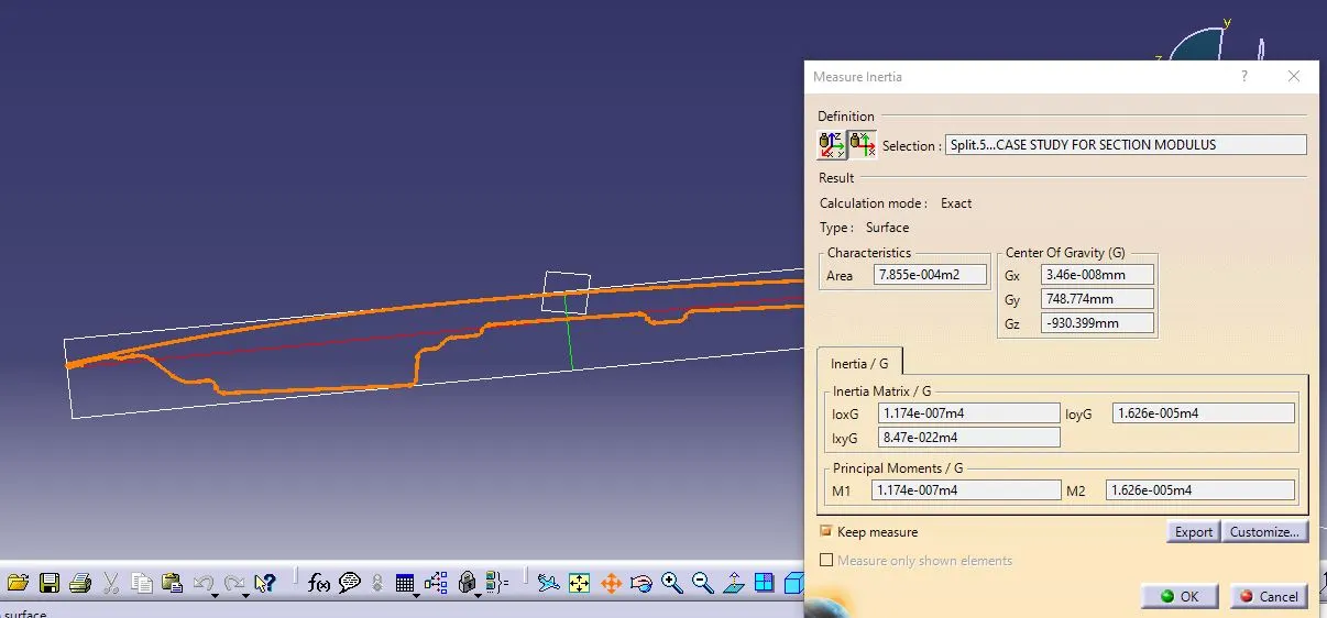
I= 1.174×10^-7(m^4)=1.174×10^5(mm^4).
Y=247 mm
Z=I/Y=1.174×10^5/247=475.3 mm^3
475.3 > 472.47