Section Modulus calculation and optimization
Section Modulus calculation and optimization
Aim:- To calculate the section modulus of the previously designed hood for analyzing its strength and also optimizing the design to see the difference in the bending strength of the hood. Higher the section modulus of a structure, the more the resistive it becomes to bending and higher will be the strength.
Section Modulus
Section modulus is a geometric property for a given cross-section used in the design of beams or flexural members, it is also referred to as the Polar Modulus or the Torsional Sectional Modulus. Other geometric properties used in design include area for tension and shear, radius of gyration for compression, and moment of inertia and polar moment of inertia for stiffness. Any relationship between these properties is highly dependent on the shape in question. Equations for the section moduli of common shapes are given below. There are two types of section moduli, the elastic section modulus and the plastic section modulus.
S=I/Y
Here,
S = Section modulus
I= Moment of Inertia (Unit mm 4)
Y= Distance from Neutral axis to the extreme end (unit mm)
The Unit of a “section modulus” is (mm3)
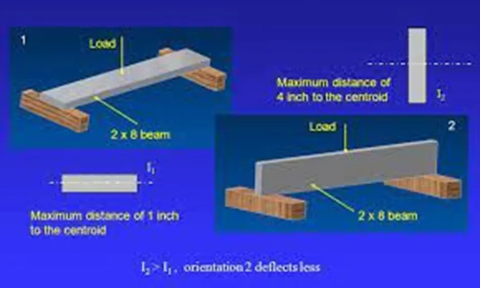
Take these considerations into account when calculating section modulus and maximum stresses:
- We obtain the bending moment through a static or structural analysis of the beam.
- To get the section modulus, we can use tables for predefined structural members, but this calculator is the best option if you're dealing with custom geometries.
- If we're considering a uniform section beam (as usual), the location of the maximum stress will be at the point of maximum bending moment. If that's not the case, σm could be at a different place.
- The previous formulas apply to materials that exhibit an elastic behavior and obey Hook's law. When there's plastic deformation instead of elastic deformation, we need to use the plastic section modulus.
Plastic section modulus
The plastic section modulus is used for materials where elastic yielding is acceptable and plastic behavior is assumed to be an acceptable limit. Designs generally strive to ultimately remain below the plastic limit to avoid permanent deformations, often comparing the plastic capacity against amplified forces or stresses.
The plastic section modulus depends on the location of the plastic neutral axis (PNA). The PNA is defined as the axis that splits the cross section such that the compression force from the area in compression equals the tension force from the area in tension. So, for sections with constant yielding stress, the area above and below the PNA will be equal, but for composite sections, this is not necessarily the case.
The plastic section modulus is the sum of the areas of the cross section on each side of the PNA (which may or may not be equal) multiplied by the distance from the local centroids of the two areas to the PNA:
<!-- [if mso & !supportInlineShapes & supportFields]> SHAPE \* MERGEFORMAT <![endif]--><!-- [if gte vml 1]>
the Plastic Section Modulus can also be called the 'First moment of area'
The plastic section modulus is used to calculate the plastic moment, Mp, or full capacity of a cross-section. The two terms are related by the yield strength of the material in question, Fy, by Mp=Fy*Z. Plastic section modulus and elastic section modulus are related by a shape factor which can be denoted by 'k', used for an indication of capacity beyond elastic limit of material. This could be shown mathematically with the formula :-
<!-- [if mso & !supportInlineShapes & supportFields]> SHAPE \* MERGEFORMAT <![endif]--><!-- [if gte vml 1]>
shape factor for a rectangular section is 1.5.
So here we are Calculating Elastic section Modulus
Initial Design Study
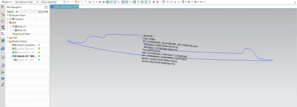
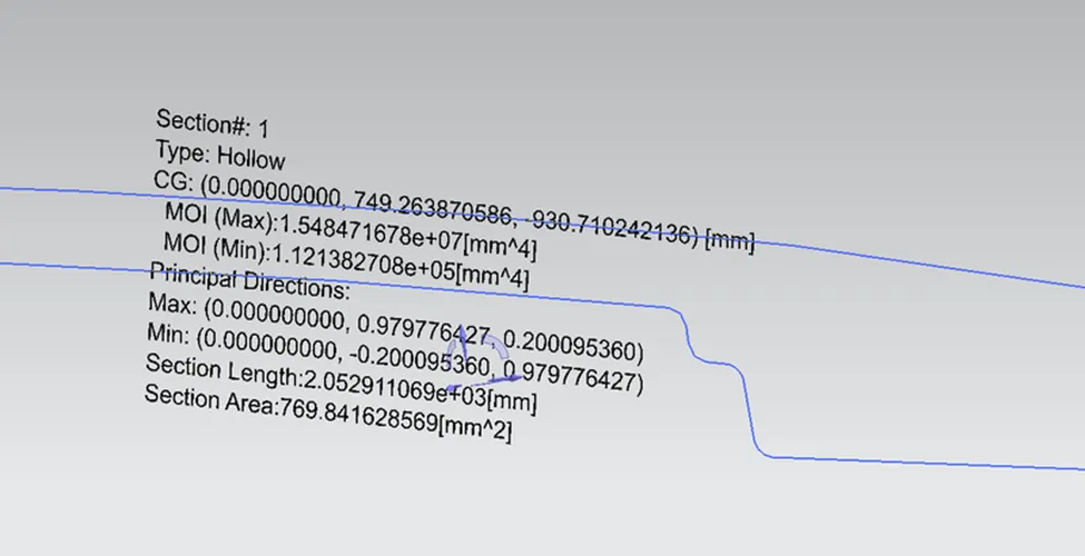
Here the moment of inertia was calculated by using the NX-software obtained values are
IMAX:- 1.54847X107mm4
Imin:- 1.12138x105mm4
Total length of 'Y' value was 487.4152mm
So,at neutral axis we need 'Y' value:-Y/2=487.4152/2=243.7076mm
1)Section modulus(S):-I/Y= 1.54847X107mm4/243.7076mm
= 63.354X103mm3(Maximum strength).
2) Section modulus(S):-I/Y=1.12138x105mm4/243.7076mm
= 460.133mm3(minimum strength).
Hood Design Optimization
By increasing the depth of the inner panel by 2 mm
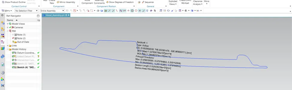
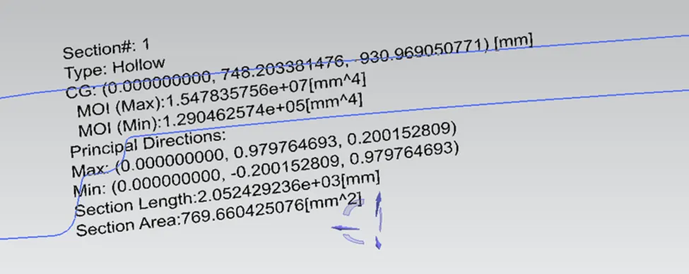
Here the moment of inertia was calculated by using the NX-software optimized values are
IMAX:- 1.54783X107mm4
Imin:- 1.29046x105mm4
Total length of 'Y' value was 487.4152mm
So,at neutral axis we need 'Y' value:-Y/2=487.4152/2=243.7076mm
1)Section modulus(S):-I/Y= 1.54783X107mm4/243.7076mm
= 63.511X103mm3(Maximum strength).
2) Section modulus(S):-I/Y=1.29046x105mm4/243.7076mm
= 529.511mm3(minimum strength).
From the calculation of initial design section modulus (S)min=460.133mm3 and Optimized section modulus (S)min=529.511mm3 by just increasing 2mm depth .
So by increasing the Cross-sectional area we increase the area moment of inertia so we will have more section modulus values so the design will be stronger and harder to bend
Conclusion
So, here the difference can be seen in the moment of inertia and the change in the section modulus can be seen by the change in the design(depth). and also The strength of the material is directly proportional to the moment of inertia, hence increase in sectional area there is have increase in overall mass of an object ,hence have increase in strength.