Section Modulus calculation and optimization
Section Modulus calculation and optimization
AIM:To calculate the section modulus for two iterations and to find out which one will be the best one to be considered.
SECTION MODULUS
- Sectional Modulus (Z): It is the ratio of moment of inertia (I) of the beam cross-section about the neutral axis to the distance (ymax) of extreme fiber from the neutral axis, The section modulus (Z) of the cross-sectional shape is significant in designing beams. It is a direct measure of the strength of the beam.
- Section Modulus is also referred to as the Polar Modulus or the Torsional Sectional Modulus. It is denoted by Zp.
- The units for section modulus are typically cubic inches / in^3 / in3. The bending moment that it takes to yield that section equals the section modulus times the yield strength.
- The section modulus of the cross-sectional shape is of significant importance in designing beams. It is a direct measure of the strength of the beam. A beam that has a larger section modulus than another will be stronger and capable of supporting greater loads.
- The second moment of area is a measure of the 'efficiency' of a shape to resist bending caused by loading. A beam tends to change its shape when loaded. The second moment of area is a measure of a shape's resistance to change.
- In other words, Section modulus is the ratio of total moment resisted by the section to the stress in the extreme fibre.Section modulus give us idea about how much of load the given structure can take.
- If the section modulus increases the moment of resistance increases and hence its load bearing capacity.
S = I/y
In which S = section modulus
I =moment of inertia of a section &y =distance from the extreme most fiber to the neutral axis.
TYPES OF SECTION MODULUS
PLASTIC SECTION MODULUS
- The plastic section modulus is used for materials where elastic yielding is acceptable and plastic behavior is assumed to be an acceptable limit. Designs generally strive to ultimately remain below the plastic limit to avoid permanent deformations, often comparing the plastic capacity against amplified forces or stresses.
- The plastic section modulus depends on the location of the plastic neutral axis (PNA). The PNA is defined as the axis that splits the cross section such that the compression force from the area in compression equals the tension force from the area in tension. So, for sections with constant yielding stress, the area above and below the PNA will be equal, but for composite sections, this is not necessarily the case.
- The plastic section modulus is the sum of the areas of the cross section on each side of the PNA (which may or may not be equal) multiplied by the distance from the local centroids of the two areas to the PNA:
- the Plastic Section Modulus can also be called the 'First moment of area'
- The plastic section modulus is used to calculate the plastic moment, Mp, or full capacity of a cross-section. The two terms are related by the yield strength of the material in question, Fy, by Mp=Fy*Z. Plastic section modulus and elastic section modulus are related by a shape factor which can be denoted by 'k', used for an indication of capacity beyond elastic limit of material.
ELASTIC SECTION MODULUS
- For general design, the elastic section modulus is used, applying up to the yield point for most metals and other common materials.
- The elastic section modulus is defined as S = I / y, where I is the second moment of area (or area moment of inertia, not to be confused with moment of inertia) and y is the distance from the neutral axis to any given fibre. It is often reported using y = c, where c is the distance from the neutral axis to the most extreme fibre, as seen in the table below. It is also often used to determine the yield moment (My) such that My = S × σy, where σy is the yield strength of the material.
ITERATION 1:
- We create a geometrical set inside Hood inner panel to carry out those operations to find out the section modulus
- We do the section modulus test by taking consideration of frontal impact
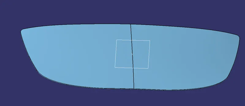
- For that we create a datum plane on the hood which will come exactly on the middle of the which we can create by taking the ratio 0.5
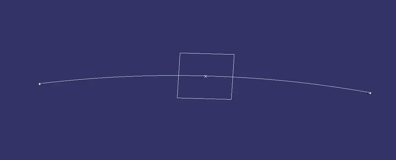
- Then create an intersection between HOOD OUTER PANEL and the plane to get intersection surface and do the same for HOOD INNER PANEL also
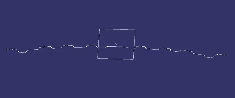
- Now we will get intersection curves,in which we have to carry out joining process by creating necessary joining lines where there will be gaps
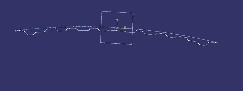
- Join the inner panel curve and the outer panel curve using trim option after creating a line in between
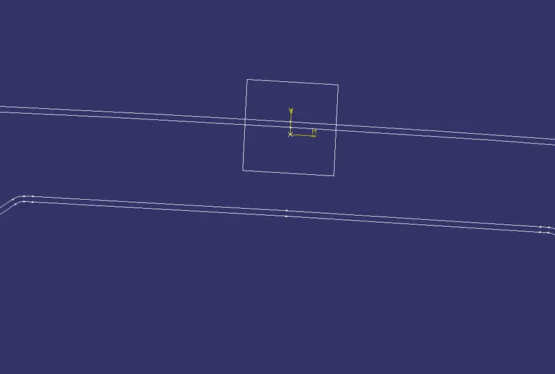
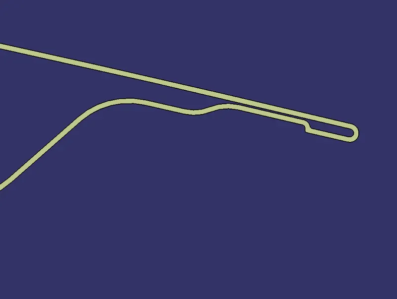
- Now offset the curve to 0.75mm inside and then use fill option to create a surface
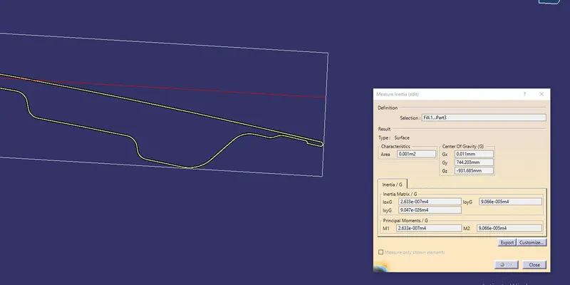
- For this surface we can measure the inertia and also the distance between outer most fibres
Calculations
Moment of inertia values
Mmin=2.633e-007 m 4
=2.633* 105 mm4
Mmax=9.066e-005 m4
=9.066* 103 mm4
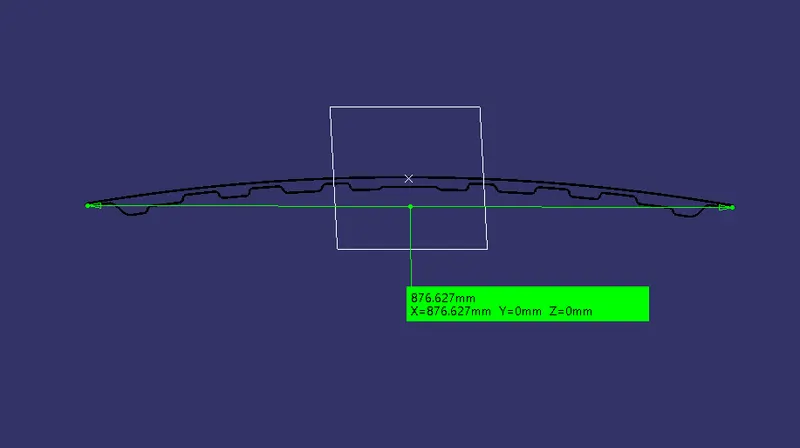
Disatnce between extreme most fibres=876.627mm
Distance between extreme most fibre to neutral most fibre=876.627
=438.3135mm
Section modulus=S=I/Y
For I,we take the min. value to calculate the secftion modulus
S=2.633* 105 mm4/438.3135mm
S =600.711mm3
Datum plane through the middle of the cross section
Intersection of the hood outer panel
Intersection of hood inner panel
Boundary created after joining by creating necessary lines
cross section created after offseting 0.75mm
Cross section created using fill operation
Moment of inertia of the cross section
Distance between the outer most fibres of the cross section
Iteration 2
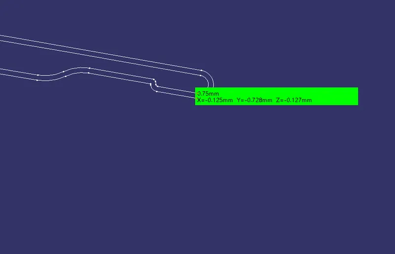
- For the iteration 2 also proceed with the same steps as in the first iteration but create the offset to 0.75mm outside of the outer boundary of the first iteration
Calculations
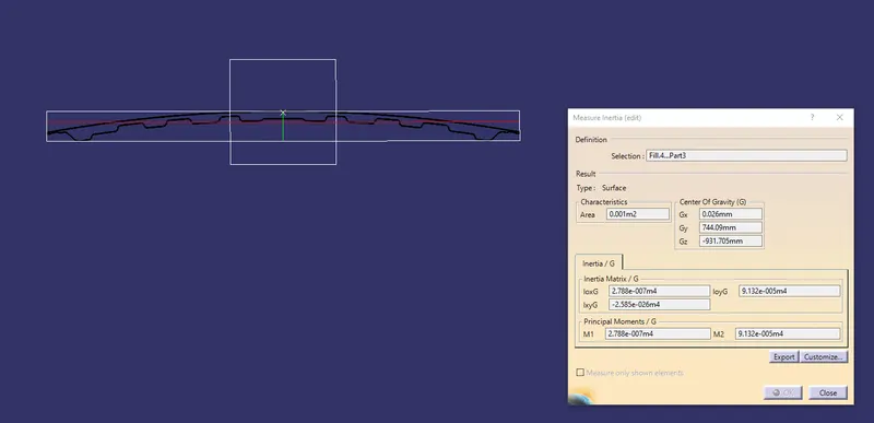
Moment of inertia values
Mmin=2.788e-007 m 4
=2.788* 105 mm4
Mmax=9.132e-005 m4
=9.132* 103 mm4
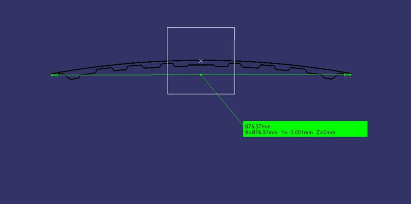
Disatnce between extreme most fibres=876.37mm
Distance between extreme most fibre to neutral most fibre=876.37
=438.185mm
Section modulus=S=I/Y
For I,we take the min. value to calculate the secftion modulus
S=2.788*105 mm4/438.185mm
S=636.260mm3
Offseted sketch
Moment of inertia of the second cross section
Distance between outer most fibres of the second cross section
CONCLUSION
- From the two iterations it is observed that the value of section modulus is increasing from a value of 600.711 to 636.260
- From this we can say that by increasing the depth of inner panel, the moment of inertia increases thus increasing the section modulus and the strength.