Section Modulus calculation and optimization
AIM
- To calculate the Section modulus for the given hood model for two iterations and analyze which will the better to be considered.
INTRODUCTION
Section Modulus
- Section Modulus is also referred to as the Polar Modulus or the Torsional Sectional Modulus. It is denoted by Zp.
- Section Modulus is the geometric property of the given cross-section of any shaft or beam structures. It is the direct measure of the strength of the shaft section or the beam section. Higher the section modulus of a structure, the more the resistive it becomes to bending.
- The second moment of area is also known as the moment of inertia of a shape. It is directly related to the area of material in the cross-section and the displacement of that area from the centroid. Once the centroid is located, the more important structural properties of the shape can be calculated. The axis that determines the centroid is also known as the neutral axis (N/A).
- The second moment of area is a measure of the 'efficiency' of a shape to resist bending caused by loading. A beam tends to change its shape when loaded. The second moment of area is a measure of a shape's resistance to change.
- In other words, Section modulus is the ratio of total moment resisted by the section to the stress in the extreme fibre.Section modulus give us idea about how much of load the given structure can take.
- If the section modulus increases the moment of resistance increases and hence its load bearing capacity.
S = I/y
where S = section modulus
I =moment of inertia of a section
y =distance from the extreme most fiber to the neutral axis.
- There are two types of section modulus. They are as follows
- Plastic Section Modulus
- Elastic Section Modulus
Plastic Section Modulus
- The plastic section modulus is used for materials where elastic yielding is acceptable and plastic behavior is assumed to be an acceptable limit. Designs generally strive to ultimately remain below the plastic limit to avoid permanent deformations, often comparing the plastic capacity against amplified forces or stresses.
- The plastic section modulus depends on the location of the plastic neutral axis (PNA). The PNA is defined as the axis that splits the cross section such that the compression force from the area in compression equals the tension force from the area in tension. So, for sections with constant yielding stress, the area above and below the PNA will be equal, but for composite sections, this is not necessarily the case.
- The plastic section modulus is the sum of the areas of the cross section on each side of the PNA (which may or may not be equal) multiplied by the distance from the local centroids of the two areas to the PNA:
- the Plastic Section Modulus can also be called the 'First moment of area'
- The plastic section modulus is used to calculate the plastic moment, Mp, or full capacity of a cross-section. The two terms are related by the yield strength of the material in question, Fy, by Mp=Fy*Z. Plastic section modulus and elastic section modulus are related by a shape factor which can be denoted by 'k', used for an indication of capacity beyond elastic limit of material.
Elastic Section Modulus
- For general design, the elastic section modulus is used, applying up to the yield point for most metals and other common materials.
- The elastic section modulus is defined as S = I / y, where I is the second moment of area (or area moment of inertia, not to be confused with moment of inertia) and y is the distance from the neutral axis to any given fibre. It is often reported using y = c, where c is the distance from the neutral axis to the most extreme fibre, as seen in the table below. It is also often used to determine the yield moment (My) such that My = S × σy, where σy is the yield strength of the material.
PROCEDURE
Iteration - 1
- First, create a datum plane on the center curve on the hood with ratio of 0.5.
- Then, select the intersect option and the outer hood surface. After that, select the intersect option and the hood inner panel surface.
- After that close those gaps in the inner hood surface with the spline optionand finally join all the hood inner lines.
- Then, create a line from outer intersected line to the inner line so that it crosse it. After that trim that line so that the sketch is all joined.
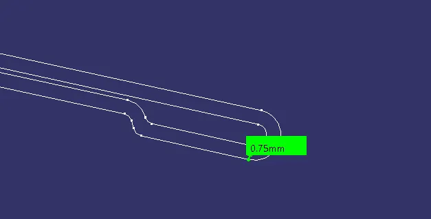
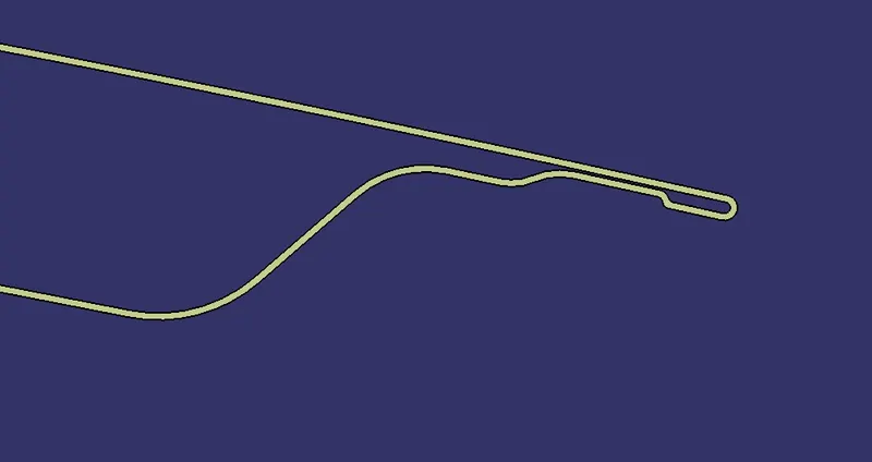
- Now, offset that sketch to the distance of 0.75 mm inwards the original sketch. Use fill option to the two closed sketches.
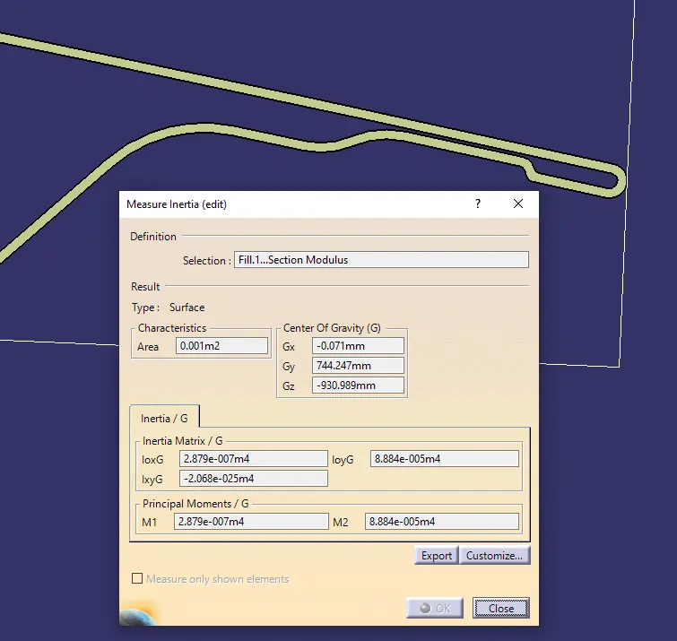
- Measure the inertia using measure inertia option in the mesaure toolbar.
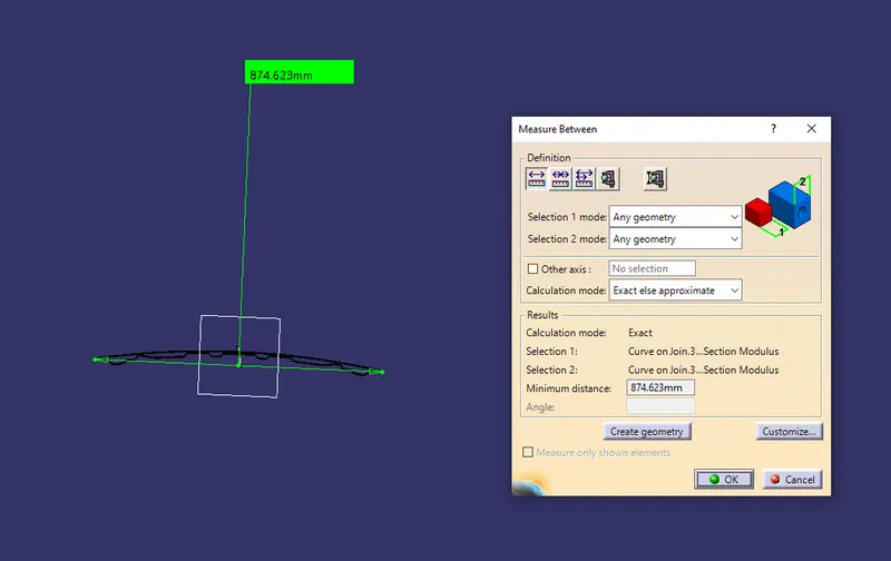
- After that mesaure the distance between the two extreme end of the surafce to get the "y" value.
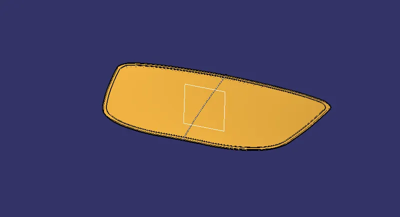
Hood Outer Panel Intersection
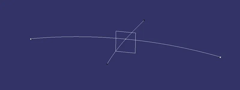
Hood Inner Panel Intersection
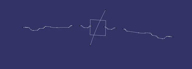
After using spline on hood inner panel intersection
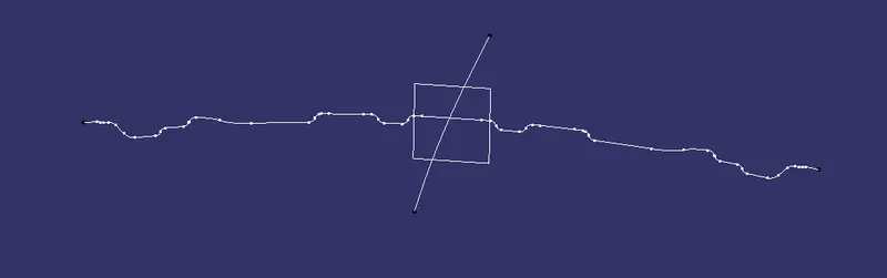
Offsetted sketch of 0.75 mm inwards
After using Fill option
Moment of inertia on Fill 1
Distance between the two extreme ends.
Calculations
Data obtained from the first iteration are
Moment of inertia values,
Mmin = 2.879e-007 m 4
= 2.879 * 105 mm4
Mmax = 8.884e-005 m4
= 8.884 * 103 mm 4
Distance from the extereme fiber to the neutral axis,
y = 874.623 mm = 874.623 / 2
= 437.3115 mm
Formula for calculating the section mdulus, S = I / y
S1 = 2.879 * 105 mm4 / 437.3115 mm
S1 = 658.340 mm3
Iteration - 2
- Same way create the sketches as mentioned in the iteration 1. Here the offseted sketch should have a distance of 0.75 mm outside the original sktech.
Sketch 1 after joining the both intersected lines.
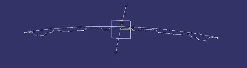
Offsetted sketch of 0.75 away from the original sketch
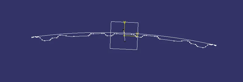
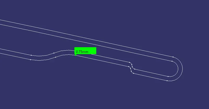
After using Fill option
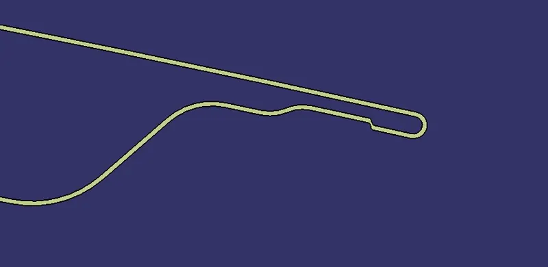
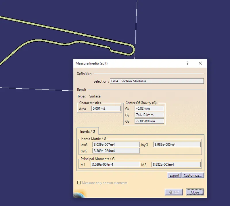
Moment of inertia on Fill 2
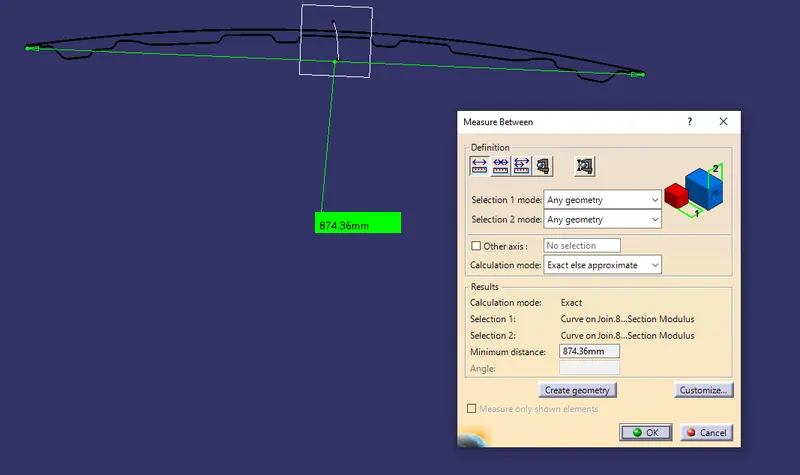
Distance between the two extreme ends
Calculations
Data obtained from the second iteration
Moment of inertia values,
Mmin = 3.039e-007 m 4
= 3.039 * 105 mm4
Mmax = 8.982e-005 m4
= 8.982 * 103 mm 4
Distance from the extereme fiber to the neutral axis,
y = 874.36 mm = 874.36 / 2
= 437.18 mm
Section modulus,
S2 = 3.039* 105 mm4 / 437.18 mm
S2 = 695.13 mm3
CONCLUSION
- From the two iterations we get, the value of section modulus is increased by 39.79 mm3 from 658.340 mm3 to 695.13 mm3
- From this we can say that by increasing the depth of inner panel, the moment of inertia increases, thus increasing the section modulus and the strength.