Section Modulus calculation and optimization
Aim:
In order to improve the total section modulus, the hood's section modulus must be determined.
Objective:
Apply the section from your Hood design to the formula S=I/y to determine the section modulus.
Theory:
The mathematical characteristics of structural shapes include section attributes. They are very helpful in the planning and design of structures. Be aware that these characteristics are solely dependent on the geometry of the section and have nothing to do with the material's strength. These attributes are
- the area's center (Centroid)
- Moment of Inertia (I)
- Section Modulus (S)
Although a bending beam's section modulus is often determined by its extreme tensile or compressive fibers, compression is frequently the most important case because of the beginning of flexural torsional buckling. The allowed stress or capacity of tensile extreme fibers is often higher than that of compressive fibers.
1. Area's Center (Centroid):
In structural design, the centroid of a section—which resembles the shape's center of gravity—is crucial. The centroid is evident, and many other straightforward shapes are symmetrical about the x-x and y-y axes.
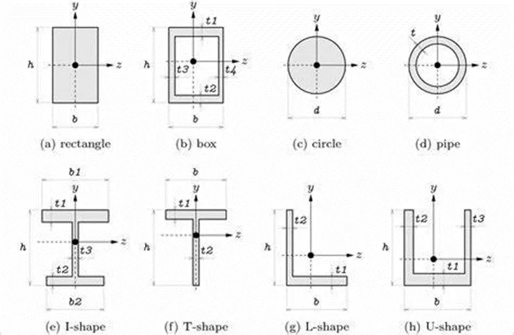
2. Moment of Inertia:
- A geometrical characteristic of an area called the second moment of the area describes how its points are distributed with respect to any given axis. In most cases, I is used to indicate the second moment of area.
- The second moment of area is frequently referred to as the shape's moment of inertia. It is closely related to the amount of material present in the cross-section and how far away from the centroid that material is located.
- The more crucial structural characteristics of the shape can be determined once the centroid has been identified. The neutral axis (N/A) is another name for the axis that determines the centroid.
- The second moment of area measures a shape's "Efficiency" to withstand bending brought on by loads. When loaded, a beam has a tendency to change shape. The resistance of a shape to change is gauged by its second moment of area.
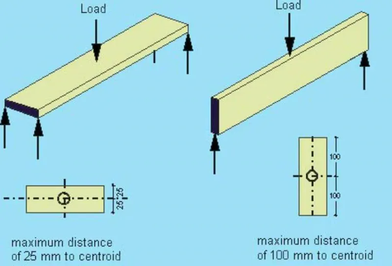
Calculating Moment of Inertia:
Simple formulas have been developed for basic shapes like squares, rectangles, and circles, and the values must be determined for each instance.
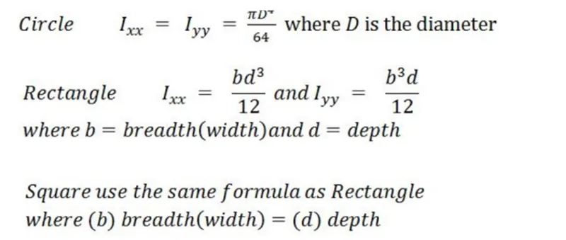
A common way to express a moment of inertia is to write the number mm^4.
3. Section Modulus:
- Designing beams and flexural members use the geometrical property of the cross-section known as the section modulus (S). It does not physically represent anything.
- When designing beams, the cross-sectional shape's section modulus is quite important. It provides a precise indication of the beam's strength. A beam will be stronger and able to bear heavier loads if it has a higher section modulus than another beam.
- The section modulus has the symbol S. Finding the distance (y) to the outer fibers from the centroid (or neutral axis) is necessary to determine S since there is where the greatest stress could lead to failure.
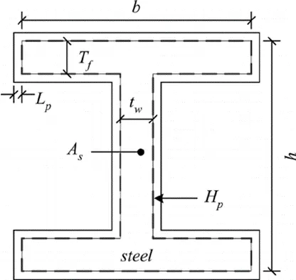
Modulus formula for the section:
- It can be described as the proportion of the section's overall moment resistance to the extreme fiber stress, which is equal to the yield stress.
- It is equivalent to yield stress.
Therefore
S=I/y, Where
- S = Section Modulus (mm^3)
- I = section's moment of inertia relative to the stress at the object's extreme end (mm^4).
- Y = separation between the object's extreme end and neutral axis (mm).
- For a symmetrical section, the value of S is the same above or below the centroid.
- For asymmetrical sections, two values are found S max and S min.
Types of section modulus:
- Elastic section modulus(S).
- Plastic section modulus(Z).
1. Elastic section modulus (S):
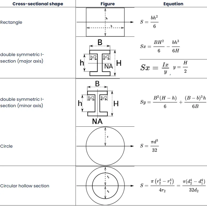
The elastic section modulus is utilized in general design and applies to most metals and other common materials up to the yield point.
S = I/y is the formula for the elastic section modulus,
where I is the second moment of area (also known as the area moment of inertia, not to be confused with the moment of inertia) and y is the separation between any two fibers from the neutral axis.
As seen in the table below, it is frequently expressed as y = c, where c is the separation between the neutral axis and the furthest fiber.
It is frequently used to calculate the yield moment (My), where My = S X σy, where σy is the material's yield strength.
2. Plastic section modulus(Z):
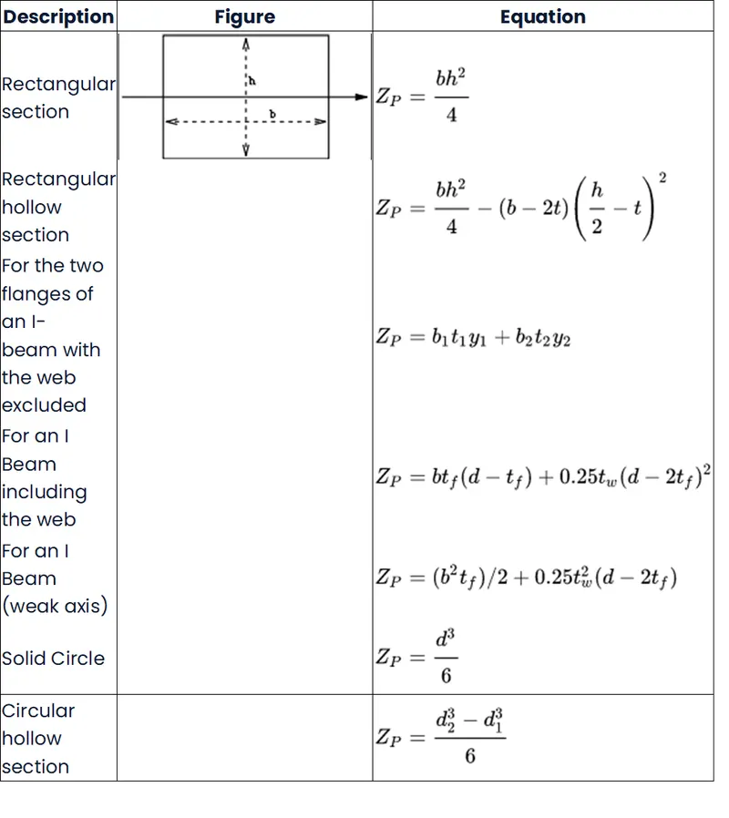
For materials where elastic yielding is permitted and plastic behavior is assumed to be an acceptable limit, the plastic section modulus is utilized. Designs frequently compare the plastic capacity against amplified forces or stresses in an effort to finally stay below the plastic limit and prevent permanent deformations.
The position of the plastic neutral axis affects the plastic section modulus (PNA). The axis that divides the cross-section so that the tension force from the area in tension equals the compression force from the region in compression is known as the PNA.
Therefore, the area above and below the PNA will be equal for sections with constant yielding stress, but this is not always the case for composite sections.
The total area of the cross-section on either side of the PNA, which may or may not be equal, multiplied by the separation between the local centroids of the two areas from the PNA, is the plastic section modulus: Acyc + Atyt = Zp
Let us consider a beam,
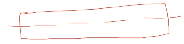
Whenever we analyze the beam, the first thing we take as a Bending moment eq.
Neutral Axis:
When a beam is bent completely, the topmost fibers are compressed to their maximum, whilst the bottommost fibers are tensioned to their maximum.
So, the Bending Moment Equation is
M/I = σb/y = E/R
According to the above bending moment equation,
- My/I = σb
- M/(I/y) = σb
- So, (I/y) = Section modulus.
Usually the section modulus we denote as Zs but in this course, we are taking it as S.
M/S = σb.
If it increases the section modulus, the σb will decrease because it's inversely proportional.
So, based on the above-derived equation I can reduce the stress by changing the shape of the material or geometry of the material.
That's why we are going to study them in a different manner in the Hood design like considering Case 1 & Case 2.
CASE 1: Before Optimization
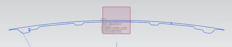
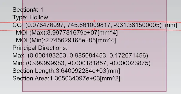
The below values are the inputs which we going to distribute the section modulus equation and the values are taken out from Hood design section inertia.
- MOI (Max) Imax = 8.997781679e+07 mm^4
- MOI (Max) Imin = 2.745629168e+05 mm^4
Distance between end to end or overall length = 879.5846 mm
So at the neutral axis, we need y value: Y/2 i.e.
- Y = Overall distance/2 = 879.5846/2 = 439.7923 mm.

As per the section modulus equation, S= I/y.
Here, we need to take the MOI (Min) i.e. Imin = 2.745629168e+05 mm^4
Therefore, S = 2.745629168e+05 mm^4 / 439.7923 mm.
S = 624.3014 mm^3.
After Optimization:
This optimization I've done for the 2 methods is increasing the thickness and the other one is adding some embossing features.
CASE 2.1: Adding(offset) 0.5mm on the bottom side. in the Inner panel side and the following results are,
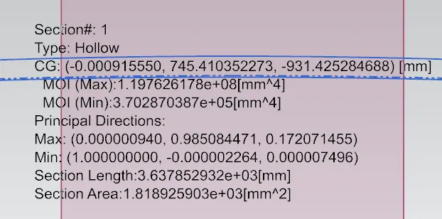
The below values are the inputs which we going to distribute the section modulus equation and the values are taken out from Hood design section inertia.
- MOI (Max) Imax = 1.197626178e+08 mm^4
- MOI (Max) Imin = 3.702870387e+05 mm^4
Distance between end to end or overall length = 879.5846 mm
So at the neutral axis, we need y value: Y/2 i.e.
- Y = Overall distance/2 = 879.5846/2 = 439.7923 mm.
As per the section modulus equation, S= I/y.
Here, we need to take the MOI (Min) i.e. Imin = 3.702870387e+05 mm^4
Therefore, S = 3.702870387e+05 mm^4 / 439.7923 mm.
S = 841.9589 mm^3.
CASE 2.2: Creating fake emboss in the center position and calculating the section modulus by comparing the results.

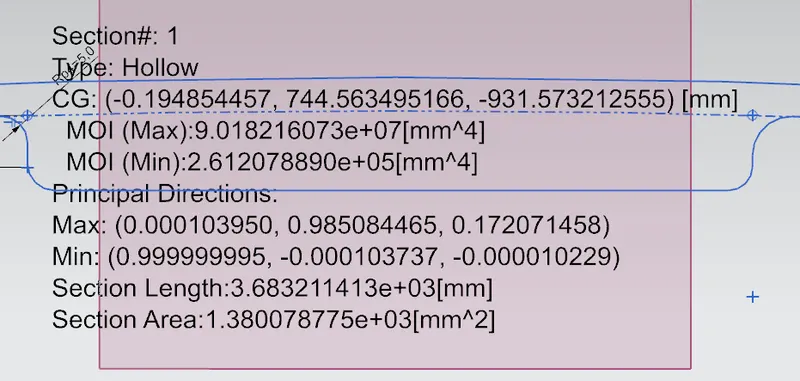
The below values are the inputs which we going to distribute the section modulus equation and the values are taken out from Hood design section inertia.
- MOI (Max) Imax = 9.018216073e+07 mm^4
- MOI (Max) Imin = 2.612078890e+05 mm^4
Distance between end to end or overall length = 879.5846 mm
So at the neutral axis, we need y value: Y/2 i.e.
- Y = Overall distance/2 = 879.5846/2 = 439.7923 mm.
As per the section modulus equation, S= I/y.
Here, we need to take the MOI (Min) i.e. Imin = 2.612078890e+05 mm^4
Therefore, S = 2.612078890e+05 mm^4 / 439.7923 mm.
S = 593.9347 mm^3.
CONCLUSION:
As a result, we created the section for the hood, estimated the section modulus, and successfully optimized the section modulus.
- Case 2's section modulus value is greater than Case 1's.
- The moment of inertia and section modulus increase as the section area is increased, increasing the material's strength and load-bearing capability.