Fender Design - Wheel Arch Challenge
FENDER WHEEL ARCH CHALLENGE
Aim:
To determine whether the front fender design will meet European requirements by calculating the fender wheel arch area and examining its criteria.
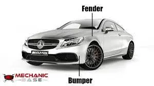
Description:
a. Fender:
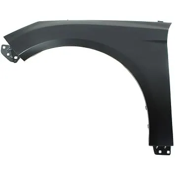
- The component of a car, motorbike, or other vehicle body that frames a wheel nicely is known by the American English name "fender" (the fender underside).
- Its main objective is to stop the revolving tire from launching debris including sand, dirt, gravel, liquids, and other road sprays into the air.
- When driving, the tires take up objects like stones and fling them around. Fenders are primarily used to limit the mobility of these particles and prevent damage to pedestrians.
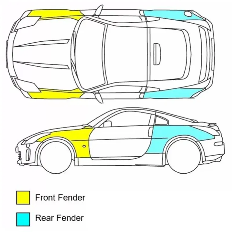
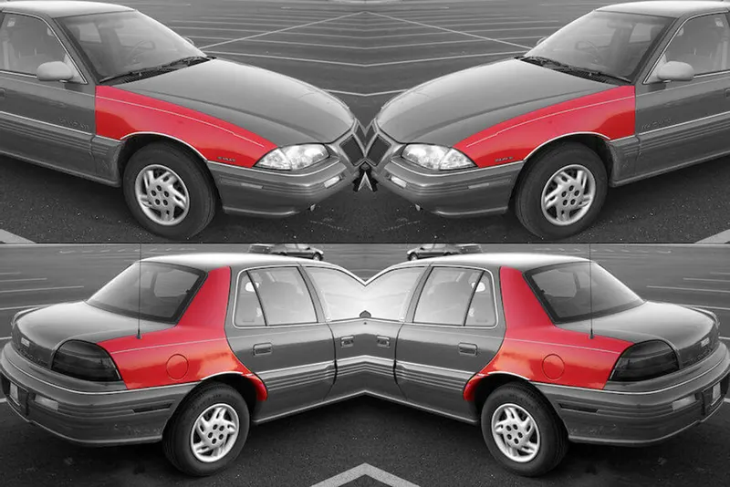
In cars, there are two different fenders kinds. It's them,
- Full bumper type and
- Half bumper type.
Full Bumper
The fender completely encloses the wheel region from the front to the body side in a full bumper style. In the beginning, OEMs and the automotive industry employed this type extensively.
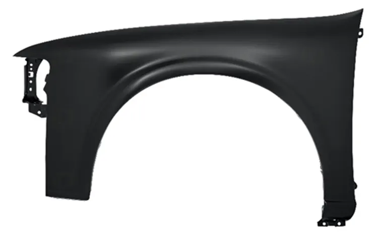
Half Bumper
When using a half bumper, the fender only covers the area of the wheel that extends from the bodyside to the front by one-third. This is due to lower material waste and production costs compared to full bumper types. These days, OEMs and the automobile industry frequently employ this type.
b. Fender wheel arch:
The fender wheel arch area is referred to as the space above the wheel and the edge separating the fender from its bottom.
As the tire rolls over the ground, sticky substances like mud may stick to the smooth outside tire surface, while smooth, loose things like stones may momentarily become embedded in the tread grooves. Given that the attached particles get kinetic energy from the tire, these materials can be ejected off the tire's surface at a high rate of speed. The top of a tire on a moving vehicle rotates upward and forward and has the potential to launch things at oncoming traffic or pedestrians. To prevent this, OEMs adhere to certain criteria for protecting pedestrians in the area where the vehicle will be driven (such as a nation or region).
These criteria are based on observational data that takes into account variables like the state of the roads, traffic, the average speed of the moving traffic, etc.
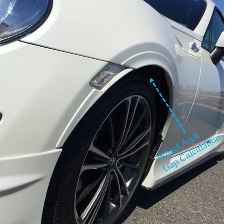
According to the vehicle's wheel clearance, suspension clearance, and turning radius clearance under stationary and moving situations, the fender wheel arch area is determined.
For fender wheel arch design, there are three regulations. It's them,
- Japan regulation standard
- European regulation standards and
- U.S regulation standard.
Japan regulation standard
In all three settings, the distance between the wheel and the fender wheel arch must be greater than 5mm (A, B & C which is shown in the following picture).
Wheel guard requirement: The value of "a" along a line 30 degrees forward and 50 degrees back from the central vertical axis of the wheel shall be more than 5mm.
To verify, create the clearance check chart in accordance with the specifications of the Japanese regulation standard and measure the clearance L of the tire, hub, cap, and fender in three separate points within area K.
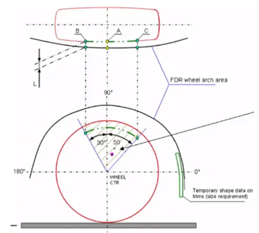
The above Sections that are indicated comply with the Japanese regulation norm.
European Regulation standard
To comply with European rules, the distance between the wheel and the fender wheel arch in sections SA-SA, SB-SB, SC-SC, SD-SD, and SE-SE must be greater than 10mm.
Wheel guard requirement: The value of "a" along a line 30 degrees forward and 50 degrees back from the central vertical axis of the wheel shall be more than 5mm.
As indicated in the accompanying image, in order to validate, measure the clearance L at sections SA-SA, SB-SB, SC-SC, SD-SD, and SE-SE. Then, create the clearance check chart in accordance with the specifications of the European regulation standard.
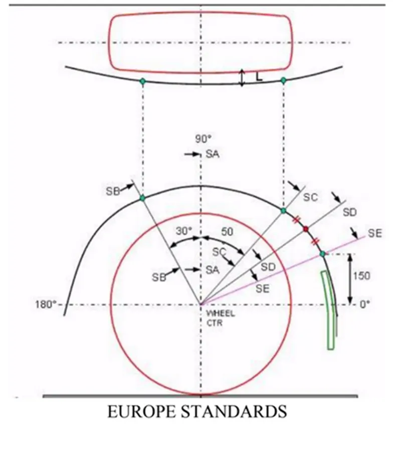
The above Sections that are indicated comply with the European regulation norm.
U.S. Standard
In any position, the distance between the wheel and the fender wheel arch must be greater than 5mm.
The value of "a" must be greater than 5mm at a line 30 degrees forward and 50 degrees back from the wheel's center vertical axis.
Measure the clearance every 10 degrees between -20 degrees and 180 degrees for validation, and then create the clearance check chart in accordance with US regulatory standards.
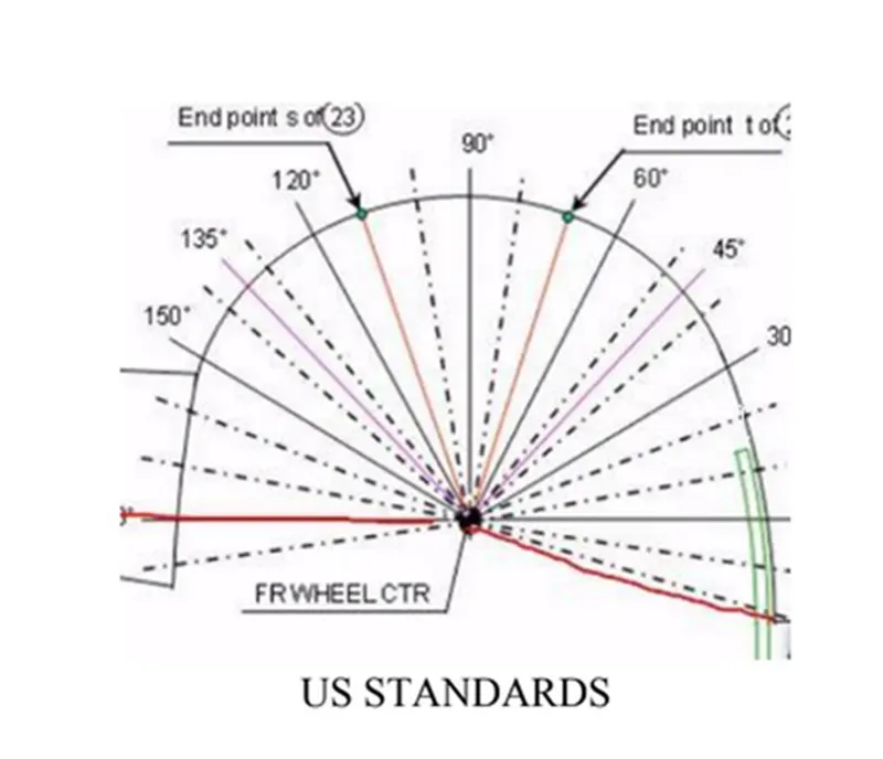
Sections taken into account by US regulation standards are displayed.
Fender wheel arch analysis Experiment:
The clearance values for the specified fender design are examined in accordance with the European regulation standard.
The specified design part file in NX is accessed in order to do the fender wheel arch analysis.
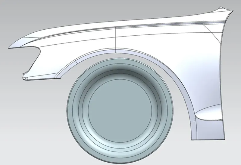
Procedure:
- We must draw a sketch on the wheel's outermost face in order to determine the clearance between the wheel arch and the wheel.
- The steps for which are described below:
- At the wheel's outermost face, a Datum Plane is formed.
- The new Datum Plane is used to produce the sketch.
- The wheel's center is divided by a horizontal line.
- The center of the wheel is dropped with a perpendicular line SA.
- At 30 degrees and 50 degrees in front of and behind SA, respectively, two lines are formed: SB and SC.
- 150 mm vertically above the center line, a point is formed.
- From the center of the wheel, a line SE is drawn that passes through the newly created point.
- In the midst of lines SC and SE, a third line, designated SD, is drawn from the center of the wheel.
Datum Plane Creation:
- Next, we take a DATUM PLANE, choose certain points and curves, then set the datum plane over a wheel curve.
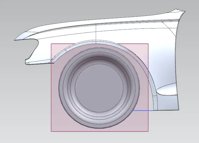
Sketch on Wheel Arc:
I started by using the horizontal line as a reference, then I drew the line using the same angles as required by European laws. I grabbed the midpoint line from the command for derived lines. I then turn the fender arc into a two-dimensional curve and identify the spots by choosing a line and a curve.
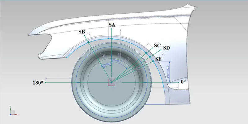
Reaching the designated 5 points with the clearing L.
Calculated at points SA-SA, SB-SB, SC-SC, SD-SD, and SE-SE, the clearance distance "L" must be larger than or equal to 10mm.
- Find the Clearance 'L' at SA-SA.
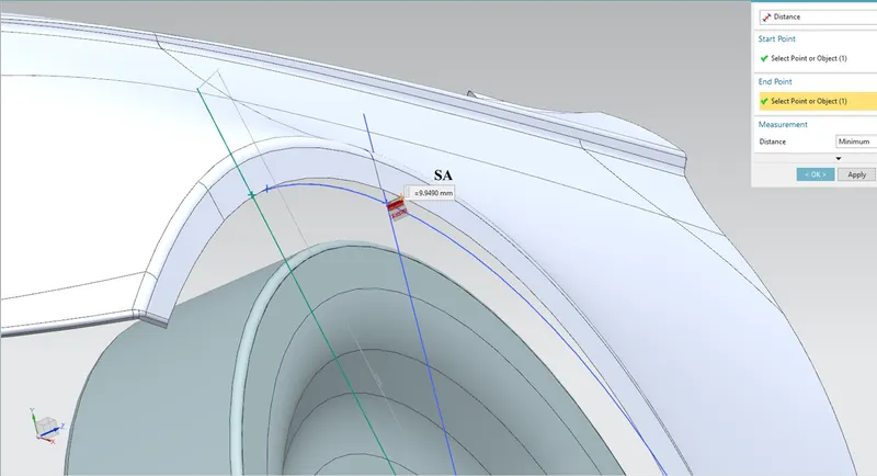
Value of L = 9.9490 mm.
- Find the Clearance 'L' at SB-SB.
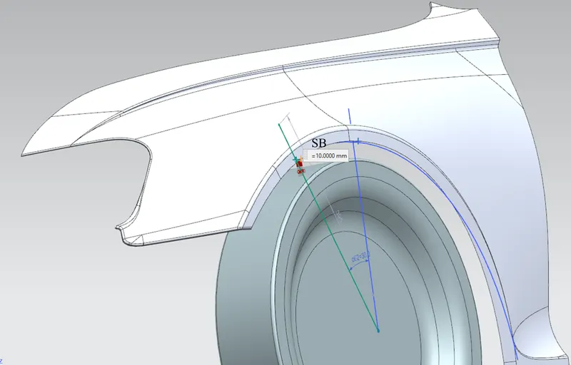
Value of L = 10 mm.
- Find the clearance 'L' at SC-SC.
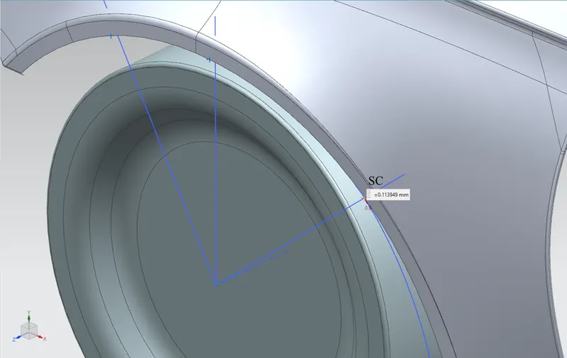
Value of L = 0.1139 mm.
- Find the Clearance 'L' at SD-SD.
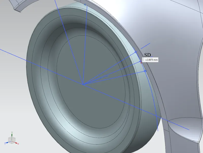
Value of L = 2.8875 mm.
- Clearance 'L' at SE-SE.
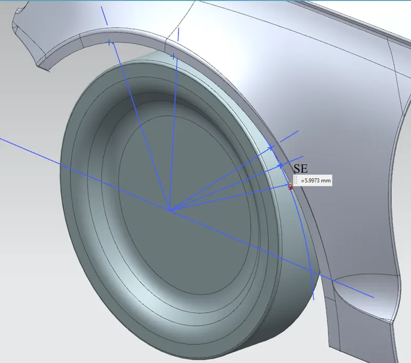
Value of L = 5.9973 mm.
Measuring the clearance value 'a' for Wheel Guard Requirement.
- Clearance 'a' at 30° line SB.
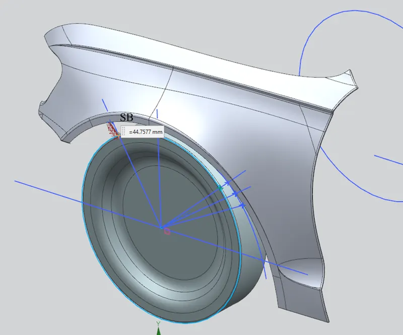
a = 44.7577 mm.
- Clearance 'a' at 50° line SC.
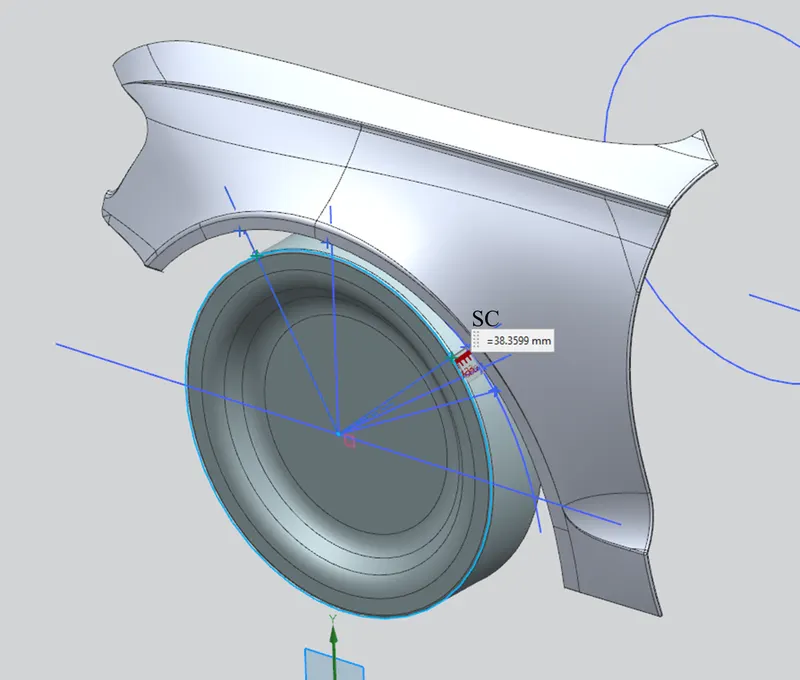
a= 38.3599 mm
Table of measurement over each area.
|
SECTION |
L(>10mm) |
Result |
a(>5mm) |
Result |
|
SA-SA |
9.9490 mm |
FAIL |
44.7577 mm |
PASS |
|
SB-SB |
10 mm |
PASS |
|
|
|
SC-SC |
0.1139 mm |
FAIL |
38.3599 mm |
PASS |
|
SD-SD |
2.8875 mm |
FAIL |
|
|
|
SE-SE |
5.9973 mm |
FAIL |
|
|
CONCLUSION:
One reason why the fender does not comply with European regulations is that its design does not provide for the required minimum horizontal space of 10 mm between the fender arch and the outermost wheel. [L(>10mm)]
However, all of the points meet the European norm for vertical clearance value. [a(>5mm)]