Fender Design
FENDER DESIGN CHALLENGE
AIM:
To use NX CAD to design the car's front fender and prepare it for manufacture by adding mounting flanges utilizing skin data (Class A surface) shared by the style team.
What is Fender:
- The component of a car, motorbike, or other vehicle body that frames a wheel nicely is known by the American English name "fender" (the fender underside).
- Its main objective is to stop the revolving tire from launching debris including sand, dirt, gravel, liquids, and other road sprays into the air.
- When driving, the tires take up objects like stones and fling them around. Fenders are primarily used to limit the mobility of these particles and prevent damage to pedestrians.
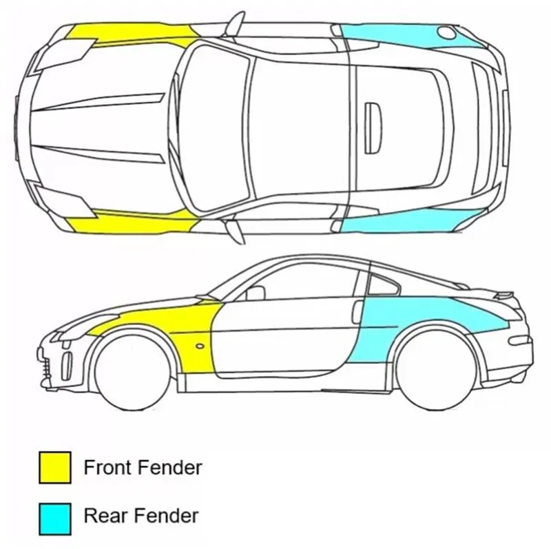
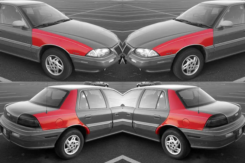
In cars, there are two different fenders kinds. It's them,
- Full bumper type and
- Half bumper type.
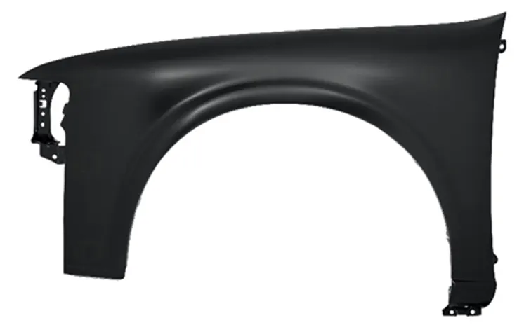
Full Bumper
The fender completely encloses the wheel region from the front to the body side in a full bumper style. In the beginning, OEMs and the automotive industry employed this type extensively.
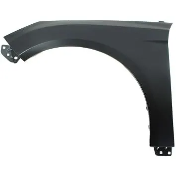
Half Bumper
When using a half bumper, the fender only covers the area of the wheel that extends from the bodyside to the front by one-third. This is due to lower material waste and production costs compared to full bumper types. These days, OEMs and the automobile industry frequently employ this type.
Importance of Fender:
- It offers protection from wind, mud, and roadside debris.
- It is the metal sheet that covers the car.
- The plastic Baffle or fender Liner that attaches to the underside of the fender prevents mud and water from entering from various road conditions, thereby protecting the metal from corrosion.
- Cleanliness: As you drive, keep the automobile, its occupants, and onlookers safe from debris such as water, dirt, snow, and ice that is thrown off the tires.
- Safety: Prevents loose, flowing objects from becoming entangled in a rolling wheel and shields pedestrians from the wheel, for example, it is preferable to be near a laterally moving fender than a rolling tire.
- Aerodynamics: Reduces drag from the exposed wheels by smoothing the car's profile. For this, some fenders have side enclosures.
- Appearance in general: Fenders make a vehicle appear nicer, more polished, and sleeker.
Designing a Front Fender:
- Given data (Input):
a. Master Section: b. Skin data:
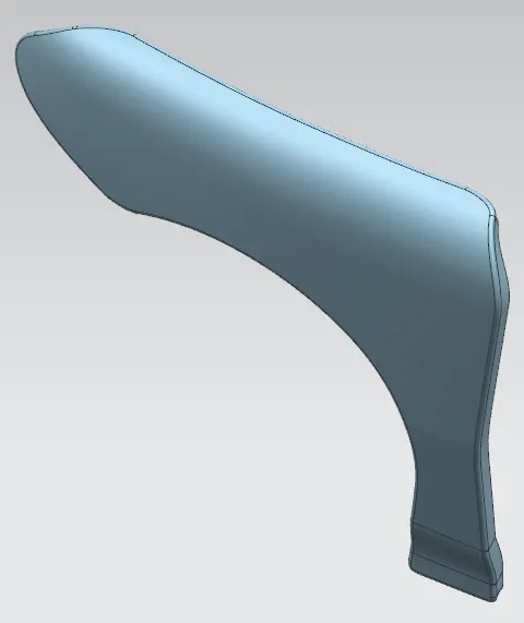
2. Design Considerations:
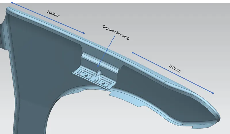
- The drip region should be constructed after leaving a space of 150 mm from the front for fixing the headlights, 200 mm from the cowl area, and 10 mm from the engine room.
- To block the view of the engine compartment, an 8mm-long, 40-degree angle from the top of the flange was built.
- The drip area's radius values at various phases.
- The fender is required to have a 0.75 mm thickness.
- Following the master section specified in the challenge itself should be used to construct the drip area mounting.
- Every other mounting should be created with design and production considerations in mind.
- Trim or blend the surface to create clean corners and edges.
- Get a smooth surface if you can.
3. Design Features Involves in this Fender design:
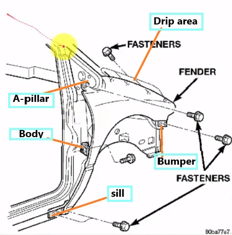
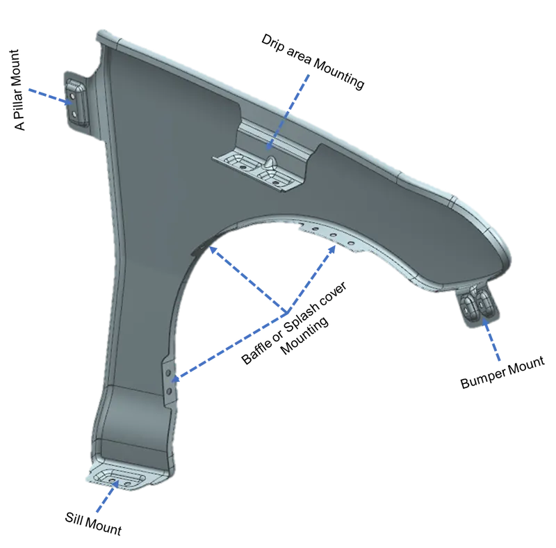
Those are the mounting portions that we need to create by using the given skin data, Keep on mind While creating those mounting features we should be considering the aesthetic, manufacturing feasibility, and assembling the components.
Mountings:
- Drip Mounting Area
- Sill Mounting Area
- A-Pillar Mounting Area
- Bumper Mounting Area
- A baffle or splash cover Mounting Area
Design Procedure step by step:
1. Drip Mounting Area
The crucial component of the fender is the attachment of the drip region. This mounting is fastened to the car's engine compartment. Weld nuts are used to attach the fender drip area to the engine compartment.
- The gap between the Hood and Fender would reveal the drip region.
- This mounting is secured to the vehicle's engine bay.
- On the front side, a minimum distance of 150mm must be maintained, and on the back, a maximum distance of 200mm must be maintained.
- To prevent spring back during production, do this. Any surrounding engine component should be at least 10mm away from the mounting's edge.
- Less than 40mm should be the drip area.
- If an emboss is made on a drip mounting, it should be flat against the curve.
- To promote stiffness, a dart is provided at the drip mounting's edge.
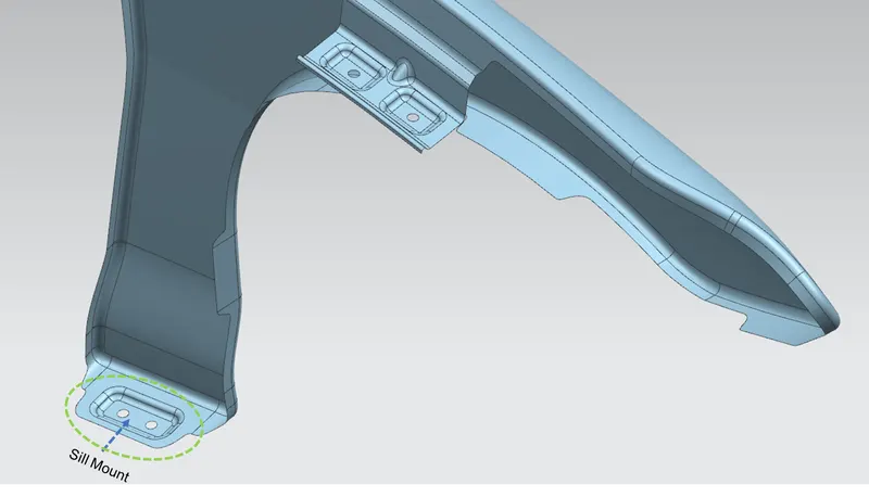
2. Sill Mounting Area:
- Basically, this is located at the bottom of the fender.
- The mounting component is made to tightly fit the sill.
- If an embosses is made on a drip mounting, it should be flat against the curve.
3. A-Pillar Mounting Area:
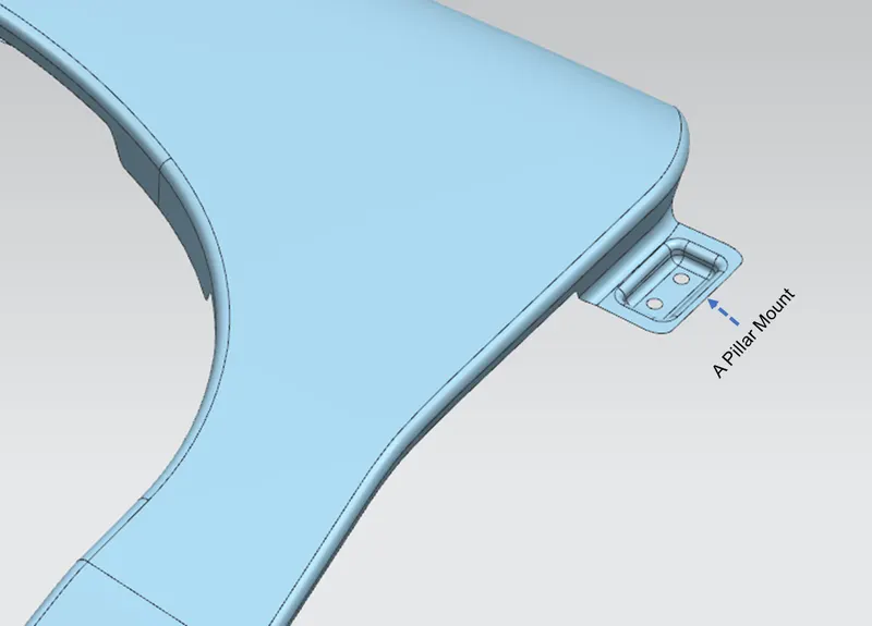
- Vertical support on a vehicle is called "A-pillar mounting."
- It keeps the windscreen in place, and the fender is fixed to hold the position directly below the A-pillar.
4. Bumper Mounting:
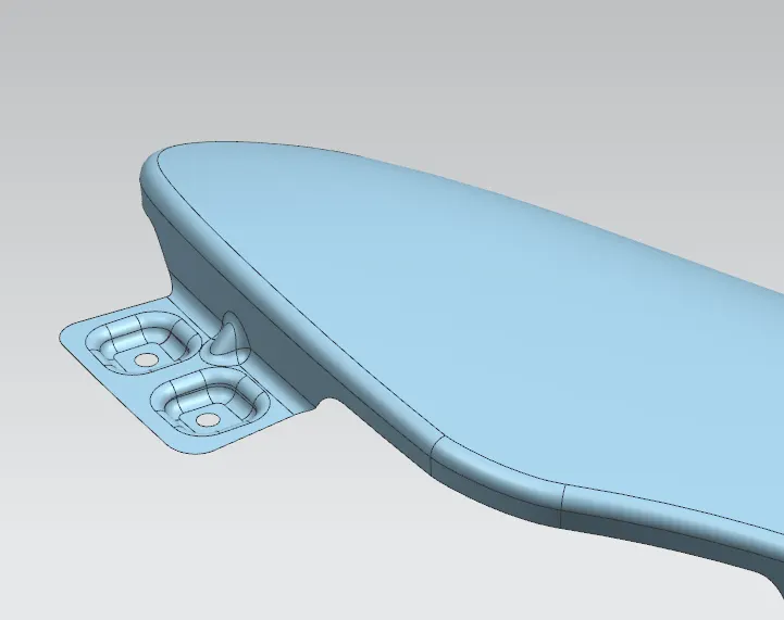
- It is positioned at the front of the fender, in the area where the bumper mounts, and it is mounted to the chassis to maintain its position.
- The area known as the "Bumper Mounting Area" is where bumpers are fastened over the fender.
5. Baffle or splash cover Mounting:
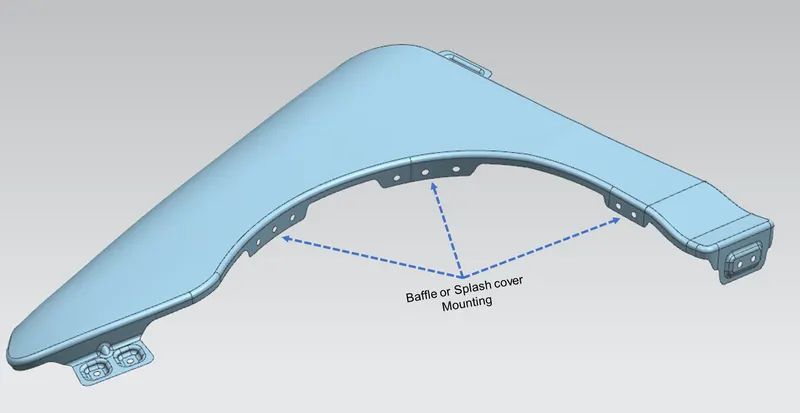
- A baffle is typically installed on the car's fender. It is fixed to the area of the wheel arches.
- A plastic component known as the baffle/splash fender linear mounting is positioned.
- The baffles/splash mounting is fixed using these mountings.
The following commands/tools were majorly used to do this fender design:
OFFSET CURVE ON FACE: The Siemens NX offset curve on face command is used to generate offset curves from connected edges or curves on the surface on one or more faces. The offset curves are located at a predetermined distance from an existing curve or edge section and might be associative or non-associative. The face is where the curves are generated, and they are measured along face portions that are parallel to the initial curves.
CURVE ON SURFACE: Siemens NX uses the curve on a surface feature to draw splines on the surface. In order to do this, we must first choose a surface and then specify the points on that surface.
BRIDGE CURVES: curves are made, shaped, and constrained using the bridge curve command in Siemens NX when connecting curves, points, surfaces, or surface edges. This command can also be used to draw symmetric bridge curves over a datum plane.
INTERSECTION CURVE: To draw intersection curves between two groups of objects in Siemens NX, use the Intersection Curve command. When two sets of faces or planes intersect, intersection curves are produced.
TRIM SHEET: In Siemens NX, you can use the trim sheet capability to cut a section of a sheet body using curves, datum planes, or faces. We can change or make a new sheet.
SKETCH: NX sketch predicts what you're going to design or draw. It pinpoints your geometric connections to the geography around you. No matter the source, NX Sketch works flawlessly with data. When you access the sheet metal domain in the NX software, this feature is in the upper-left corner of the screen.
LAW EXTENSION: Based on the laws for distance and the angle of the extension, the law extension capability in Siemens NX is used to extend an existing surface or sheet. When referencing the current face or when a specific orientation is crucial, Law Extension generates flanges or extensions. Draft direction, for instance, is crucial when designing molds or dies because it helps create separation surfaces.
FACE BLEND: In Siemens NX, you can create tangent blend faces between two or three sets of faces by using the face blend feature. The blend's cross-section can be circular, conical, or governed by regulation.
EDGE BLEND: Siemens NX's edge blend capability is used to blend two sharp faces together.
PROJECT CURVE: The Siemens NX project curve feature is used to project curves, edges, or points outside the sketch onto the sketch along the sketch's plane normal.
EMBOSS: Siemens NX's emboss function is used to produce embossed faces. To reduce the stiffness and strength of the body, use the emboss command.
DART: The Siemens NX dart feature adds a dart feature along the curve where two sets of faces connect. The vibrations and noises that are produced when the vehicle is moving are caused by the dart being utilized on the huge faces. This dart makes the long section more stable, which significantly lessens vibrations and noises.
SEW: In Siemens NX, the sew capability is used to stitch together or integrate two surfaces into a single surface. The bodies must not have any gaps that are larger than the allowed tolerance value in order to be sewn.
THICKEN: In Siemens NX, the thicken function is used to combine a number of connected faces or sheets into a single solid body. Offsetting the chosen faces along their face normals causes thickening, which is followed by the formation of sidewalls.
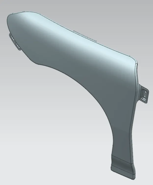
Final CAD image after Thicken:
Manufacturing Process in Metal forming to create Fender:
- Blanking and cutting
Cutting procedures involve exerting a shearing force that is sufficient to cause the material to fail in order to separate a piece of sheet metal. The technique of "blanking," used to manufacture steel, involves passing a coil of sheet metal into a press and die. The blank is then punched out of the huge metal sheet.
- Bending
Metal can be bent by exerting force, which causes it to bend at an angle and take the desired shape. This procedure frequently results in the metal taking the shape of a "V" or a "U." Applying force to a workpiece is how this is accomplished. Mechanical, pneumatic, or hydraulic forces may be applied to the workpiece.
- Embossing
Embossing Using matched male and female roller dies, theoretically with no change in metal thickness, or by passing a sheet or a strip of metal between rollers of the required pattern, embossing is a metal forming process for producing raised or sunken designs or relief in sheet material.
CONCLUSION:
NX application has been successfully used to design mountings for automotive fenders such as Bumper mounting, A-pillar mounting, sill mounting, splash cover mounting, and drip area mounting.