Section Modulus calculation and optimization
Aim:
To create the section for hood and calculate section modulus and optimization the section modulus.
Theory:
Section properties involve the mathematical properties of structural shapes. They are of great use in structural analysis and design. Note that these properties have nothing to do with the strength of the material, but are only based on the shape of the section. Those properties are
- Centre of area (Centriod)
- Second moment of area (or) Moment of inertia (I)
- Section modulus (S)
Though generally section modulus is calculated for the extreme tensile or compressive fibres in a bending beam, often compression is the most critical case due to onset of flexural torsional buckling. Generally tensile extreme fibres have a higher allowable stress or capacity than compressive fibres.
Centre of Area (Centriod):
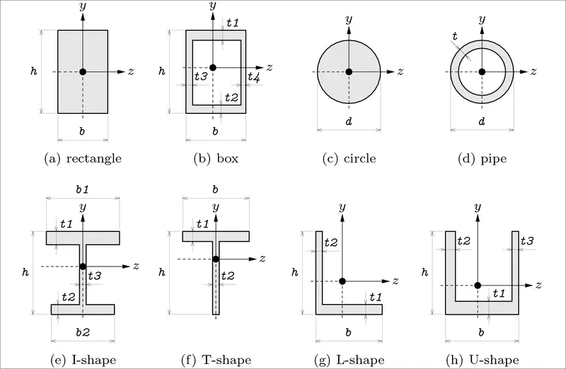
- The centriod of a section is important in structural design and is like the centre of gravity of the shape. Many other simple shapes are symmetrical about the x-x and y-y axis and the centriod can easily be seen.
Moment of Inertia (I):
- The second moment of area is a geometrical property of an area which reflects how its points are distributed with regard to an arbitrary axis. The second moment of area is typically denoted with I.
- The second moment of area is also know as the moment of inertia of a shape. It is directly related to the area of material in the cross-section and the displacement of that area from the centroid.
- Once the centroid is located, the more important structural properties of the shape can be calculated. The axis that determines the centroid is also known as the neutral axis (N/A).
- The second moment of area is a measure of the "Efficiency " of a shape to resist bending caused by loading. A beam tends to change its shape when loaded. The second moment of area is a measure of a shape's resistance to change.
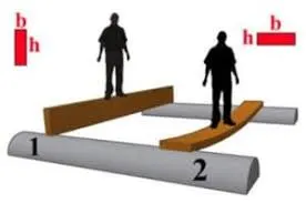
- Certain shapes are better than others at resisting bending as demonstrated in the diagram. Clearly the orientation of the shape also influences bending.
Calculating the moment of inertia (I):
- For simple shapes such as squares, rectangles and circles, simple formulas have been worked out and the values must be calculated for each case.
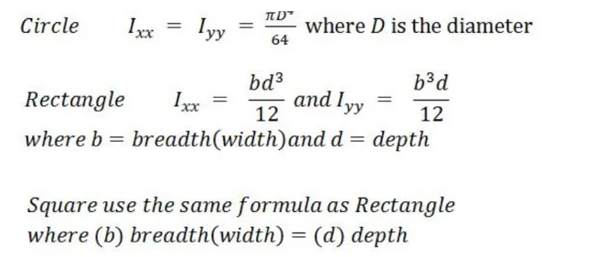
A standard method of denoting moment of inertia is to write the value mm^4.
Section modulus (S):
- The section modulus of the cross sectional shape is of significant importance in designing beams. It is a direct measure of the strength of the beam. A beam that has a larger section modulus than another will be stronger and capable of supporting greater loads.
- Section modulus is denoted by S. To calculate S, the distance (y) to the extream fibres from the centroid (or neutral axis) must be found as that is where the maximum stress could cause failure.
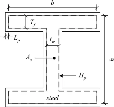
Calculating the section modulus by S = I/y
Where,
I - Moment of inertia.
y - Distance from centroid to top.
for symmetrical section the value of S is the same above or below the centroid. For a symemetrical sections, two values are found S max and S min.
Types of section modulus:
-
Elastic section modulus(S).
-
Plastic section modulus(Z).
Elastic section modulus(S):
- For general design, the elastic section modulus is used, applying up to the yield point for most metals and other common materials.
- The elastic section modulus is defined as S = I / y, where I is the second moment of area (or area moment of inertia, not to be confused with moment of inertia) and y is the distance from the neutral axis to any given fibre.
- It is often reported using y = c, where c is the distance from the neutral axis to the most extreme fibre, as seen in the table below. It is also often used to determine the yield moment (My) such that My = S × σy, where σy is the yield strength of the material.


 ,
,





Plastic section modulus(Z):
- The plastic section modulus is used for materials where elastic yielding is acceptable and plastic behavior is assumed to be an acceptable limit. Designs generally strive to ultimately remain below the plastic limit to avoid permanent deformations, often comparing the plastic capacity against amplified forces or stresses.
- The plastic section modulus depends on the location of the plastic neutral axis (PNA). The PNA is defined as the axis that splits the cross section such that the compression force from the area in compression equals the tension force from the area in tension.
- So, for sections with constant yielding stress, the area above and below the PNA will be equal, but for composite sections, this is not necessarily the case.
- The plastic section modulus is the sum of the areas of the cross section on each side of the PNA (which may or may not be equal) multiplied by the distance from the local centroids of the two areas to the PNA: Zp = Acyc + Atyt




 =width,
  =thickness,
  are the distances from the neutral axis to the centroids of the flanges respectively.



- The plastic section modulus is used to calculate the plastic moment, Mp, or full capacity of a cross-section. The two terms are related by the yield strength of the material in question, Fy, by Mp=Fy*Z.
- Plastic section modulus and Elastic section modulus are related by a shape factor which can be denoted by 'k', used for an indication of capacity beyond elastic limit of material. This could be shown mathematically with the formula .
K = (Z/S)
Shape factor for a rectangular section is 1.5.
Design and calculation :
Case 1:
- For calculating the section modulus we need to find out the moment of inertia and the y value.
- So we first open the body file of hood both inner and outer panel.
- Then we take inter section of the hood panel in the y direction using the tool intersection curve command.
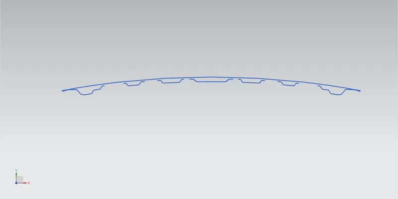
- Then we got the required curve through hood panel.
- Then we required the outer panel outer lines and for inner panel we need the outer lines.
- Then select the sketch option and by using project curve option in the sketch we get the required curve in the plane and trim the unwanted lines and curves.
- Then join the inner and outer panel in both ends as shown in figure.
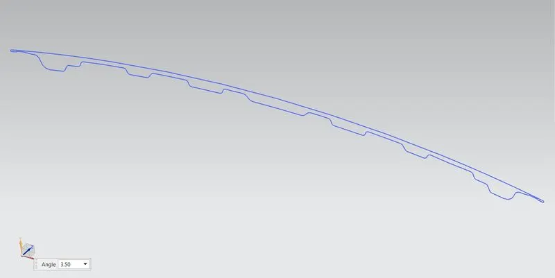
- Now we have the required cross section of the hood panel.
- Then we try to find out the moment of inertia for this curve in NX cad we use Section inertia Analysis command.
- By using this tool in the created cross section curve we can find out the inertia value.
- Open the Section inertia Analysis command and in that select object we need to select the full curve of the hood section. Then it will show the results as shown in figure.
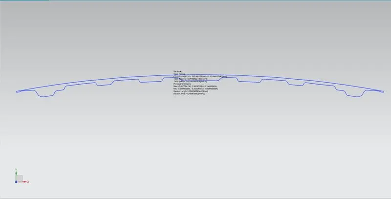
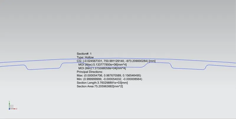
- And for find out the y value we need to find the distance from the outer most end of the cross section by using dimension obtions.Then divide the obtained value by 2 as we want the half distance.
- Here the distance is 893.89 mm as shown in figure.
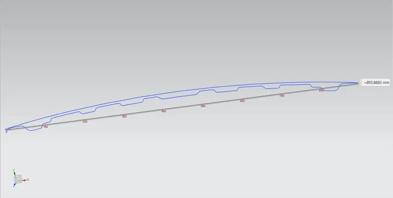
So, the total distance is 893.89 mm
The moment of inertia for this case 1 is,
MOI (max) = 5.134X10^6 mm^4
MOI (min) = 1.516X10^4 mm^4
As per the section modulus equation,
S=I/y
here,
I - MOI (min) we need to take
Y - Total distace/2 => 893.89/2 => 446.95 mm
S = (1.516X10^4) / 446.95
= 15160 / 446.95
S = 33.92 mm^3.
Case 2: (Offset by 3mm)
- For this case 2 we now increase the depth for the hood panel for inprove the section modulus.
- So, for increase depth inner hood panel curve is offset by 3mm outwards as shown in figure.
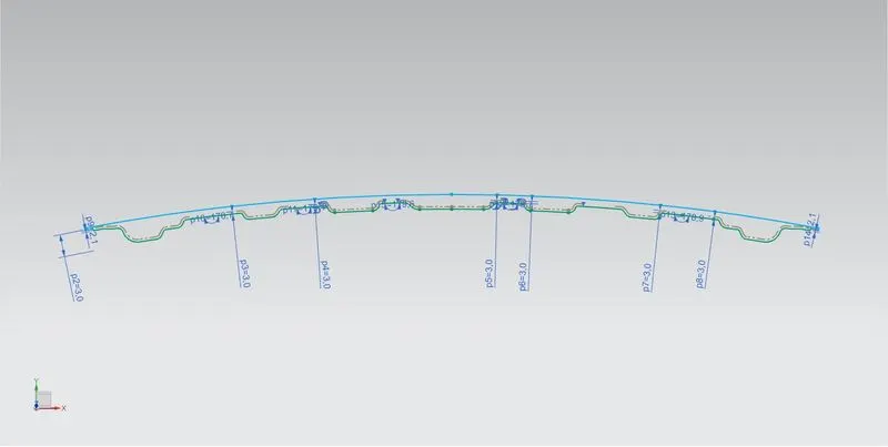
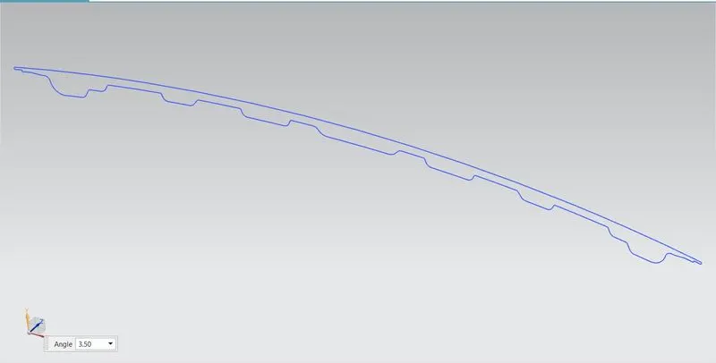
- Then section inertia analysis is done same as case 1 for a closed curve.
- By the same procedure followed in the case 1 is also followed and finally we get the results as shown in figure.
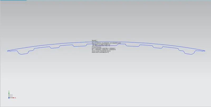
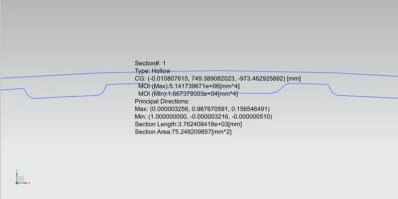
So, the total distance is 893.89 mm
The moment of inertia for this case 1 is,
MOI (max) = 5.142X10^6 mm^4
MOI (min) = 1.667X10^4 mm^4
As per the section modulus equation,
S=I/y
here,
I - MOI (min) we need to take
Y - Total distace/2 => 893.89/2 => 446.95 mm
S = (1.667X10^4) / 446.95
= 16670 / 446.95
S = 37.30 mm^3.
So, here we can see the section modulus of case 2 has increased when compared to the case 1. Thus, the Moment of inertia has been increased and the strength of the hood also increased.
Conclusion :
Hence we create the section for hood and calculated section modulus and optimization the section modulus also done sucessfully.
- The section modulus value of case 2 is higher than the case 1.
- As we increase the section area, the moment of innertia and the section modulus increases which means strength and load withstand capacity of the material can be increase.