Roof Top Crash Analysis
AIM:-
To setup & run the simulation of Roof crash- BIW of NEON and observe the errors and energy changes.
SOFTWARE:-
HYPERWORKS
OBJECTIVES:-
To locate the impactor as per given
- At 180° rotation about the global z-axis with the point opposite to C as base point.
- At 5° rotation about the axis through axis AB.
- At 25° rotation about the axis through axis AC.
- A translation to put point A at global ( -3500.00, 584.822, 1343.06).
To create an interface and setting it up.
- Create a Type 7 contact interface between the impactor and the car.
- choose an appropriate stiffness definition.
- choose an appropriate minimum gap.
- change the coefficient of friction to 0.2.
- choose the appropriate friction penalty formulation.
- Save the data from the interface to the time history file.
To create boundary condition for car.
- keep the suspension shock tower nodes locked in Z.
To create boundary condition for the impactor
- Impose the velocity of the impactor starting from 0 mm/s at t = 0.
- The displacement of the impactor should be 200 mm @ 200 ms.
- Avoid abrupt changes in the acceleration of the impactor.
To apply imposed displacement on the impactor.
- The impactor assembly contains a spring attached for stability.
- Create a BCS collector to fix the free end of the spring.
- Create a moving SKEW to define the direction normal to the impactor face.
- Create a BCS collector to guide the master node of the impactor rigid body so that it is free to translate normal to the face of the impactor, but is fixed in all other DOFs.
To create control cards.
- /ANALY card.
- /DEF_SHELL card.
- /DEF_SOLID card.
- /IOFLAG card.
- /SPMD card.
- /TITLE card.
To set up the engine card.
- Use a constant nodal time step.
- Print time history every 0.0001 seconds.
- Solve for 200 ms.
- Create an animation file every 0.005 seconds
To run the simulation.
To plot the energies graph
PROCEDURE:-
Firstly, set the user profile to RADIOSS.
Import the 0000.rad (starter file) to the graphical screen.
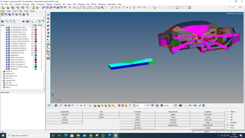
Setting the impactor
Firstly rotate the impactor by using rotate tool
Goto > Tools > Rotate.
Select the impactor elements, set angle to 180° and set the vectors to z-axis and base point as C.
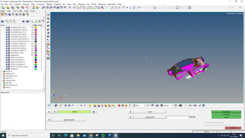
Similarly incline the impactor at 5°and 25° about x-axis using rotate.
Then move the impactor towards the car roof using translate command.
Goto > Tools > Translate or shift+F4.
Select the elements, set the magnitude to 100 and move it in global Z-axis.
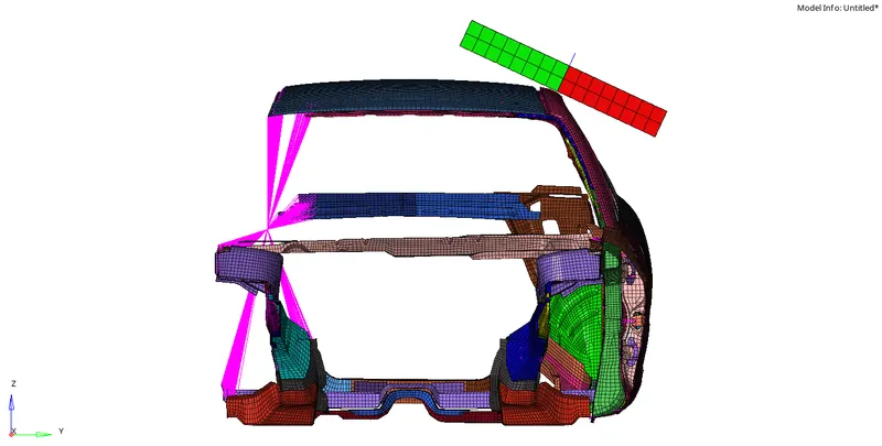
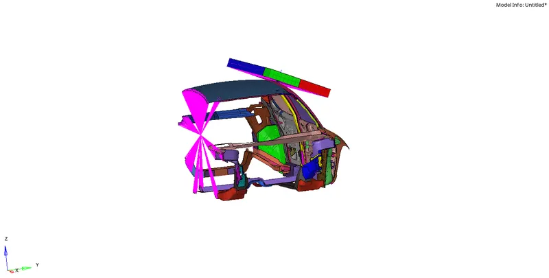
Creating an interface
To create interface type
Goto > Model bar > Right click on groups > create.
Select type 7 in the cardimage and set the parameters as below
Istf : 4 - It is the gap for stiffness definition, it is the interface stiffness which is the minimum of the master and slave stiffness.
Igap : 2 - It is the gap option flag. Igap = 2 is Variable gap + gap scale correction of the computed gap.
Idel : 2 - It is the node and segment deletion flag. When a 4-node shell, a 3-node shell or a solid element is deleted, the corresponding segment is removed from the master side of the interface. It is also removed in case of explicit deletion using Radioss Engine keyword /DEL in the Engine file.
Additionally, non-connected nodes are removed from the slave side of the interface.
Stmin : 1 - It is the minimum stiffness value which can be used only if Istf value is not equal to 1.
Irem_gap : 1 - The option Irem_gap is used to deactivate slave nodes which are close to elements. But in this case since we put the value as 1 that means there is no deactivation of slave nodes.
Stfac : 2 - Stiffness scale factor applied to the master side of the interface (if Istf is not equal to 1).
Fric : 0.2 - Coulomb friction
inacti : 6 - Deactivation flag of stiffness in case of initial penetrations. But in this case, the value is set to 6 that means the gap is variable with time but initial penetration is computed.
Gapmin : 0.5 - Minimum gap for impact activation.
Iform : 2 - Stiffness (incremental) formulation.
Similarly, another interface should be created for impactor.
In the first card select all the car nodes as master and slave and name it as Self_ impact.
In the second card select all the car nodes as slave and Impactor nodes as master and name it as Impactor_vs_car.
Now, create an output block card and name it as Interface card.
Goto > Model bar > Output block > right click on it > create.
Select the Entity_id as a group in it select Interface call.
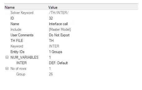
Now create boundary conditions.
Goto > View > Browser > Hypermesh > Solver.
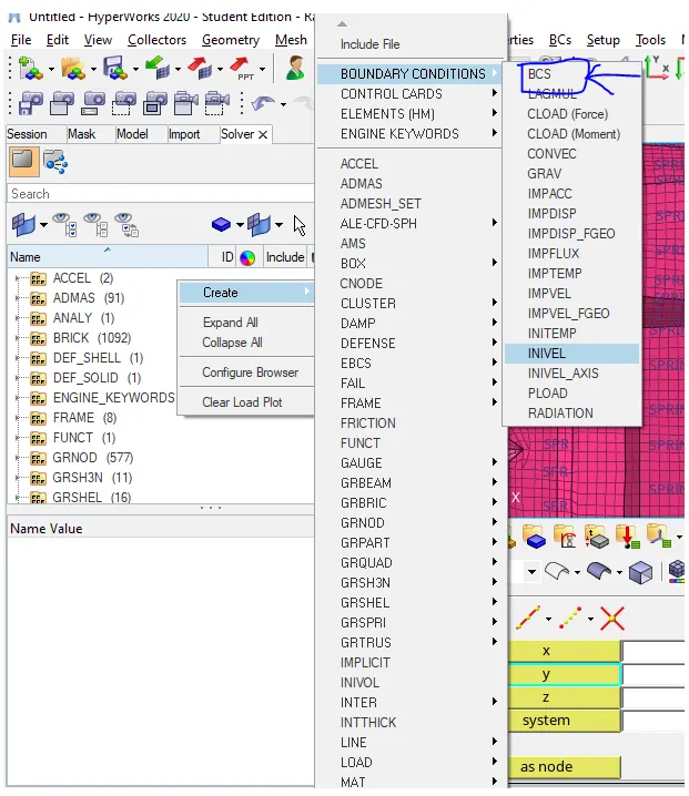
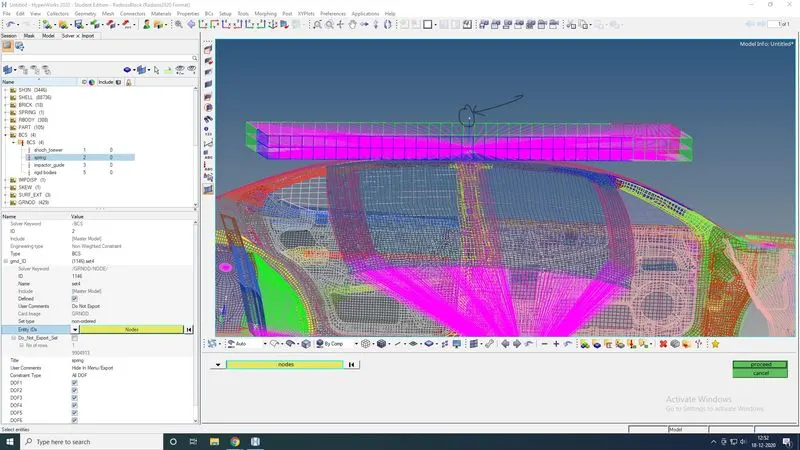
Create a BCS for suspension by right click in solver bar.
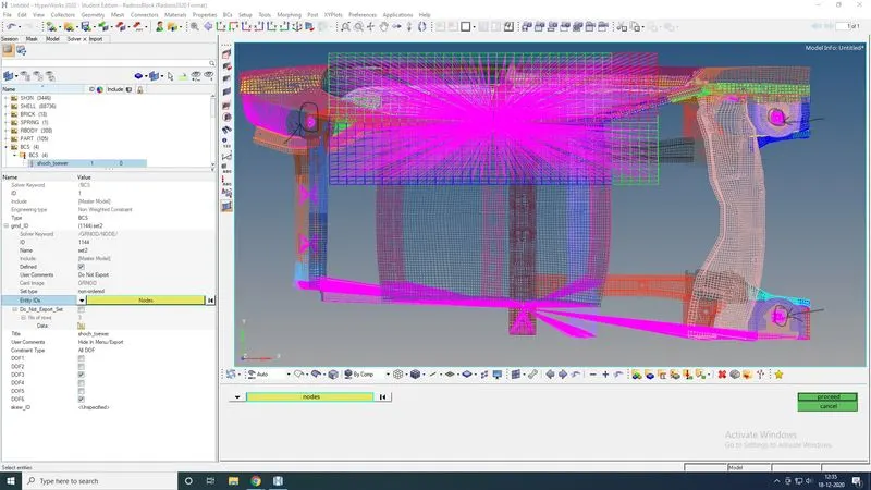
Select the grnd_ID nodes on all the three master nodes of the rigid elements and name it as Shock tower. Check DOF3 and DOF6.
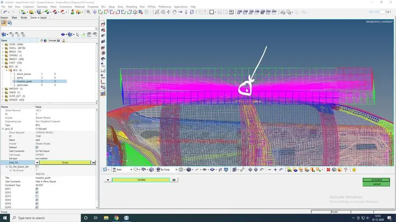
Then, create BCS for impactor by selecting the master node of rigid elements and name it as impactor_guide. DOF1, DOF2, DOF4, DOF5 and DOF6.
Then, BCS for impactor spring by selecting the node and name it as Spring.Check all DOF.
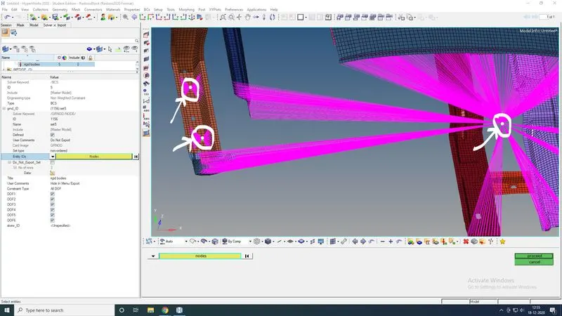
Similarly for all rigid bodies in a car by selecting the master node and name it as Rigid_body. Check all DOF.
Applying imposed displacement on impactor
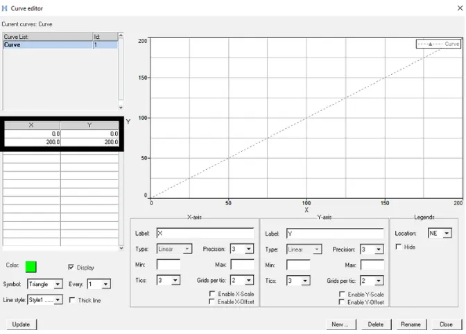
Firstly, create a curve of 0mm/ms to 200mm@200ms
Goto > Model bar > Curve > Right click > create.
Enter X,Y= 0,0 and X,Y=200,200, update and name it as IMPDISPCURVE.
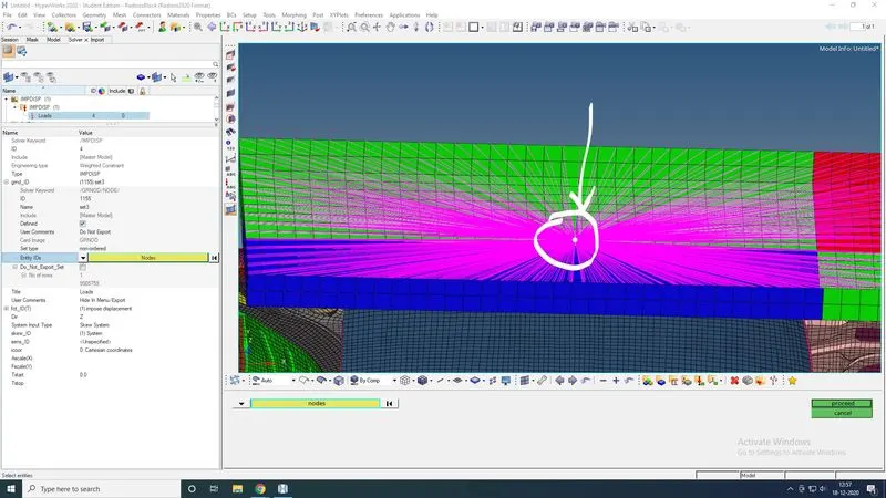
Now create imposed displacement from BCS.
Goto > Solver bar > right click > BCS > IMPDISP.
Select grnd_ID as master node of rigid element, fct_ID as IMPDISPCURVE and select skew_ID as local skew.
Now creating engine cards.
As the engine cards cannot be created without preferred values so copy the old engine file of another model and rename it.
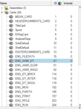
Editing Engine card.
Goto > Model bar > Cards.
Select ENG_RUN and enter Tstop=200.
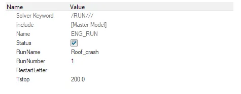
Select ENG_ANIM_DT and enter Tfreq=0.5.
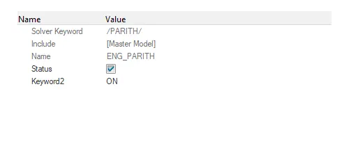
Select ENG_PARITH, Check on status and ON keyword2.
Check for penetrations and intersections.
Goto > menu bar > Tools > Penetration check.
Select the interface type 7 which we created, run to check. There are no penetrations and intersections found.
After checking penetrations and intersections
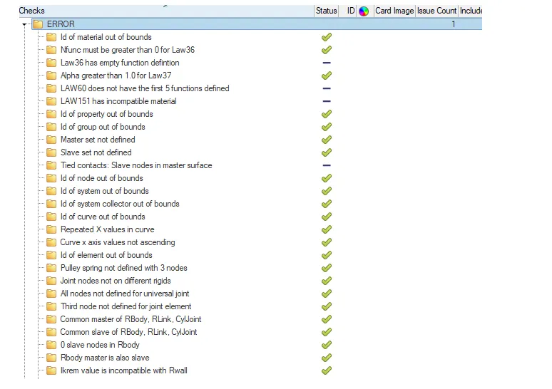
Now, Check for errors.
Goto > Tools > Model checker > RadiossBlock.
Select Error and run.

Errors which have been found after running the model checker need to be cleared. There are two methods to clear the errors.
- To export the radioss file and open in hypercrash and then delete the error that is not assigned. Then export it back to hypermesh.
Note: After the file is imported to hypermesh delete the unsupportable card.
- In hypermesh after running the model checker, Apply auto correction.
After clearing all the errors and checking the values. Run the radioss, including connectors and option value as -nt 4.
After the simulation is runned it creates .h3d,.T01,.out, starter file and engine file.
To view animate file. Open hyperview, load the .h3d file and apply.


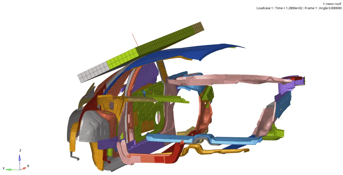
To plot graphs. Open hypergraph, load the .T01 file and apply load conditions.

OBSERVATION:-
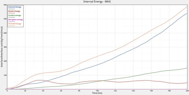
In this graph, the internal energy and total energy is parallelly increasing.
Where the hourglass energy is constant through out the graph due to no penetration and intersection.
Contact energy is increasing gradually as the impactor is forced into the roof.
Kinetic energy is varing in 0-90 kg*mm2/ms2.
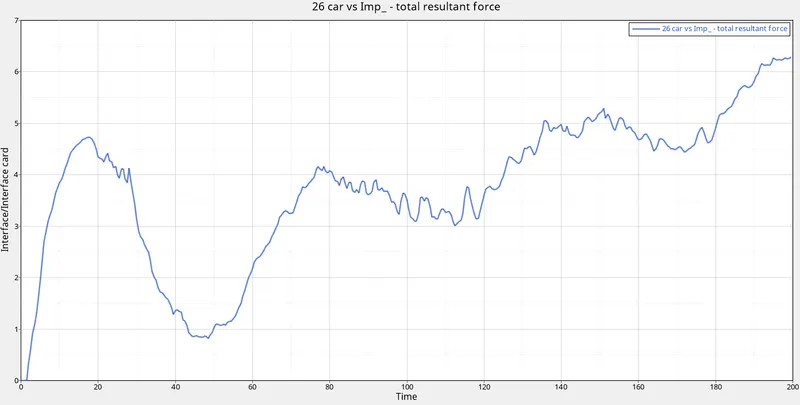
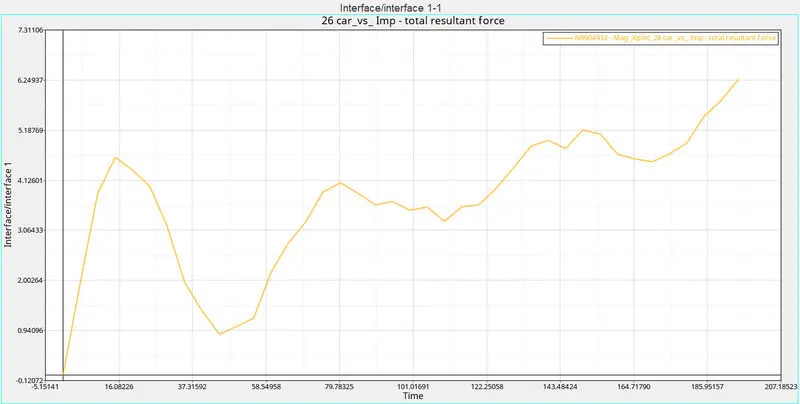
In this graph, the fluctuation gradually increasing due to force displacement. The fluctuation goes on increasing untill the force is applied.
To plot MATH CURVE
Goto > HYPERVIEW
Run the simulation, then select on build plot, select the displacement and select mag.
After that open HYPERGRAPH, split the screen.
Goto > File > Load > Preference File > Vehicle Safety Tool > LOAD.
MATH option will displayed on the screen.
Goto > MATH > Two curve > Cross plot.
A new panel bar open's, select the curve X as the mag and curve Y as IMPDISP, then apply.
Nodal mass animation
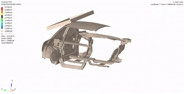
It shows that the front region near A pillar and back region C pillar node Nodal mass is acting.
Plastic-strain Animation
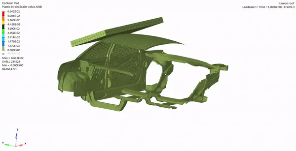
It shows the strain acting on the roof and side door region, where deformation is taking place.
Von mises Animation.
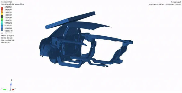
It is seen the impactor and body elements are getting effected.
Calculating Load
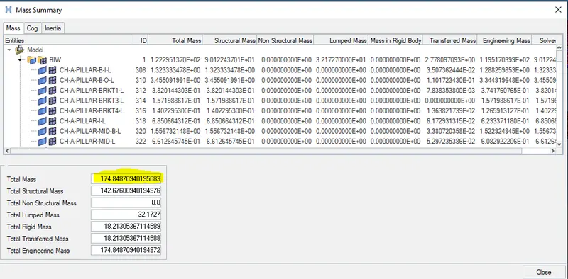
To calculate weather the COG is 3 times value equal to 47000 N.
LOAD = 3 x GVW
= 1748.4 x 3
= 5245.2 N.
Therefore, the load is more than the given FMVSS 216 value.
RESULT & CONCLUSION:-
|
CYCLE |
TIME |
TIME-STEP |
ERROR |
I-ENERGY |
K-ENERGY T |
K-ENERGY R |
MAS.ERR |
|
200000 |
200.0 |
0.1000E-02 |
-20.9% |
539.7 |
47.18 |
0.6281 |
0.4765E-01 |
The Roof crash model is setuped, simulated and runned successfully without any error.
IDIOMS USED:
GVW - It's full form is Gross Vehicle Weight which excludes seat, interior and additional parts.
Parallel Arithmetic- The result is not guaranteed in the incompatible kinematic condition. The same numerical results will be obtained whatever the number of processors.
FMVSS- Federal Motor Vehicle Safety Standard
First, for the vehicles currently subject to the standard, i.e., passenger cars and multipurpose passenger vehicles, trucks and buses with a Gross Vehicle Weight Rating (GVWR) of 2,722 kilograms (6,000 pounds) or less, the rule doubles the amount of force the vehicle’s roof structure must withstand in the specified test, from 1.5 times the vehicle’s unloaded weight to 3.0 times the vehicle’s unloaded weight.
Second, the rule extends the applicability of the standard so that it will also apply to vehicles with a GVWR greater than 2,722 kilograms (6,000 pounds), but not greater than 4,536 kilograms (10,000 pounds). The rule establishes a force requirement of 1.5 times the vehicle’s unloaded weight for these newly included vehicles.
Third, the rule requires all of the above vehicles to meet the specified force requirements in a two-sided test, instead of a single-sided test, i.e., the same vehicle must meet the force requirements when tested first on one side and then on the other side of the vehicle.
Fourth, the rule establishes a new requirement for maintenance of headroom, i.e., survival space, during testing in addition to the existing limit on the amount of roof crush. The rule also includes a number of special provisions, including ones related to leadtime, to address the needs of multi-stage manufacturers, alterers, and small volume manufacturers.
Cross plot- Cross-plot is synonym for Scatter plot to describe a specialized chart that compares multiple measurements made at a single time or location along two or more axis.