Roof Design
AUTOMOTIVE ROOF DESIGN
The car roof, an often overlooked but crucial component of an automobile, has undergone significant evolution since the inception of the automotive industry.
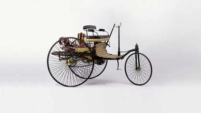
Beyond providing shelter from the elements, car roofs have played a vital role in vehicle design, safety, and functionality. In the early days of the automobile, car roofs were rudimentary, if present at all. Many of the first automobiles were open-air vehicles, exposing passengers to the whims of Mother Nature. The primary focus was on creating a functioning vehicle, and aesthetics took a back seat. As the automotive industry matured, so did the car roof.
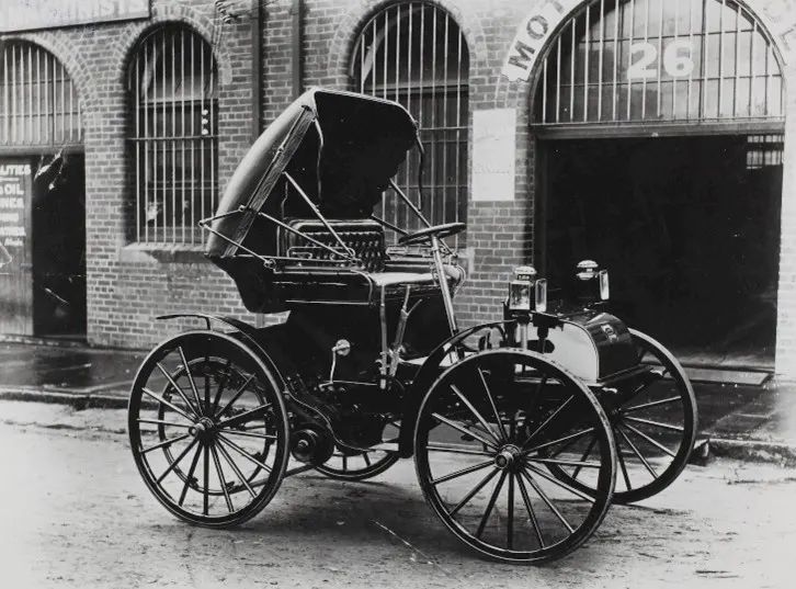
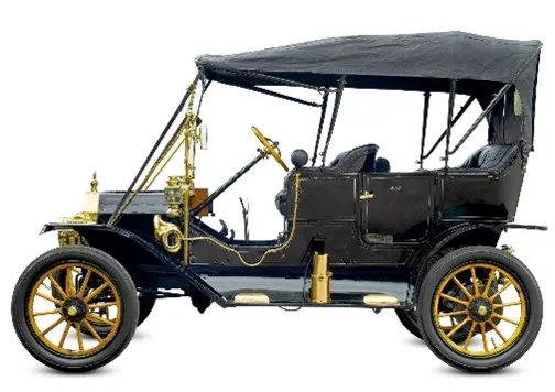
By the early 20th century, car roofs evolved to become more utilitarian, with a focus on keeping passengers dry and comfortable. Convertible roofs, often made of fabric or leather, gained popularity. These roofs could be folded down, providing the driver and passengers with the option to enjoy the fresh air or shield themselves from rain and sun. These roofs added a touch of elegance and sophistication to automobile design, making them popular among the elite.
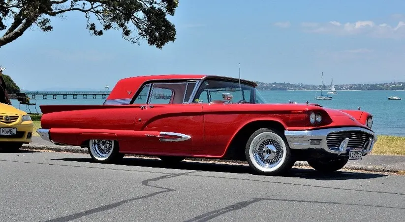
In the mid-20th century, car roofs saw a significant transformation with the advent of hardtops. These roofs were made of metal and featured a solid, fixed design. Hardtops not only improved structural rigidity but also offered a more seamless and elegant appearance. They became emblematic of the American automobile industry during the 1950s and 1960s, exemplified by the iconic Cadillac Eldorado and Ford Thunderbird.

As the focus on safety increased in the latter half of the 20th century, car roofs took on new roles. The introduction of reinforced roof pillars and safety glass improved occupant protection during rollovers. Roof designs began to prioritize crashworthiness, impacting the shape and strength of car roofs. Additionally, sunroofs and moonroofs gained popularity, allowing passengers to enjoy natural light and fresh air without compromising safety.
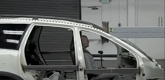
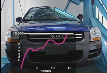
In the 21st century, car roof design has embraced a wide range of materials and technologies. Glass panoramic roofs offer expansive views, enhancing the driving experience. Solar panels integrated into car roofs are being developed to harness energy for auxiliary systems, contributing to sustainability efforts. Retractable hardtops in convertible models combine the best of both worlds, offering open-air driving when desired and a solid roof when needed.
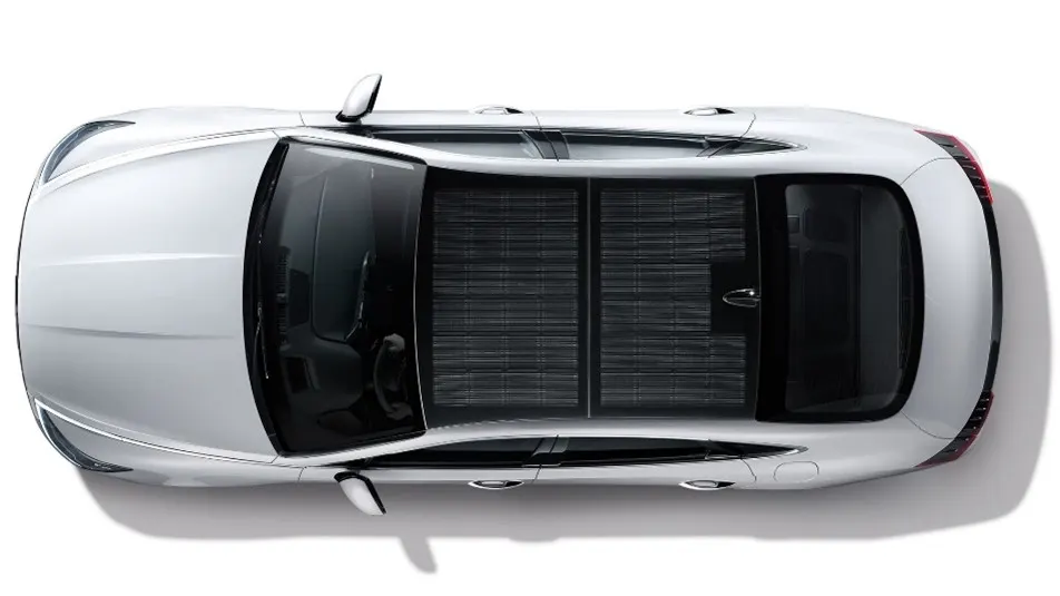

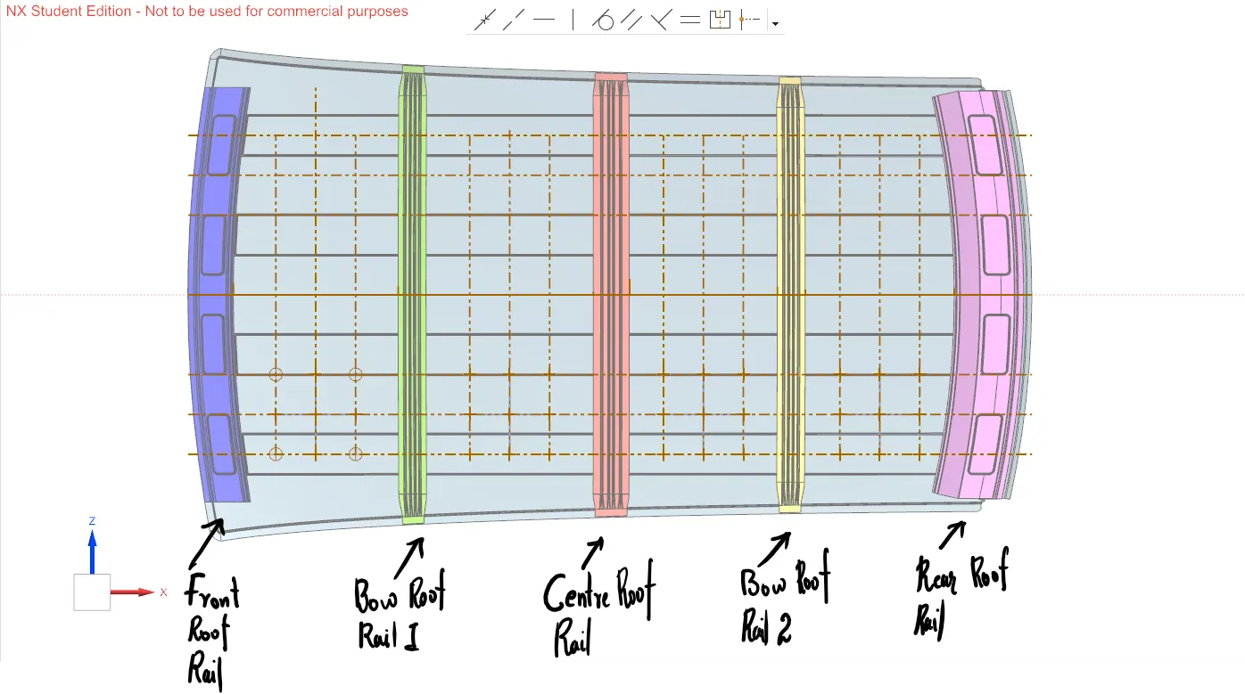
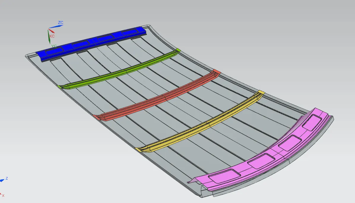
In the proceeding exercise I developed the sheet metal structure of an automotive roof with proper consideration from master section and tool opening angle of 7 degree. The class A given from the designing team is carefully analyzed for discontinuity errors and extracted surface to work on modeling. From the master section of front roof rail, bow roof rail, center roof rail and rear roof rail, the surfaces necessary for thickening was created.
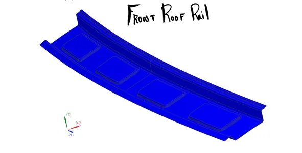
Front roof rail was designed using the surface modeling tool and tool opening angle of 7 degree was ensured. The outer panel of the roof was initially developed; 2 mm clearance for the sheet body and mastic clearance of 5 mm which is given on the master section diagrams was added to the design. While designing the front roof rail proper care should be given to reduce the impact of the roof rail on driver visibility and to increase the head room for the occupants all the while ensuring a safe roof panel which can withstand the impact test and survive a roll-over.
<!-- [if gte vml 1]>
<!--[endif]-->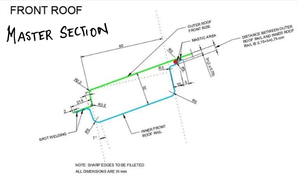
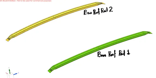
Bow roof rails were then developed using the given input from master sections. Two bow roof rails were created for the roof, one after the front roof rail and another before the rear roof rail.
<!-- [if gte vml 1]>
<!--[endif]-->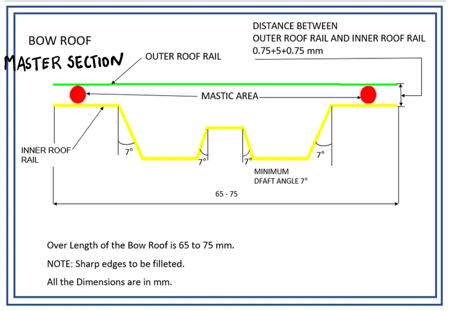
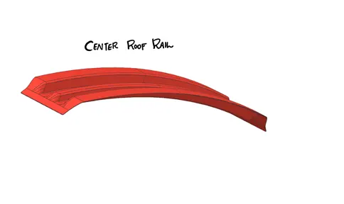
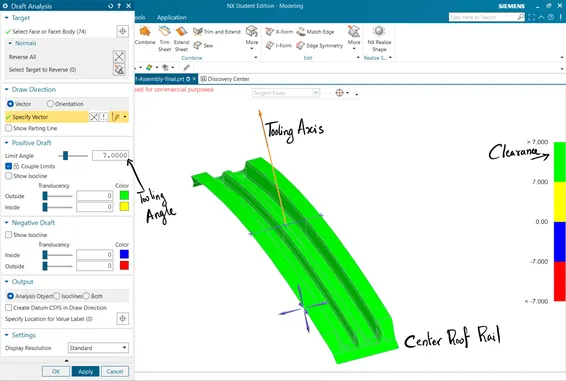
The center roof rail adds additional support and integrity to the roof panel. Reinforcement rails are must for automotive roof panels having the option to provide sunroof or moonroof. I had taken the automotive roof without sun roof consideration.
<!-- [if gte vml 1]>
<!--[endif]-->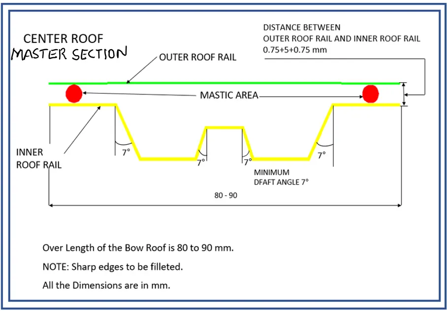
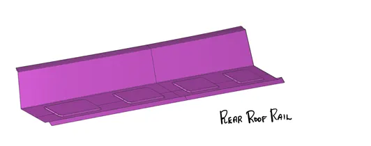
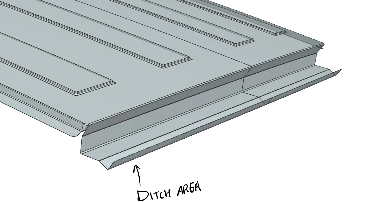
Finally, the rear roof rail too was developed according to the inputs from master section. Roof rail rear has design constraints such as the back door hinge mechanism and ditch area integration.
<!-- [if gte vml 1]>
<!--[endif]-->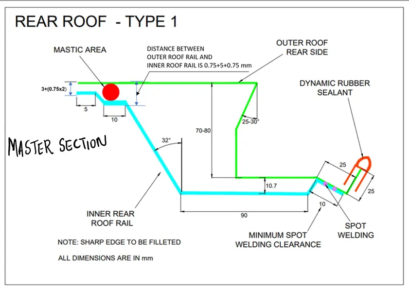
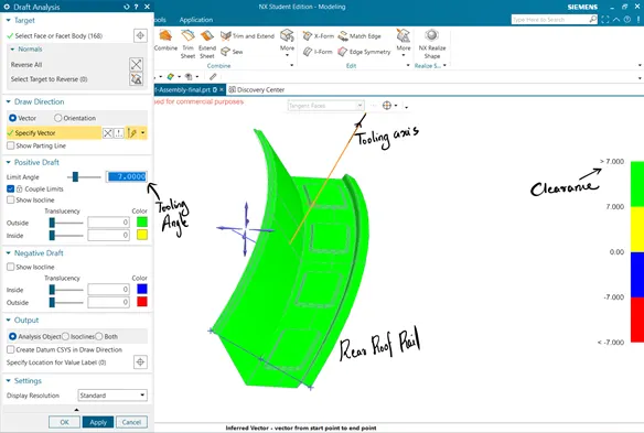
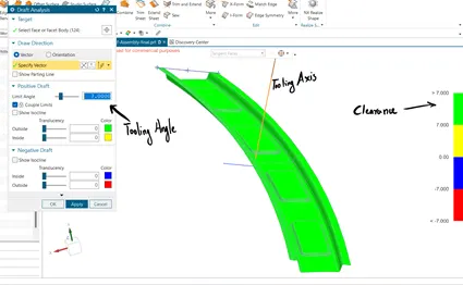
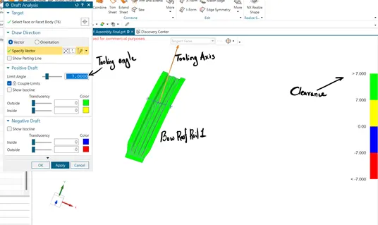
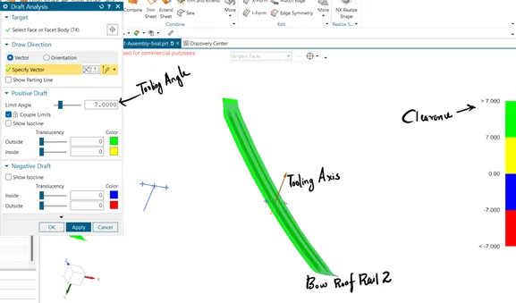
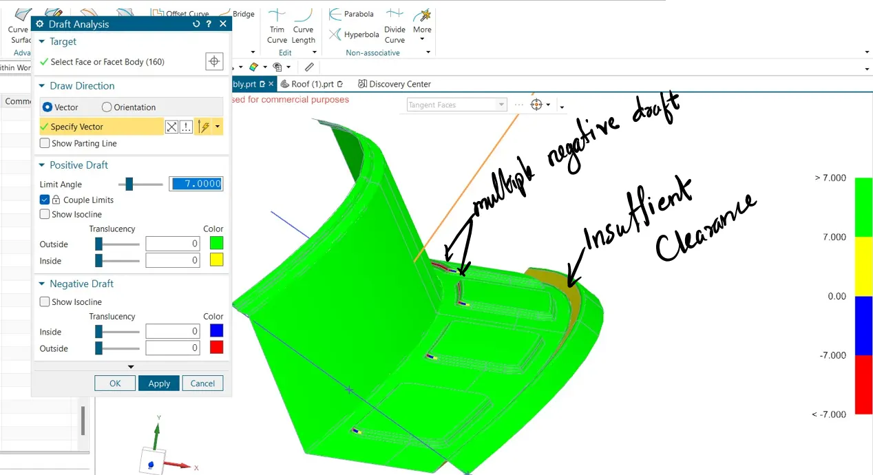
Initial design had some draft analysis issues, which was rectified using appropriate angle allowance in the corresponding section using law extension tool. The snaps of the draft analysis prior to changes are attached below;
<!-- [if gte vml 1]>
<!--[endif]--><!-- [if gte vml 1]>
<!--[endif]-->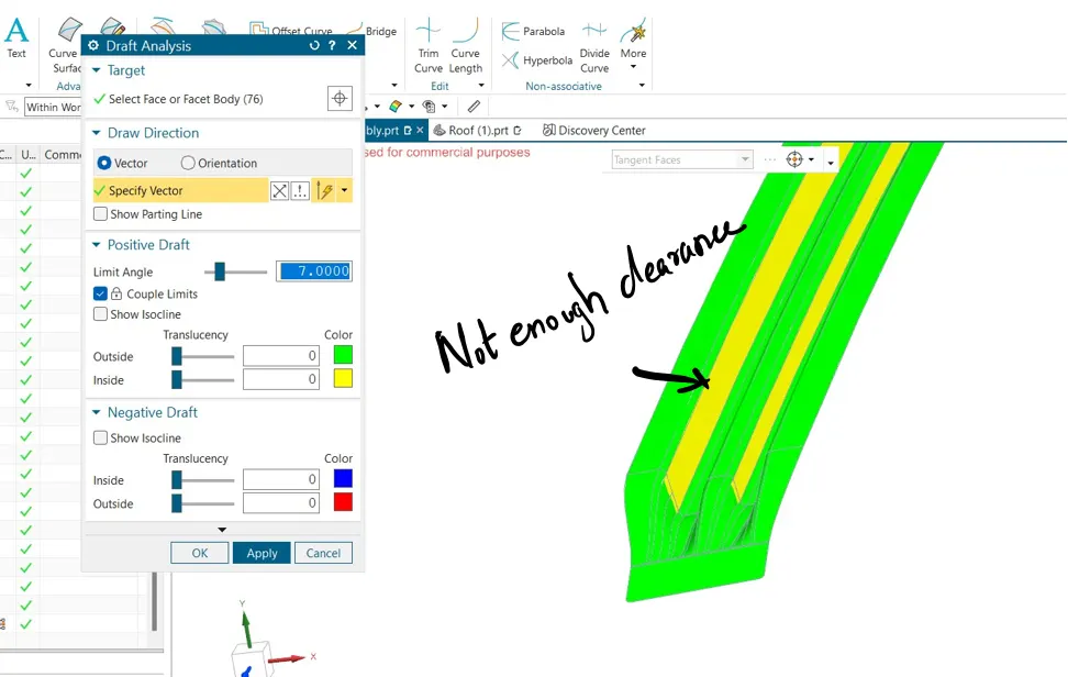
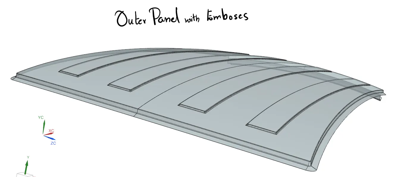
Additonally embosses were made in outer roof panel for strength impart. Ditch area was developed along the creation of rear roof rail to hide the BIW structure from the clients and to make the part more appealing.
After successful creation of the sheet metal structure, before aheading to pass the structure to CAE team, it’s advisable to calculate some of the critieria such as heat distortion and snow loading conditions from the designers perspective.
Curvature Study:
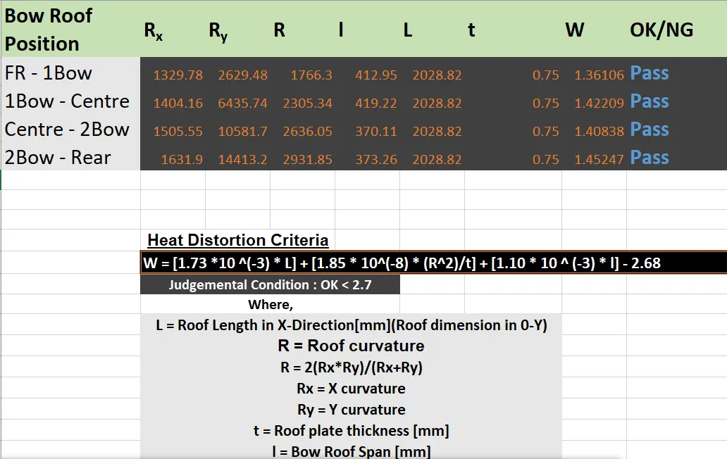
Conducted a curvature study on the roof surface to determine the values of Rx (X curvature) and Ry (Y curvature). These values are crucial for calculating the bow-roof position.
Bow-Roof Heat Distortion Calculation:
Calculated the heat distortion using the provided formula:
W = [1.73 x 10^(-3) x L] + [1.85 x 10^(-8) x (R^2)/t] + [1.10 x 10^(-3) x l] - 2.68
Where:
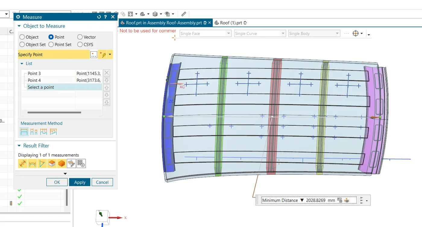
L = Roof Length in X-Direction
R = Roof curvature (calculated from Rx and Ry)
t = Roof plate thickness
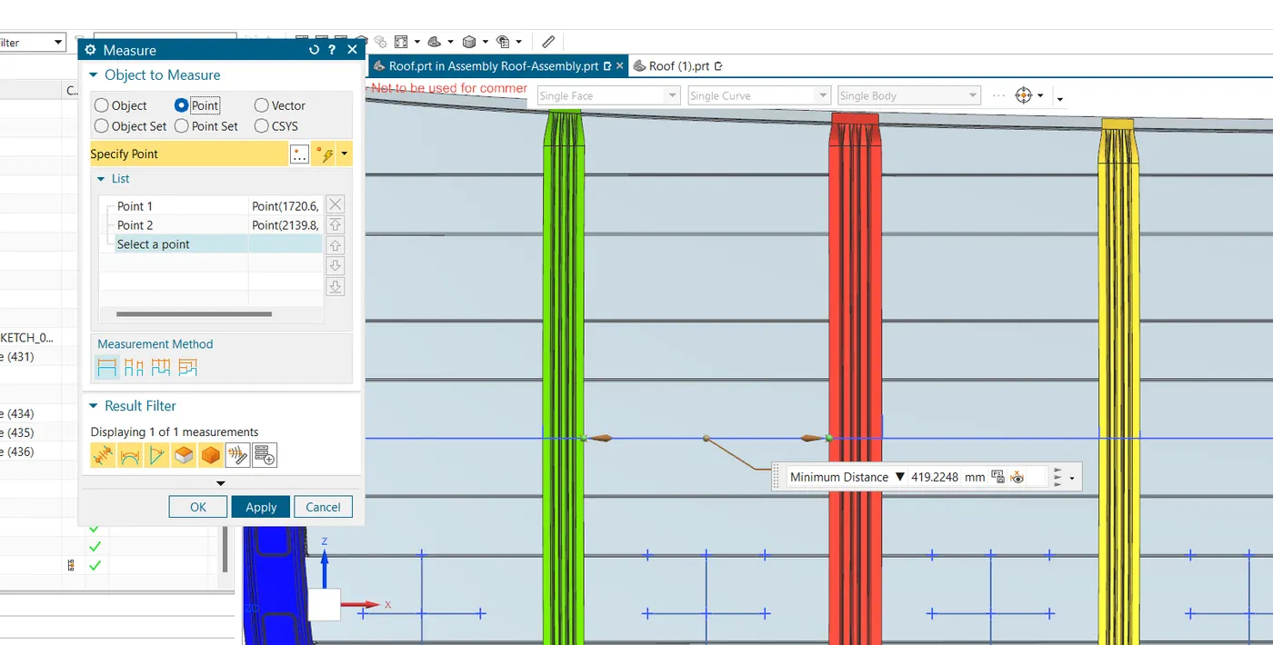
l = Bow Roof Span
Ensured that the calculated W value satisfies the judgment condition (W < 2>
Measuring screenshots are atatched below:
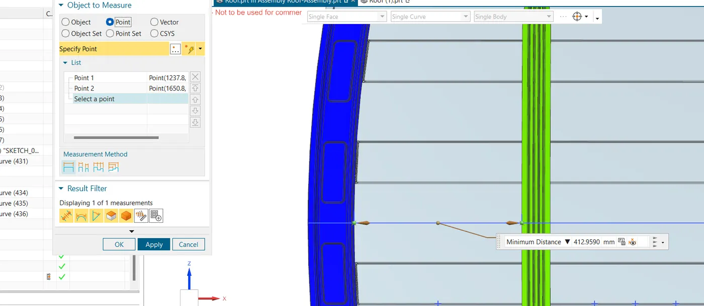
Similar study is done to review the roof structure on exposing to snow loading for countries having severe snowfall.
Snow Load Prediction:
Use the snow load prediction formula to calculate the Qr value:
Qr = [Iy x t^2] / [α x s x [(Rx + Ry)/2]^2 x 10^(-8)]
Where:
α = My x Lx^2 x 10^(-12)
t = Roof plate thickness
Ly = Distance between the front and rear roof rails
Lx = Distance between the Left and Right end of the roof on the Roof BOW
Y = Distance from Front Roof Rail to Roof BOW
s = Distance for which Roof BOW bears divided load
Iy = Geometrical moment of inertia of Roof BOW
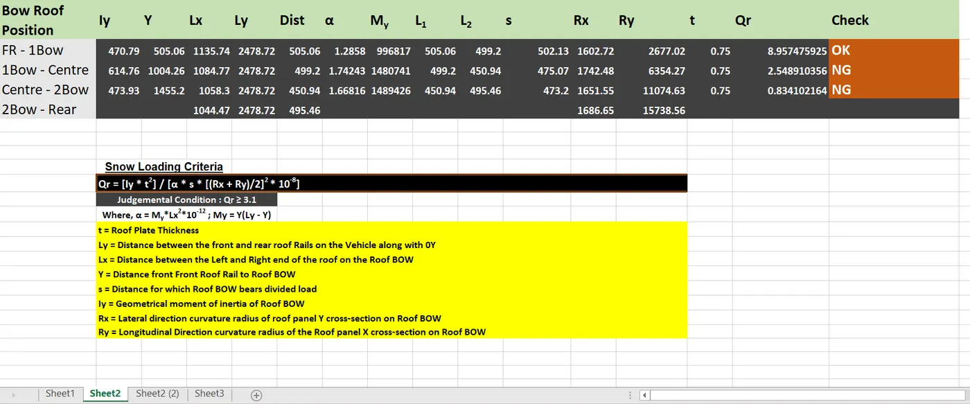
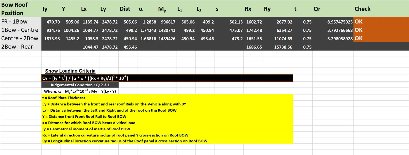
While ensuring that the calculated Qr values are meeting the judgment condition (Qr ≥ 3.1) it's founded that some reinforcements or additoinal roof rails are necessary for the design. So its advisable to increase the MOI(Moment of Inertia) of the roof rails and reinforcements to strengthen the roof panel to withstand the snow loading.
A study where increased MOI in data has shown to withstand the snow loading condition.
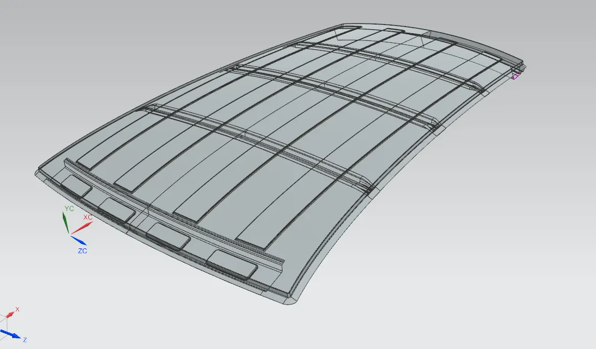
The project is finished by succesful creation of the CAD assembly of automotive roof panel along with all the necessary flanges in NX CAD.
To detail the manufacturing techniques of the automotive roof in short points;
- Stamping:
- Stamping is a widely used technique for producing roof panels, especially those made of steel or aluminum. Large presses are used to shape flat sheets of metal into the desired roof panel form.
- Progressive stamping processes can create complex shapes with high precision, while transfer stamping allows for multiple operations to be performed in different press stations.
- Extrusion:
- Extrusion is used to create roof components with consistent cross-sections, such as roof rails and trim pieces. This technique involves forcing heated material (usually aluminum) through a die to create the desired shape.
- Extruded aluminum roof rails, for example, are lightweight, corrosion-resistant, and offer excellent strength.
- Composite Materials:
- Composite materials, including carbon fiber reinforced composites, are increasingly used in the manufacturing of roof panels and components. They offer a combination of light weight and high strength.
- Composite roofs can be formed using various techniques, such as resin transfer molding (RTM) or compression molding, depending on the specific material and design requirements.
- Glass Roof Panels:
- Some vehicles feature panoramic sunroofs or full glass roof panels. Manufacturing these components involves precision cutting and shaping of laminated or tempered glass.
- Advanced glass bending techniques are employed to create curved roof glass components that seamlessly integrate with the vehicle's design.
- Joining Techniques:
- Welding, adhesive bonding, and fastening methods are used to join various roof components together. For example, spot welding may be employed to attach steel roof panels to the vehicle's body structure.
- Adhesive bonding is often used to attach glass panels to the roof frame, ensuring a secure and watertight seal.
- Die Casting:
- Die casting is used for producing roof components like brackets, hinges, and latches. It involves injecting molten metal into a mold cavity to create intricate shapes. Aluminum die casting is commonly used due to its lightweight properties.
Conclusion
The automotive car roof has evolved from a simple necessity to a multifaceted component that encompasses design, safety, and innovation. Its journey from open-air vehicles to hardtops and modern innovations reflects the dynamic nature of the automotive industry. As technology continues to advance, we can only anticipate further innovations in car roof design, ultimately enhancing the driving experience and safety for all. The car roof has truly come a long way, shaping the way we travel and enjoy our automobiles.