Roof Design
Roof Design
Objective:
- To the Given Roof styling, create an ASSEMBLY by developing the essential flanges for the outer roof and creating the reinforcements.
-
To Provide appropriate dimensions and check for Draft analysis.
-
To Do a curvature study on the roof and perform calculations to determine the position of the Bow-roofs.
-
To Develop the reinforcements as separate parts
Note:
-
Suggest and implement remedies in the design if the criterion is not full-filling.
-
Start with the creation of a roof ditch area with a tool opening angle of 7 degrees.
Introduction:
An automobile roof is the portion of an automobile that sits above the passenger compartment, protecting the vehicle occupants from sun, wind, rain, and other external elements.Under the styling surface that is seen on the outside, there are many other structures under the roof which contribute to its strength and stability. The number of such structures and supports differ with respect to the size of the vehicle. They are primarily installed on flatter areas of the roof to enhance the strength. These are the Front Roof Rail, Rear Roof Rail, Centre Roof Rail and Bow Roofs and they are joined to the roof by the Ditch Area.
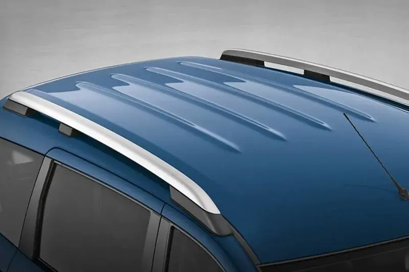
Types of car roofs:
An automobile roof or car top is the portion of an automobile that sits above the passenger compartment, protecting the vehicle occupants from sun, wind, rain, and other external elements. Because the earliest automobiles were designed in an era of horse-drawn carriages, early automobile roofs used similar materials and designs.
In later years, many variations on the automobile roof developed. These include:
Convertible roofs
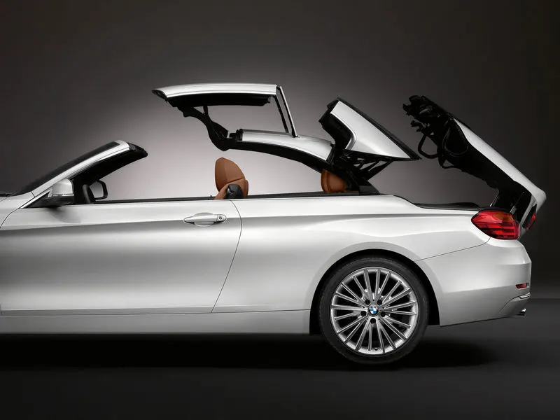
A convertible or cabrioletis a passenger car that can be driven with or without a roof in place. The methods of retracting and storing the roof vary among eras and manufacturers.
A convertible car's design allows an open-air driving experience, with the ability to provide a roof when required. A potential drawback of convertibles is their reduced structural rigidity (requiring significant engineering and modification to counteract the effects of removing a car's roof)
Hardtop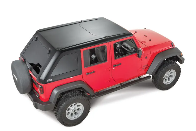
A hardtop is a rigid form of automobile roof, typically metal, and integral to the design, strength, and style of the vehicle. In limited cases a hardtop roof can be detachable (often designed to store in the trunk), or retractable within the vehicle itself.
Sunroofs
A sunroof is a movable panel that opens to uncover a window in an automobile roof, allowing light and fresh air to enter the passenger compartment. Sunroofs can be manually operated or motor driven, and are available in many shapes, sizes and styles. While the term "sunroof" is now used generically to describe any glass panel in the roof, the term "moonroof" was historically used to describe stationary glass panes rigidly mounted in the roof panel over the passenger compartment. A moonroof has a glass panel that is transparent and usually tinted. Previous terms include Sunshine Roof, Sliding Head and Sliding Roof.
T-tops
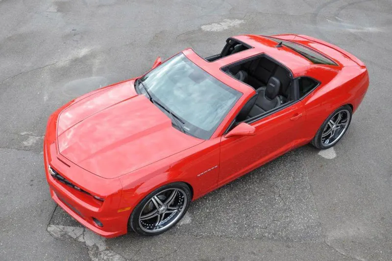
A T-top (UK: T-bar) is an automobile roof with a removable panel on each side of a rigid bar running from the center of one structural bar between pillars to the center of the next structural bar. The panels of a traditional T-top are usually made of auto grade safety glass.
Targa tops
Targa top, or targa for short, is a semi-convertible car body style with a removable roof section and a full-width roll bar behind the seats. The term was first used on the 1966 Porsche 911 Targa
Vinyl roofs
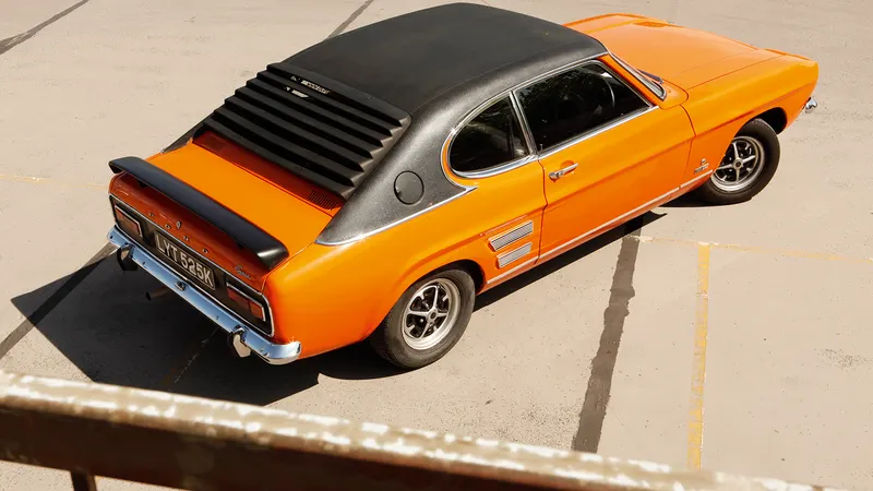
This covering was originally designed to give the appearance of a convertible to models with a fixed roof and eventually evolved into a styling statement in its own right. Vinyl roofs were most popular in the American market, and they are considered one of the period hallmarks of the 1970s domestic cars.
Manufacturing techniques used:
- Forging
- Stamping
- Spot Welding
- Hemming
Design Of Roof Includes:
- Roof Outer Panel
- Front Roof rail
- Rear Roof rail
- Bow Roof 1
- Bow Roof 2
- Center Roof rail
- Ditch Area
- Mastic Area
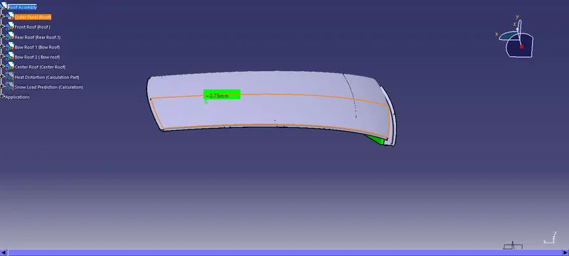
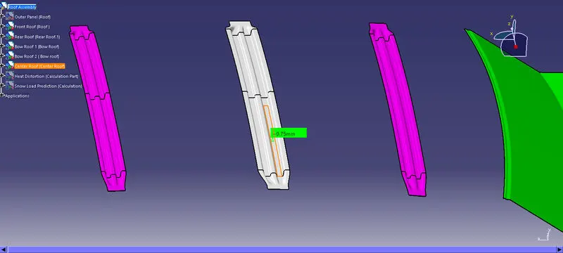
- Thickness of the roof = 0.75mm
- Draft Angle = >7 degree
Roof Outer Panel
Styling team provided the master section for the roof ditch area, front roof rail and rear roof rail as per the parameter of visibility criteria, head room clearance and other important parameter dimension like fitment of windshield, sealant rubber etc. All these data are well calculated in the planning stage to design the peripheral component accordingly. Thus, here designing is done just to replicate those input data considering engineering parameters which should be feasible for manufacturing. Master section of front and rear section.
Front & Rear Ditch Area
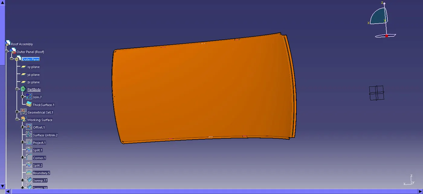
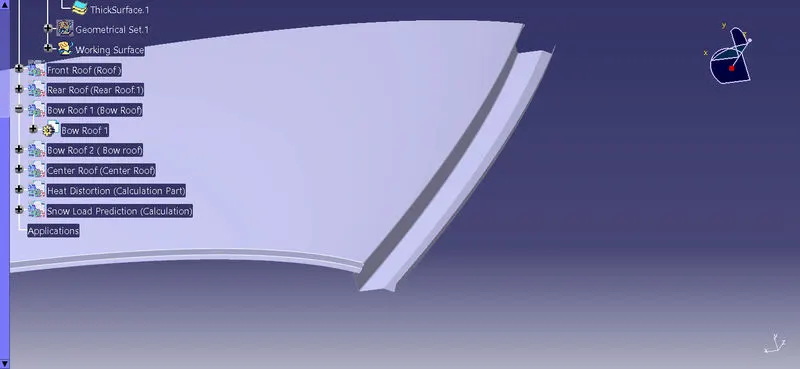
From dump solid part class A surface is extracted and ditch area are developed considering the parameter specified in the following master section.
Flange of around 15mm created with the law extension command, corner relief at rear flanges and positive draft more than 3 degree considering for the drawing operation process. Overall thickness of sheet metal consider 0.75mm throughout.
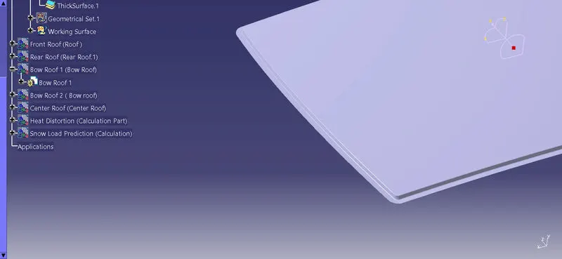
Surface is offset from the outer panel to form the ditch area and with the law extension command, corner relief at rear flanges and positive draft in required degree considering for the drawing operation process. Overall thickness of sheet metal for outer panel consider 0.75mm throughout.
Front roof rail
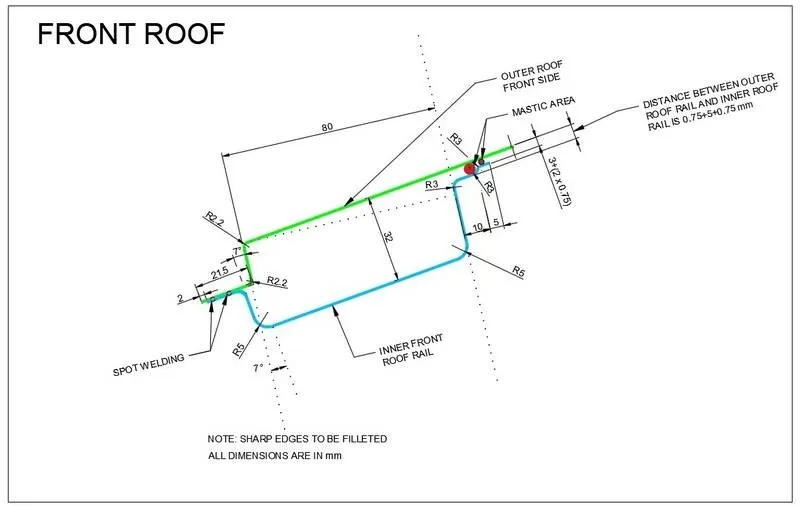
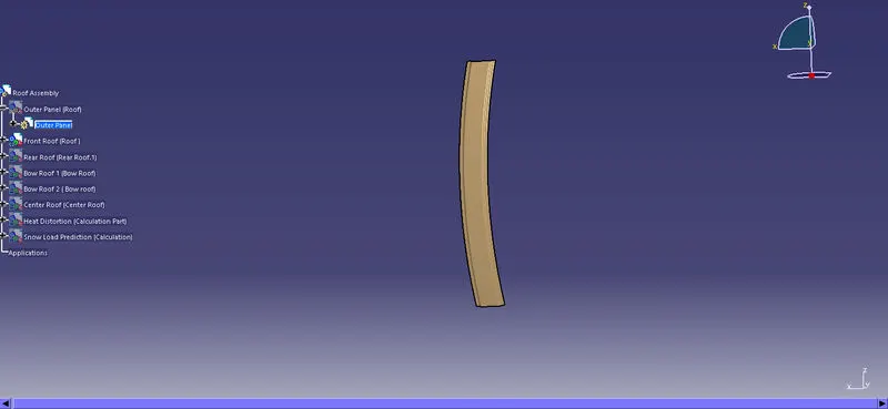
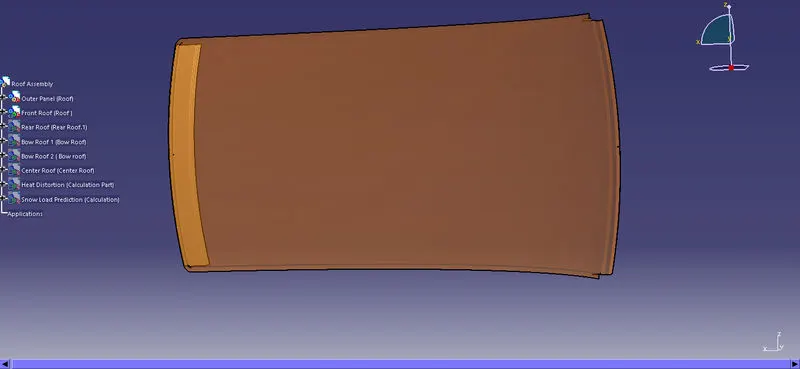
Front roof rail is provided at the front end of the roof to provide strength to that area of roof, while designing this part we should maintain the visibility and headroom clearance. The thickness of the centre bow roof is 0.75 mm thickness.
Front Roof Rail Master section
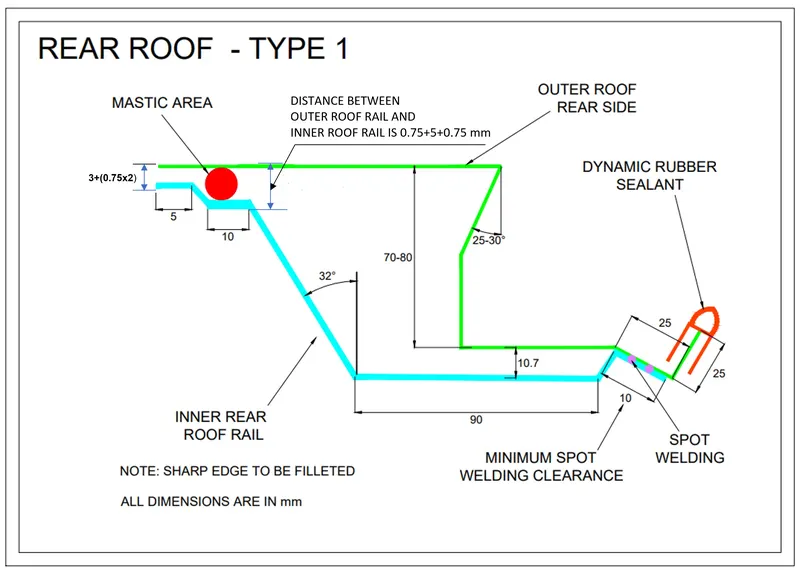
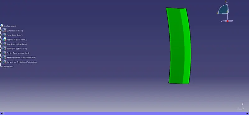
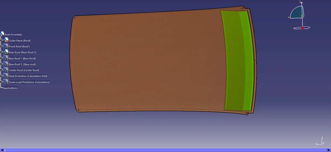
 Rear roof rail
It is provided at the rear part of the roof and it is joined with the outer roof by spot welding. We should take consideration of rear headroom and visibility criteria while desiging this. The thickness of the centre bow roof is 0.75 mm thickness.
Master section of the Rear Roof Rail
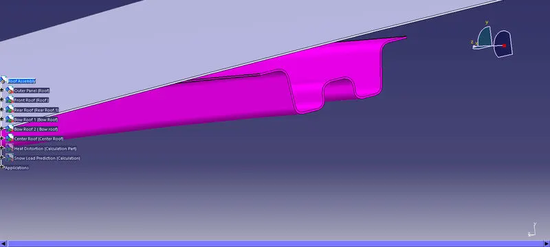
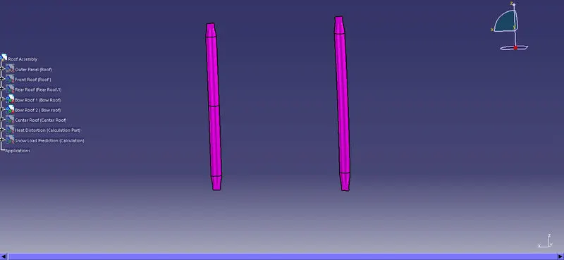
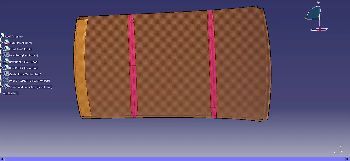
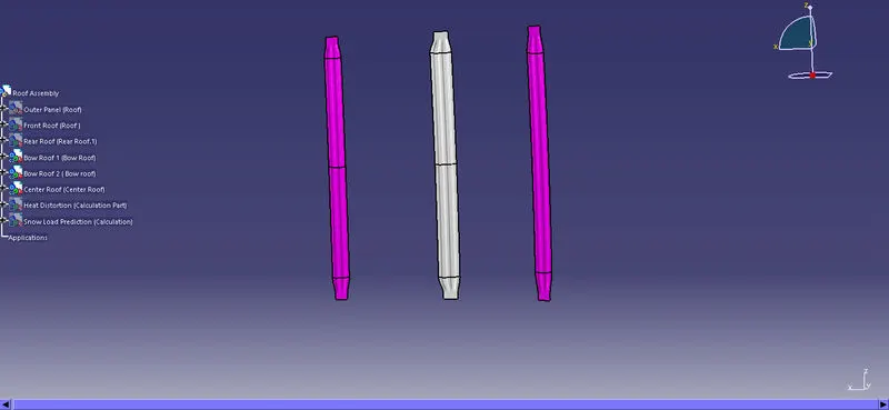
Bow Roofs
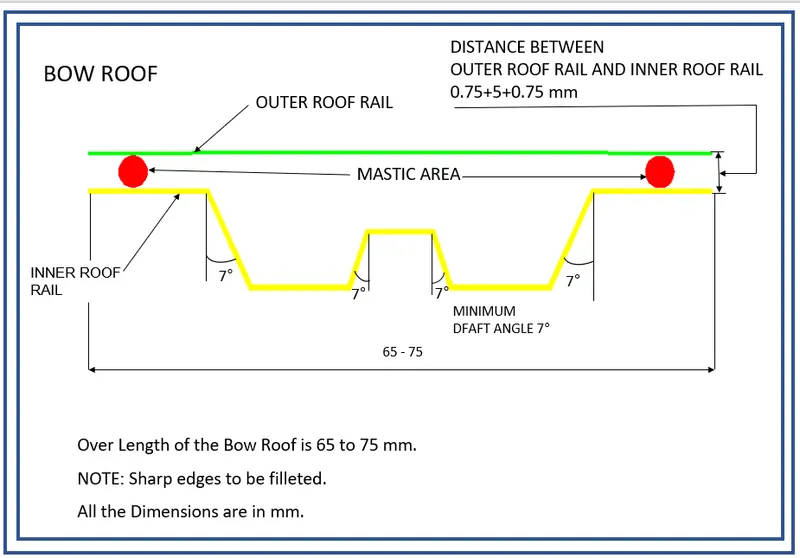
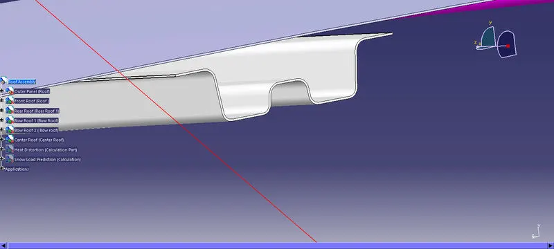
These additional roofs called bow roof are introduced to improve the torsional stiffness and load bearing capacity of the roof structure. The number of bow roof used varies by many factors, one to mention is the roof length.
Master section of Bow Roof
 Center Roof rail
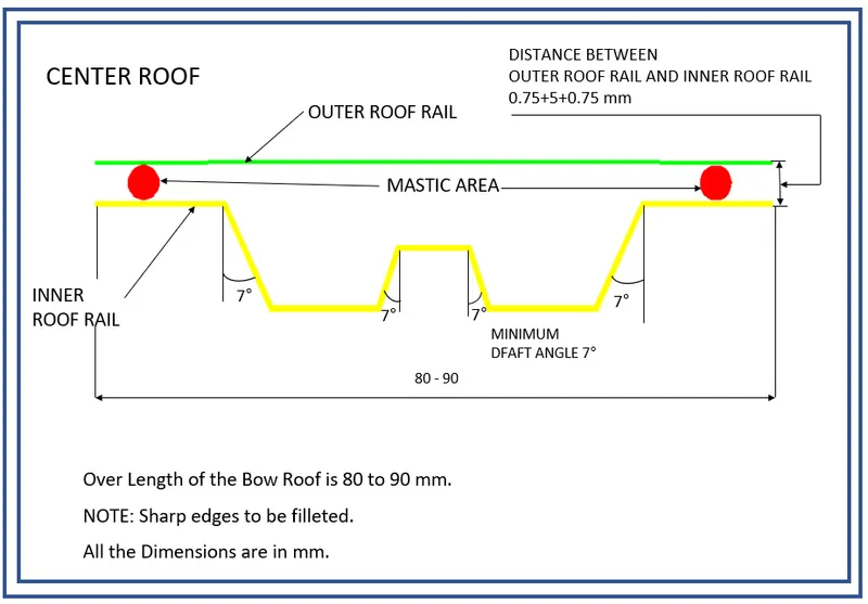
Centre roof rail is provided to effectively support the flat area of the roof as it is more susceptible to failure under the action of the load. Usually, the centre reinforcement roof rail will be placed at the centre of the roof connecting the B pillar support structure which results in added support in the roll-over test. The thickness of the centre bow roof is 0.75 mm thickness.
Master section of Center Reinforcement Rail
Mastic Area
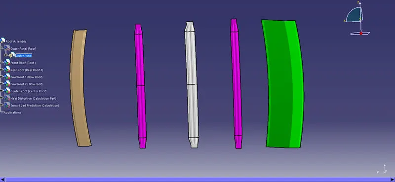
Bow Roof Rails and Centre Roof Rail are joined with the help of Mastic Sealant. Here we cant's use the Spot welding because it damages the A class area of the Roof. So, the mastic sealant is used in this area.
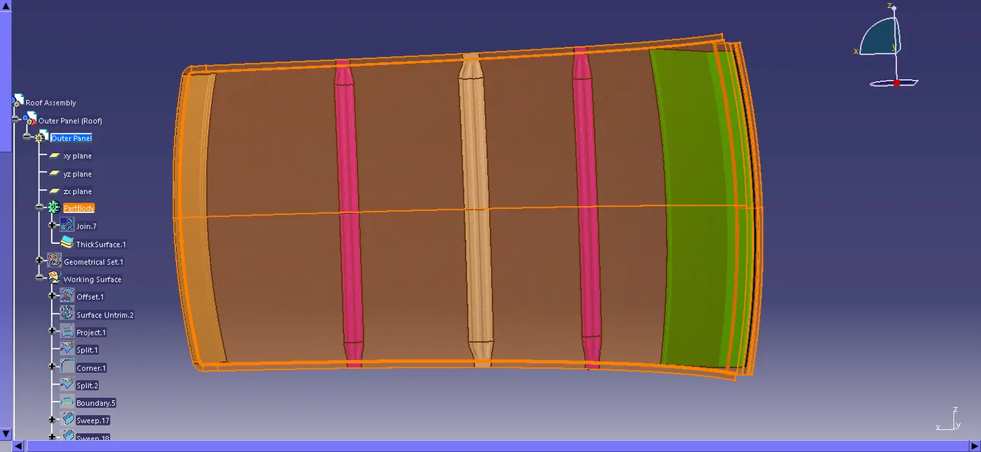
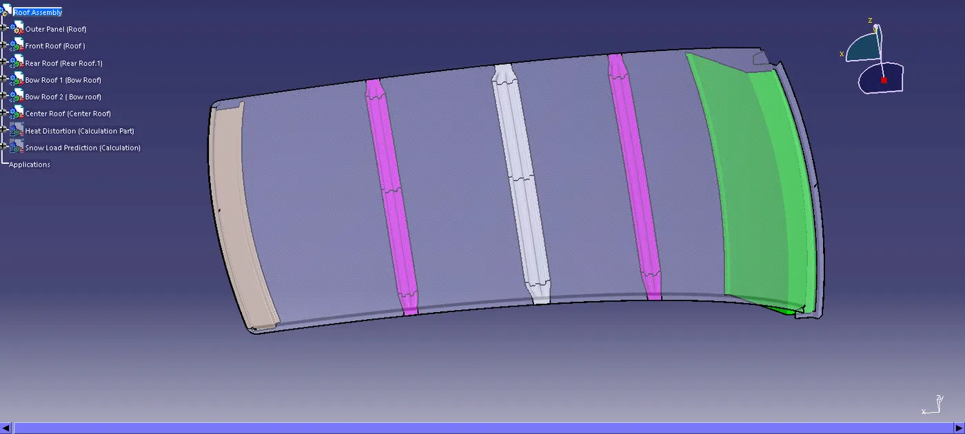 Roof Design Calculations:
For our study, we are considering the following conditions for testing the roof.
Heat Distortion Criteria:
The heat distortion study plays a major role in sheet metal usage. Heat distortion temperature is a temperature limit above which the material cannot be used for the structural applications. This study is used to predict the heat distortion temperature at where the material starts to soften when exposed to a fixed load at elevated temperature. In order to avoid bending or damages on the roof, based on the heat distortion temperature, this study will predict the bow roof position which helps to strengthen the roof.
Prediction Formula :
W = [1.73 x 10^(-3) x L] + [1.85 x 10^(-8) x (R^2)/t] + [ 1.10x10^(-3) x l] - 2.68
Where
L = Roof Length in X-Direction[mm](Roof dimension in 0-Y)
R = Roof curvature
R = 2(Rx*Ry)/(Rx+Ry)
Rx = X curvature
Ry = Y curvature
t = Roof plate thickness [mm]
l = Bow Roof Span [mm]
Judgement Condition : OK< 2.7
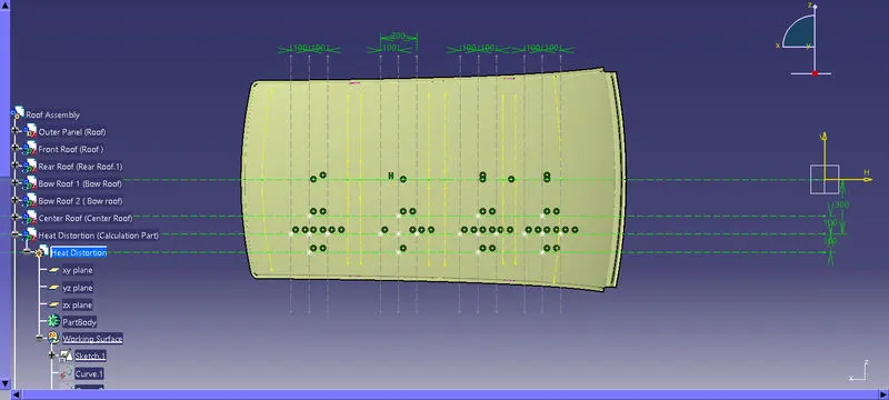
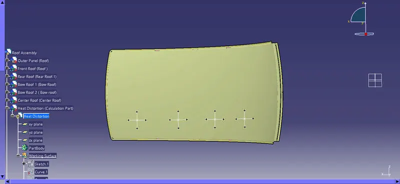
Reference Lines
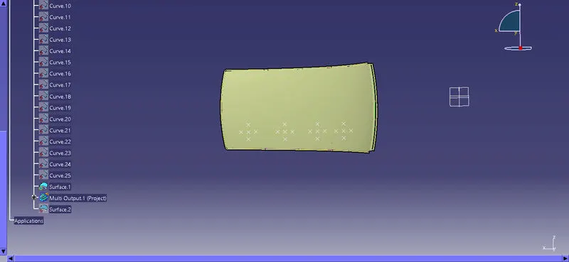
Projection Points
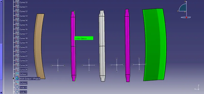
Creation of Arcs
Length Of Bow roofs
| Case | Name | Rx (mm) | Ry (mm) | L (mm) | I (mm) | R (mm) | t (mm) | W | Result |
| I | FR Roof - Bow Roof 1 | 14133.88 | 3349.896 | 2023.839 | 469.095 | 5416.11 | 0.75 | 2.060824187 | Pass |
| II | Bow Roof 1 - Center Roof | 9878.346 | 4118.129 | 2023.839 | 373.617 | 5812.935 | 0.75 | 2.065712239 | Pass |
| III | Center Roof - Bow Roof 2 | 6181.37 | 4975.042 | 2023.839 | 317.813 | 5512.987 | 0.75 | 1.920530316 | Pass |
| IV | Bow Roof 2 - Rear Roof | 3371.752 | 5632.947 | 2023.839 | 247.439 | 4218.442 | 0.75 | 1.532373946 | Pass |
From the above table, we can conclude that the positions at which the bow roofs are placed satisfy the heat distortion condition and is good to go for manufacturing.
Snow load Criteria:
This test is done to know how is the roof behaving when there is a snow over. Normally due to the snow weight the dent will happen. But the roof should be designed in such a way that when the snow is removal, the roof should go it its original position . This is the basic requirements for snow load criteria.
Qr = [Iy x t2] / [α x s x [(Rx + Ry)/2]2 x 10-8]
Where
α = My x Lx2 x 10-12 , My = Y(Ly-Y)
Judgement condition = Qr ≥ 3.1
250 ≤ s ≤ 380
t = Roof plate thickness [mm]
Ly = Distance between the front and rear roof Rails on the Vehicle along with 0Y[mm]
Length of Roof panel with the center point between Roof rail Front /Rear as the reference point of the front and the rear.
Lx = Distance between the Left and Right end of the roof on the Roof BOW [mm]
Width of the roof panel exposed on the surface.
Y = Distance front Front Roof Rail to Roof BOW[mm]
s = Distance for which Roof BOW bears divided load [mm]
s = L1/2 + L2/2
Iy = Geometrical moment of inertia of Roof BOW (Y cross-section )[mm4]
Rx = Lateral direction curvature radius of roof panel Y cross-section on Roof BOW [mm]
Roof panel curvature Radius of the Length Lx in Front view
Ry = Longitudinal Direction curvature radius of the Roof panel X cross-section on Roof BOW [mm]
Reference Lines
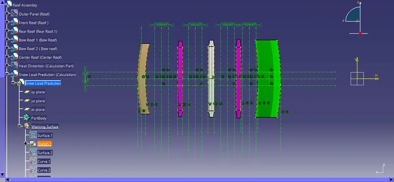
Projection of points
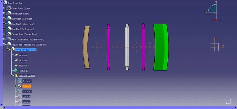
Surface Projection
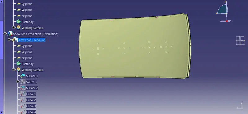
Rx and Ry
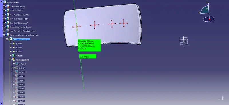
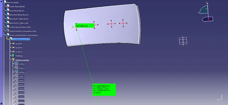
Lx and Ly

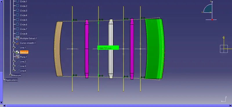
L1 and L2
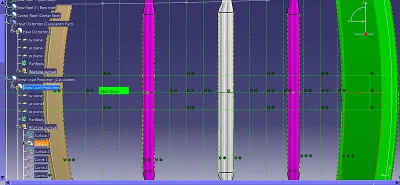
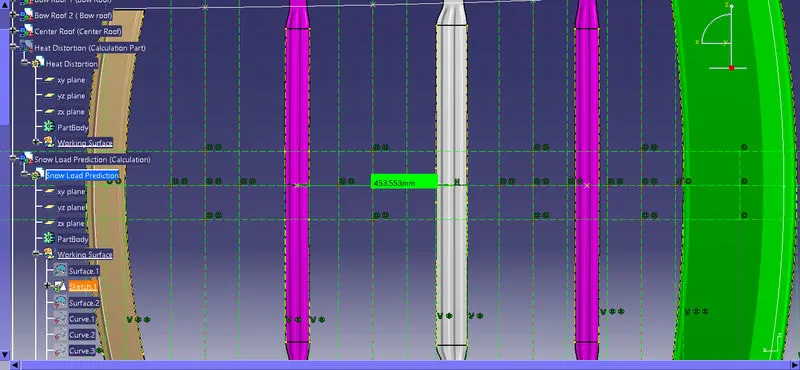
Moment Of Inertia
The moment of inertia, otherwise known as the mass moment of inertia, angular mass, second moment of mass, or most accurately, rotational inertia, of a rigid body is a quantity that determines the torque needed for a desired angular acceleration about a rotational axis, akin to how mass determines the force needed for a desired acceleration. It depends on the body's mass distribution and the axis chosen, with larger moments requiring more torque to change the body's rate of rotation.
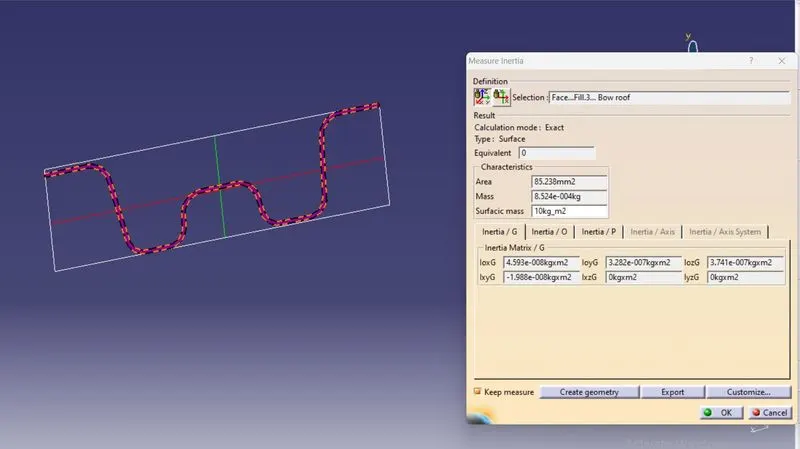
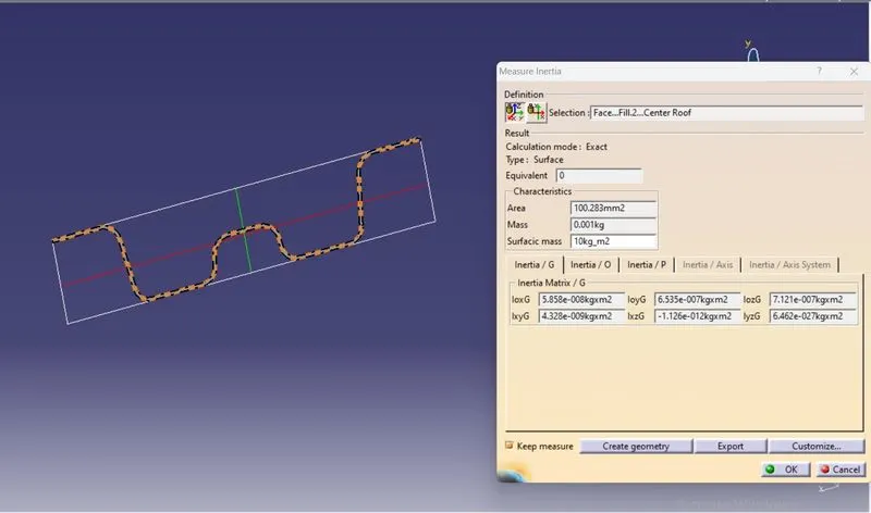
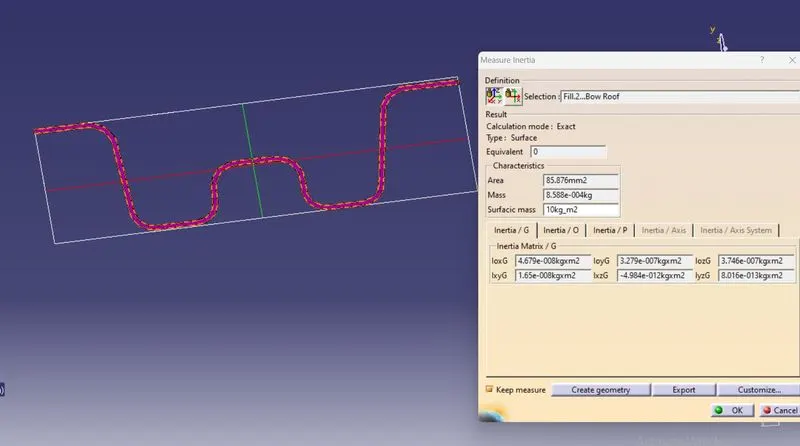
| Name | Rx (mm) | Ry (mm) | Lx (mm) | Ly (mm) | Y (mm) | My (mm) | Alpha | L1 (mm) | L2 (mm) | s (mm) | Iy ( mm^4) | t (mm) | Qr>=3.1 | Result |
| Bow Roof 1 | 2030.683 | 4064.879 | 1044.732 | 1859.949 | 560.72 | 728503.7 | 0.795136 | 560.72 | 453.553 | 507.1365 | 467.9 | 0.75 | 7.026541909 | Pass |
| Center Roof | 1740.277 | 4224.71 | 1060.701 | 1859.949 | 1014.273 | 857746.3 | 0.965039 | 453.553 | 397.933 | 425.743 | 459.3 | 0.75 | 7.069156844 | Pass |
| Bow Roof 2 | 3759.952 | 5984.731 | 1087.946 | 1859.949 | 1412.206 | 632305.4 | 0.748413 | 397.933 | 447.743 | 422.838 | 585.8 | 0.75 | 4.386124017 | Pass |
From the above table, we can conclude that the positions at which the bow roofs are placed satisfy the snow load criteria.
Draft Analysis
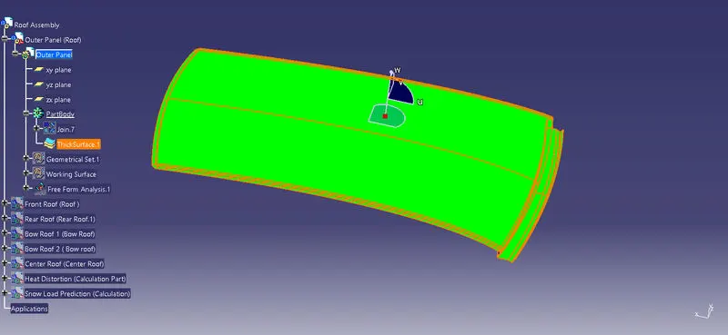
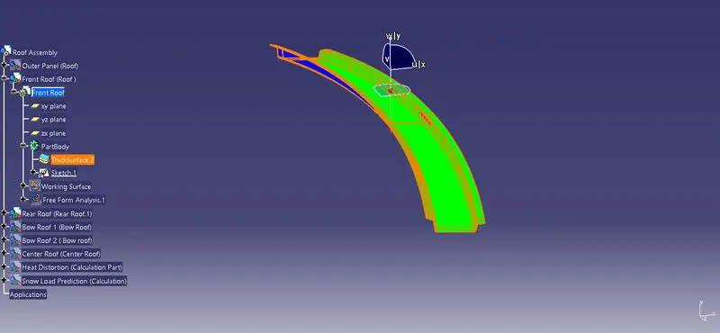
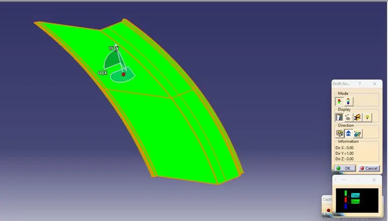
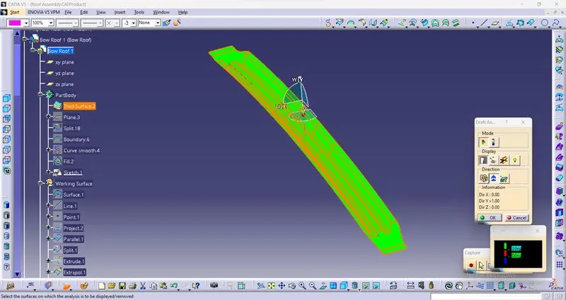
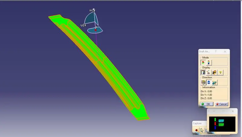
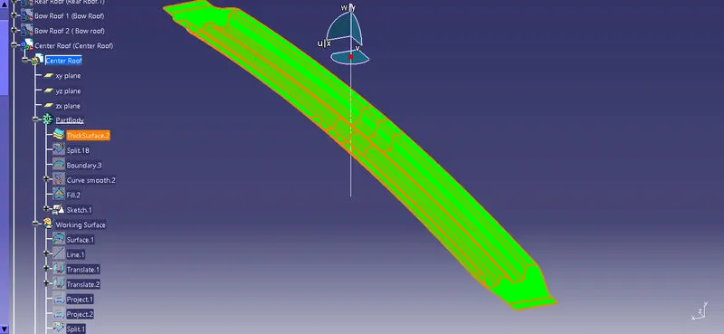
The Draft Analysis command enables you to detect if the part you drafted will be easily removed. This type of analysis is performed based on colour ranges identifying zones on the analysed element where the deviation from the draft direction at any point, corresponds to specified values.
Minimum draft angle of 7° is considered for analysis . Green colour infer on the parts that that all face along the tooling direction has positive draft angle greater than 7° and passed in analysis.
Roof Outer Panel
Front Roof Rail
Rear roof rail
Bow roof rails
Center roof rail
Conclusion:
Therefore, we designed the Roof Outer panel, Front Roof Rail, Rear Roof Rail, Bow roof 1 & 2 and Center Roof Rails according to the given master cross sectional drawing. Then Did a curvature study on the roofs and perform calculations for Heat Distortion and Snow Load Prediction has been done. As per the results Bow roofs Positions and strength are good. Finally verified the feasibility of manufacturing by draft analysis.