Roof Design
ROOF DESIGN
OBJECTIVE:
1.Main objective of the project is to create the Roof Sheetmetal design in NX cad, and also designing Front roof rail, rear roof rail, bow roof front, bow roof rear, center roof rail and Reinforcement are creating to build the strong roof.
2.Do curvature study on Roof and performance calculations for Heat distortion and Snow load criteria to determine the position of the Bow roofs.
3.Finding the moment of inertia and section modulus for Bow-roofs and center roof rail.
4.And, also finding the Draft Analysis of each part.
CAR ROOF
The car roof, also known as the roof panel or simply the roof, is the uppermost part of a vehicle that provides protection from the elements and supports the structural integrity of the car. It covers the passenger compartment and separates it from the exterior environment.The roof is typically made of metal, such as steel or aluminum, although some vehicles may use composite materials or even glass in certain areas. It is designed to be strong enough to withstand the weight of the car and any additional loads, such as luggage or roof racks.
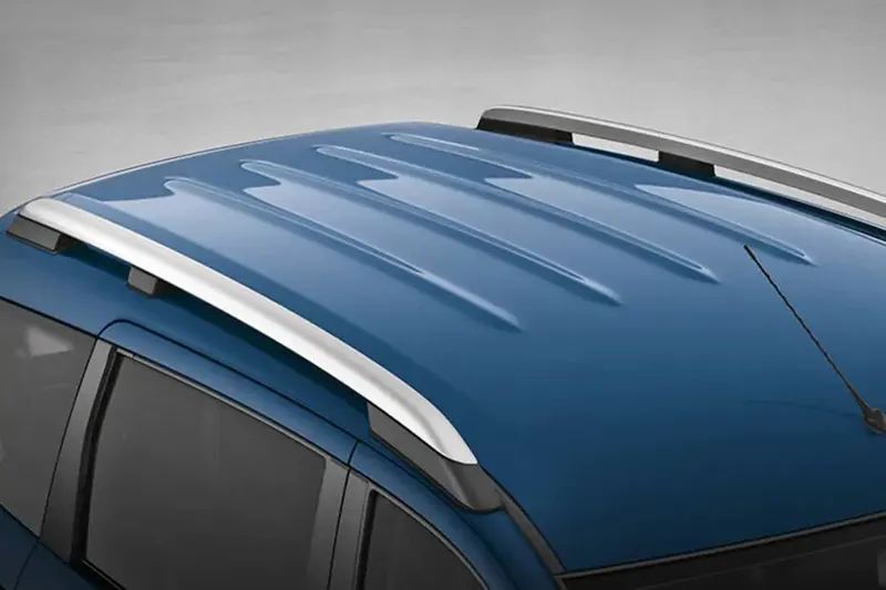
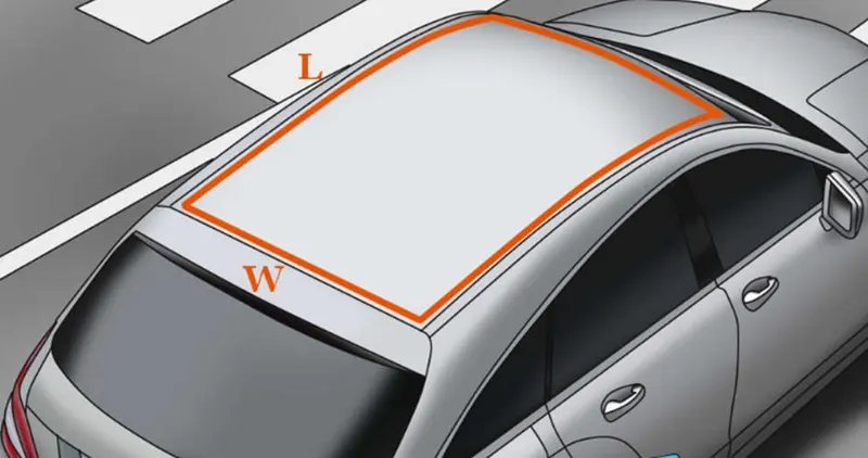
Car roofs can have various designs, including sedan roofs that slope down towards the rear of the vehicle, hatchback roofs that extend all the way to the rear end, or SUV roofs that may have a more upright and spacious design. Some cars also feature sunroofs or moonroofs, which are panels that can be opened or have a transparent section to allow natural light into the interior.It's worth noting that electric and hybrid vehicles sometimes have unique roof designs to accommodate battery packs or improve aerodynamics for better energy efficiency.Overall, the car roof is an essential component of a vehicle's structure, providing protection, aesthetics, and functionality.
TYPES OF CARS ROOF
HARDTOP ROOF: This is the standard type of car roof found in most vehicles. It is made of solid metal or other rigid materials, providing a fixed and sturdy structure.

SOFT TOP ROOF: Soft tops are typically made of fabric or vinyl and can be manually or electrically operated to open or close. They are commonly seen in convertible cars or certain sporty models, allowing the driver and passengers to enjoy an open-air driving experience.

TARGA ROOF: A Targa roof is a removable panel that covers the front seats of the car, leaving the rear section open. It is often made of a rigid material, such as metal or composite, and is commonly found in sports cars like the Porsche 911 Targa.

PANORAMIC ROOF: A panoramic roof is a large, usually fixed, glass panel that spans a significant portion of the car's roof. It provides an expansive view of the sky, allowing more natural light into the interior and giving passengers a sense of openness. Panoramic roofs are becoming increasingly popular in many modern vehicles.

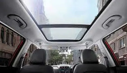
SUNROOF/MOONROOF: Sunroofs and moonroofs are typically smaller, movable panels located in the car's roof. They can be manually or electrically operated to open or tilt, providing ventilation and natural light into the cabin. Sunroofs are typically solid, while moonroofs have a glass panel, allowing passengers to see the sky even when closed.

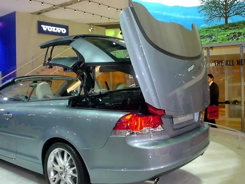
RETRACTABLE HARDTOP: Retractable hardtop roofs combine the benefits of a hardtop roof and a convertible. They are typically made of multiple rigid panels that fold and retract into the trunk with the press of a button, transforming the car from a closed coupe to an open convertible.
VEHICLE PREPARATION OF ROOF TEST
Preparing a car roof for testing typically involves several steps to ensure safety and accuracy. Here's a general guideline for vehicle preparation for a car roof test:
-
OBTAIN THE NECESSARY EQUIPMENT: Depending on the specific test, you may need specialized equipment such as a roof rack, load-bearing frame, or instrumentation.
-
CLEAR THE ROOF AREA: Remove any loose objects, such as roof racks, roof boxes, or antennas, from the vehicle's roof. Make sure the surface is clean and free of debris.
-
CHECK THE VEHICLE CAPACITY: Before conducting any test that involves adding weight to the roof, ensure that the vehicle's weight capacity is not exceeded. Consult the vehicle's owner's manual or contact the manufacturer for specific weight limits.
-
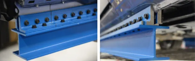
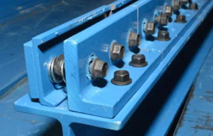
INSTALL A ROAD BEARING FRAME OR FIXTURE (if required): In some cases, you might need to install a load-bearing frame or fixture to simulate specific conditions or distribute the load evenly. Follow the manufacturer's instructions for proper installation.
-
SECURELY ATTACH INSTRUMENTATION (if necessary): If you need to measure forces, vibrations, or other parameters during the test, ensure that any instrumentation is securely attached to the roof and properly calibrated. Follow the manufacturer's guidelines for installation and calibration.
-
VERIFY STRUCTURAL INTEGRITY: Before conducting the actual test, visually inspect the vehicle's roof for any signs of damage or weakness. Check for dents, cracks, or other structural issues that could affect the test results or compromise safety. If you have concerns, consult a professional or contact the vehicle manufacturer.
-
FOLOW SAFETY PROTOCOLS: Always prioritize safety during the preparation and execution of any test. Use appropriate personal protective equipment (PPE), follow established safety procedures, and have an emergency plan in place.
-
CONDUCT A PRE TEST CHECK: Double-check that all equipment, instrumentation, and fixtures are properly secured and functioning correctly. Confirm that the vehicle is ready for the specific test conditions.
TESTING
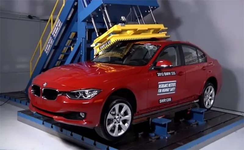
- Roof strength evaluations are conducted on a quasi-static test system manufactured by MGA Research Corporation.
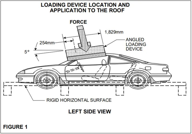
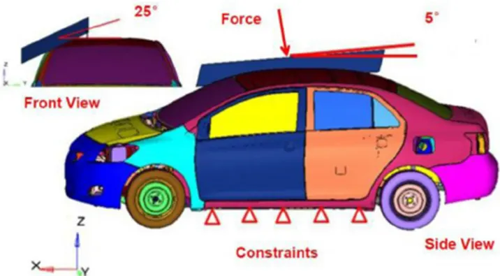
- The system consists of an upright assembly and an attached loading head that can be fixed at varying heights from the ground and at pitch angles ranging from −5 to +5 degrees to accommodate testing on the driver or passenger side. The roll angle is permanently fixed at 25 degrees. Four hydraulic actuators control the movement of the platen along two linear guides.
- The entire system is mounted on a T-slot bed plate anchored to the floor of the test facility.
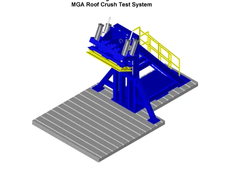
- Two I-beams (HR A-36 W10x88) are mounted on the bed plate perpendicular to the longitudinal axis of the platen.
- The vehicle, with the attached rocker panel support system, is placed on these beams.
- The vehicle is adjusted so that The longitudinal centerline of platen is within 10 mm of the initial roof contact point.
- The yaw angle of the vehicle relative to the longitudinal axis of the platen is 0 ± 0.5 degrees.
- The midpoint of the platen’s forward edge is 254 ± 10 mm beyond the most forward point of the roof (including the windshield trim if it overlaps the roof) lying on the vehicle’s longitudinal centerline.
- To minimize the potential for loading the edge of the platen during the test, there should be a minimum clearance of 150 mm between every point along the forward edge of the platen and the structurally significant body components, when measured normal to the platen’s face.
- Structurally significant body components include the roof, roof pillars, and any glass (windshield, side windows, roof glass) but not the side mirrors, trim, removable roof rails, roofmounted antennas, and generally any component that consumers can remove.
- If the 150-mm clearance is not achieved, then the vehicle is moved rearward longitudinally until the 150-mm clearance is achieved at the front edge of the platen, or an equal measure of clearance (±20 mm) less than 150 mm at the front and rear edges of the platen is obtained whichever occurs first.
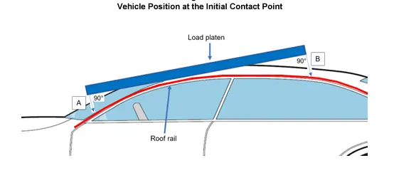
- The pitch angle of the vehicle matches the on-road angle, while also accounting for any difference between the platen’s pitch angle and the nominal −5 degrees.
- The maximum combined difference of the vehicle and platen pitch angles from their targets is ± 0.5 degrees. (For example, if the on-road vehicle pitch angle is −0.2 degrees and the platen pitch angle is −5.2 degrees, the target sill angle for the test is −0.4 ± 0.5 degrees.)
- If necessary to achieve this angle, shims are inserted between the rocker panel supports and the W10x88 Ibeams attached to the bed plate. Once the vehicle is positioned correctly, the rocker panel supports are clamped to the two perpendicular Ibeams, and the beams are marked to confirm that the vehicle position is maintained during the test.
- For body-on-frame vehicles, the frame is supported to prevent the weight of the chassis from stressing the body at the body mounts. The roof is crushed to a minimum displacement of 127 mm at a nominal rate of 5 mm/second. Some tests are conducted to a greater displacement to collect additional strength data for research purposes.
- Force data are recorded from five load cells (Interface Inc., model 1220) attached to the loading platen. Displacement data are recorded from four linear variable displacement transducers (LVDTs) (MTS Temposonics model GH) integrated into the hydraulic actuators.
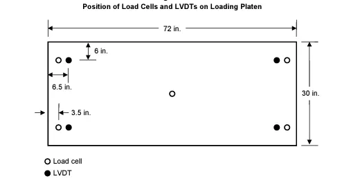
Force and displacement data are collected with a National Instruments USB-6210 data acquisition system and reported at 100 Hz. These data are based on a sampling rate of 2,000 Hz, with every 20 points being averaged to produce the output data at 100 Hz. The displacement-time histories from the LVDTs are compared to verify that the platen’s roll angle and pitch angle (relative to the vehicle’s on-road pitch) were maintained at 25 ± 0.5 degrees and −5 ± 0.5 degrees, respectively.
The precrash and postcrash conditions of each test vehicle are documented with still photographs. The position of the vehicle in the test fixture also is recorded. Motion picture photography is made of the test with real-time video cameras.
CALCULATING THE STRENGTH-TO-WEIGHT RATIO (SWR) RATING
- Force and displacement data are recorded for 5 seconds prior to each test, while the test system holds the loading platen at initial roof contact. The data recorded from 1 to 4 seconds of this hold time are averaged for each channel to produce a measurement offset that is subtracted from the data recorded during the crushing of the roof.
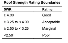
- After removing the offset for each channel, the force-displacement curve is plotted using the summed output from the five load cells and the average displacement from the four LVDTs. The maximum force prior to 127 mm of platen displacement is divided by the measured curb weight to obtain the SWR. Both the force and curb weight are rounded to the nearest pound prior to performing the calculation, and the resulting SWR is rounded to the nearest one-hundredth of a unit. Displacement is rounded to the nearest 0.1 mm. (The maximum displacement where the load can be used for the vehicle rating is 126.9 mm.) The vehicle’s rating is assigned based on the boundaries listed in the below table.
- All trim levels sharing the tested vehicle’s body type and roof structure are assigned the same rating as the typically equipped trim level, provided their curb weights do not exceed 110% of the selected vehicle’s weight. Based on published curb weights from multiple sources, any trim levels that may exceed this weight are identified and weighed.
- If the weight does exceed 110% of the weight of the selected vehicle, a unique SWR is calculated for that trim level.
- If this SWR results in a lower rating, both ratings are reported for the model, with a split according to trim level. If a trim level weighs more than 110% of the typically equipped model, but the lower SWR does not fall in a lower rating band, only the original SWR and rating are reported for the model.
TYPES OF CAR ROOF TESTING
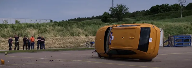
Car roof testing is an essential part of vehicle safety evaluation to ensure that roofs meet certain standards for occupant protection in the event of a rollover accident. Here are some common types of car roof testing:
ROOF CRUSH RESISTANCE TEST: This test evaluates the roof's ability to withstand a certain amount of force without significant deformation or collapse. A hydraulic press applies force to a specific area of the roof, gradually increasing the load until a specified deformation limit or a predetermined load threshold is reached. The test measures the roof's structural integrity and its ability to protect occupants from injury during a rollover accident.
ROLLOVER STABILITY TEST: Rollover stability tests evaluate a vehicle's propensity to roll over during extreme maneuvers. They may involve dynamic tests, such as a J-turn test, where the vehicle is driven at high speeds and then suddenly steered to simulate emergency evasive maneuvers. These tests assess the vehicle's stability and rollover potential, which indirectly impacts roof integrity.

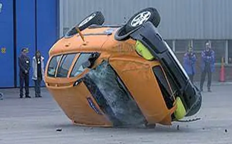
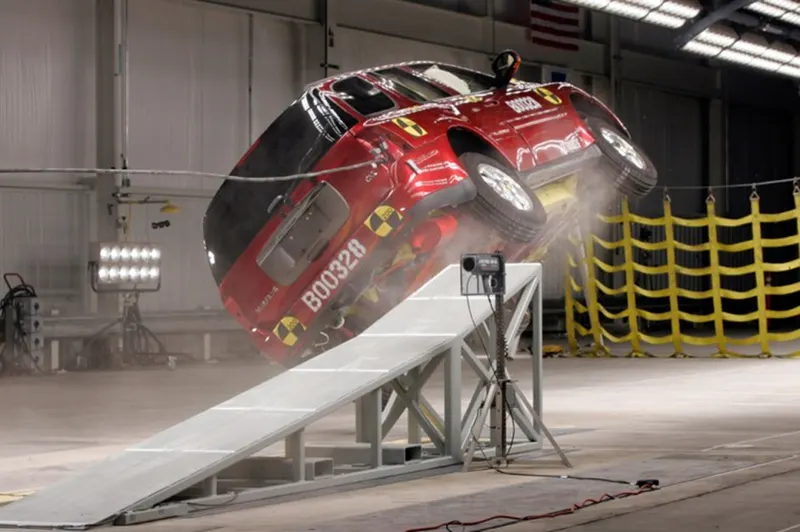
ROOF STATIC LOAD TEST: In this test, a static load, often in the form of a weight or weights, is applied to the vehicle's roof. The load is typically several times the vehicle's weight, and it is applied to different points on the roof to simulate the worst-case scenario of a rollover accident. The test ensures that the roof structure can handle significant loads without excessive deformation or failure.
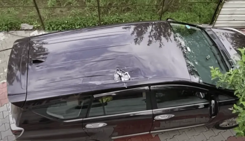
ROOF PENETRATION TEST: This test evaluates the roof's resistance to objects that may penetrate the roof during a rollover accident, such as tree branches or debris. A pointed or rounded probe is dropped from a specific height onto different areas of the roof to assess its resistance to penetration. The test ensures that the roof can provide adequate protection by preventing objects from entering the passenger compartment.
ROOF RETENTION TEST: The roof retention test assesses the ability of the roof to remain attached to the vehicle's body during a rollover accident. It involves applying dynamic forces to the roof structure by tilting the vehicle to different angles. The test ensures that the roof does not detach or separate from the vehicle, which could increase the risk of occupant ejection or injury.
ROOF DESIGN
ROOF
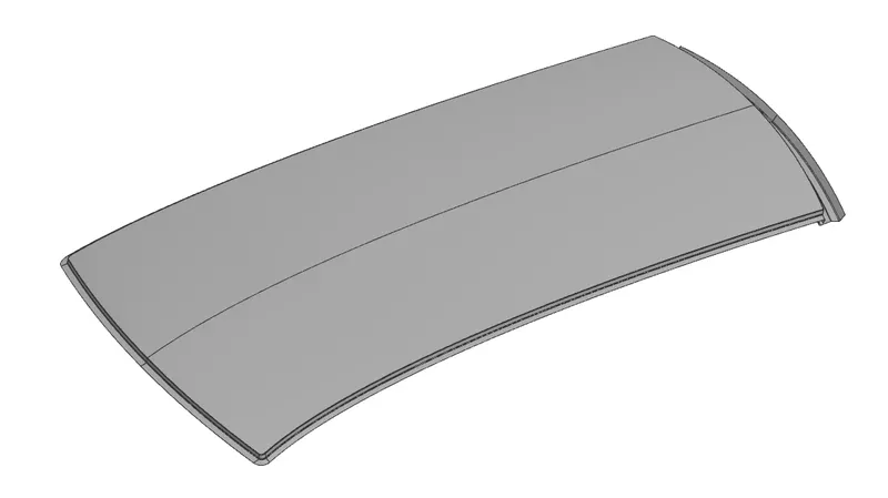
Now we want to design the roof and roof reinforcements by using the NX CAD.
The given data for the roof design.
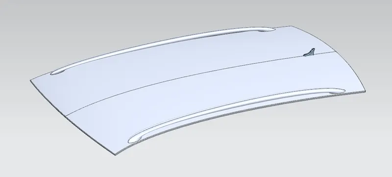
Now we want to extend the front and rear side of the roof using the wave geometry linker,law extension and trim sheet.
Want to create the front and rear ditch area on the two sides of the roof.
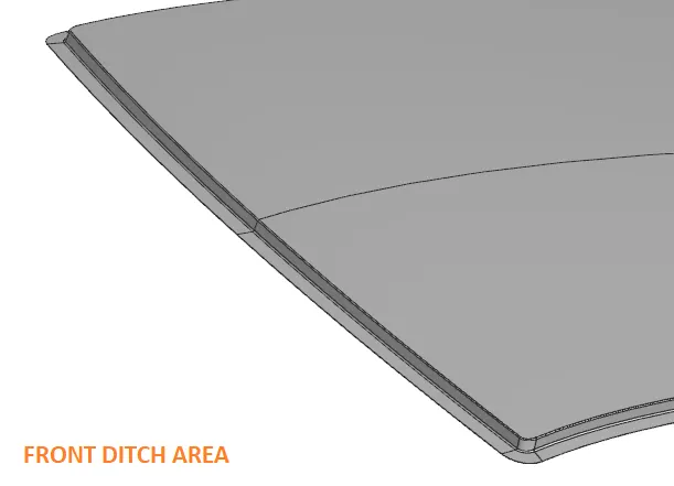
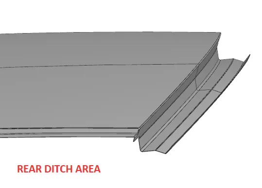
Roof has been completely designed.
FRONT ROOF RAIL
Front roof rail is used for supporting the roof for externally applied forces occurring at accidents. When we increasing the front roof rail is good for strength but also it is not for drivers because of it hide visibility of road.
When considering the parameters of roof rail proper draft angle and also using the embosses for increasing the strength. Front section of front roof rails spot welded to the front ditch area and other end is fixed with help of mastic sealants.
Given master section for the front roof rail.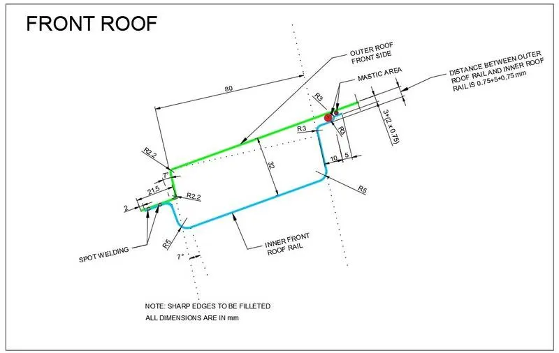
Front roof rail have been designed according to the given master section.
THICKNESS OF THE SHEET METAL:0.75mm
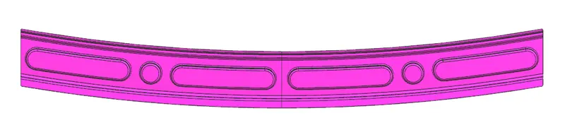
EMBOSS HEIGHT:4mm
OVERALL LENGTH OF THE FRONT ROOF RAIL:1082mm
RADIUS GIVEN FOR SHARP ENDS:2.2mm,3mm and 5mm
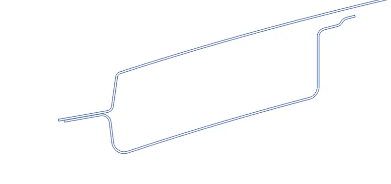
Final design of the front roof rail.
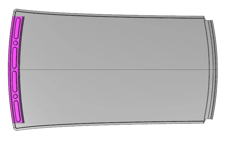
Obtaines master section from the designed roof.
REAR ROOF RAIL
Rear roof rail is creating to length with proper draft angle. Give embosses on the sheet to ensure the enough strength for holding the roof structure. When considering the all parameters like length, width, sealants, rubber materials, wind shield to create the design properly.
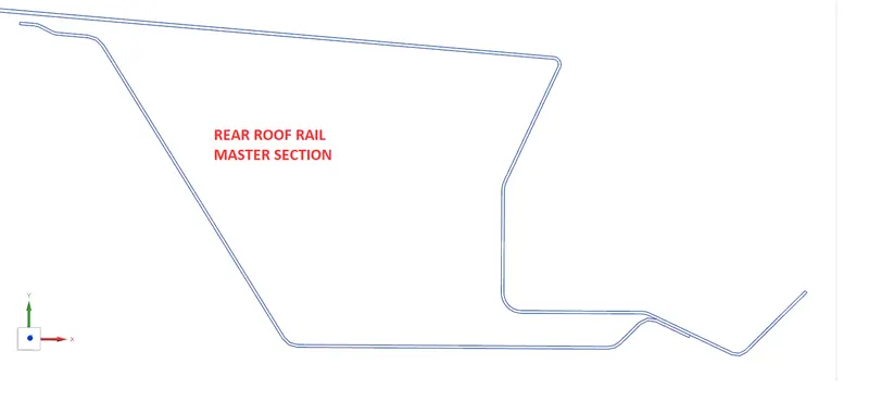
Given master section for the rear roof rail.
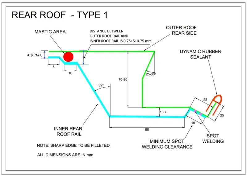
THICKNESS OF THE SHEET METAL:0.75mm
EMBOSS HEIGHT:4mm
RADIUS GIVEN FOR SHARP ENDS:2.2mm,3mm and 5mm
Rear roof has been designed according to the given master section.
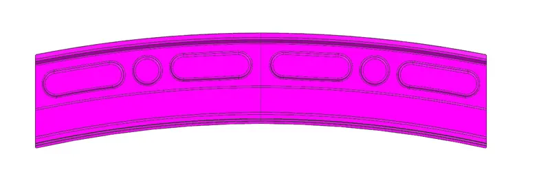
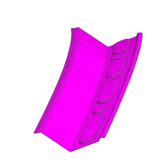
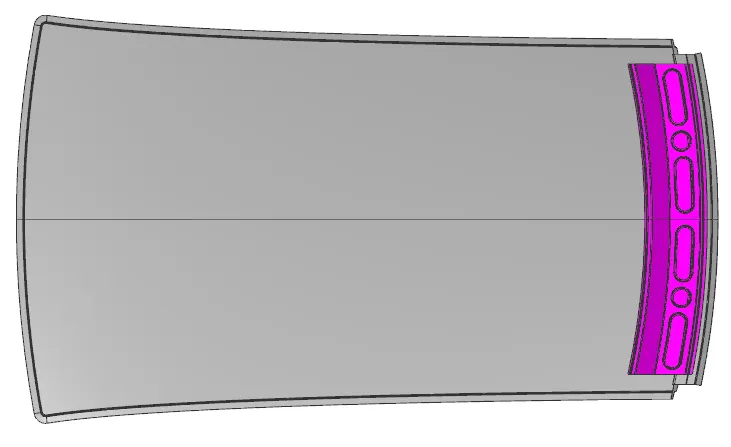
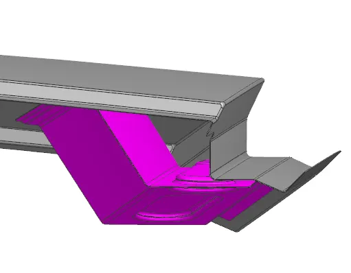
Obtained master section from the designed surface.
CENTER ROOF RAIL
Reinforcement Center roof rail is effective support to the flat area structure roof. Because of center area of roof is more susceptible to failure under action of load. Usually, Reinforcement center roof rails are fixed at the center of the roof for connecting to the B – Pillar support structure, it will used for roll-over test.
Center bow roof and reinforcements are placed at the center of the roof structure. They two are connecting to help of spot - welding operation. Thickness of the Reinforcement center roof rail is 0.75mm.
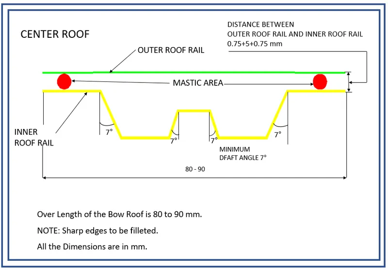
THICKNESS OF THE SHEET METAL:0.75mm
EMBOSS HEIGHT:4mm
RADIUS GIVEN FOR SHARP ENDS:2.2mm,3mm and 5mm
Center roof rail has been designed according to the given master section.

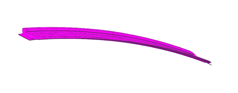

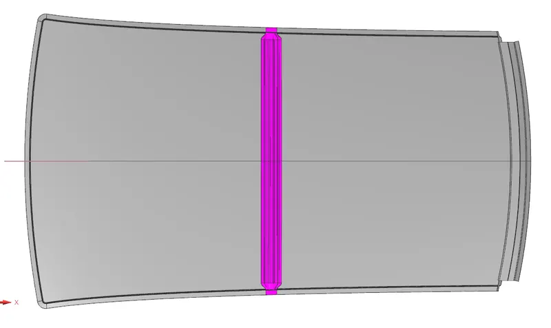
Obtained master section for the designed surface.
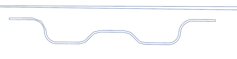
BOW ROOF FRONT:
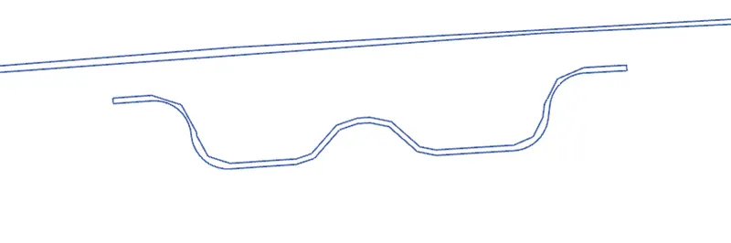
The bow roofs are given to the improve the torsional stiffness and load bearing capacity of the roof structure. When number of bow roofs are given by the roof dimension. Longer the roof area we have to give the more bow roof to the structure.Positioning of the bow roofs are decided by the curvature study. The Heat distortion and Snow load criteria are checked to analyze the bow roof position by various condition.We also give the Mastic area for fixing the Bow roof to the roof outer. Each mastic sealants are having 80mm circular effective area of surroundings. Thickness of the Bow roof is 0.75mm.
Master section for the bow roof rail
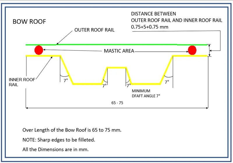
With the given master section the bow roof have been designed.

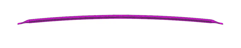
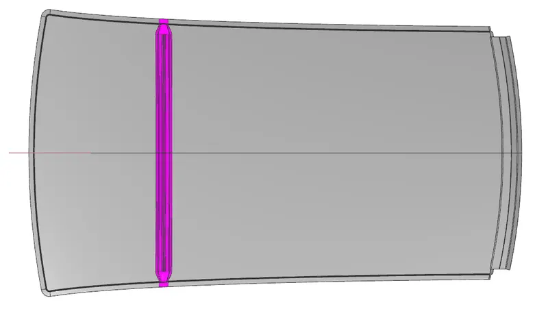
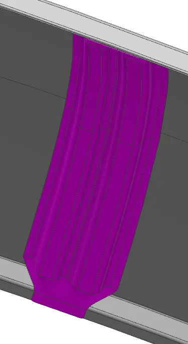
Master section has been taken from the designed surface
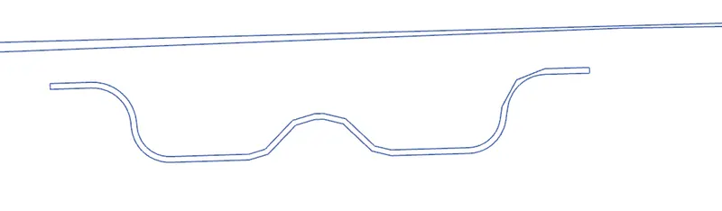
BOW ROOF REAR:
It is also same to the Front bow roof but the positioning bow roof only change. The bow roofs are given to the improve the torsional stiffness and load bearing capacity of the roof structure. When number of bow roofs are given by the roof dimension. Longer the roof area we have to give the more bow roof to the structure.But, remember we place bow roof in flatter region for enhance strength of the roof.
given master section for bow roof rear
bow roof have been designed with respect to the given master section.
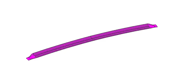
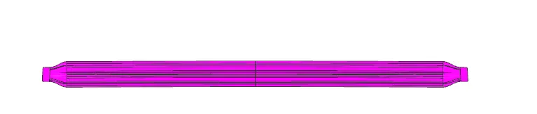
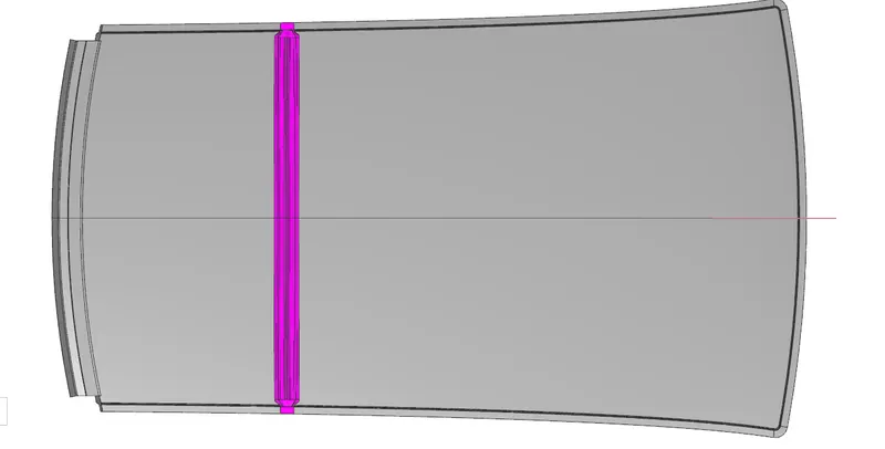
master section have been created from the designed surface.
HEAT DISTORTION
Heat distortion calculation on a car roof involves assessing the potential effects of heat on the roof material, particularly when exposed to high temperatures. The calculations primarily consider the coefficient of thermal expansion (CTE) and the material's melting or softening point.
-
Coefficient of Thermal Expansion (CTE): The CTE is a property that describes how a material expands or contracts with changes in temperature. It is measured in units of length per degree Celsius (or Fahrenheit). The CTE value indicates how much a material will expand or contract for each degree of temperature change. The CTE value is typically provided by the material manufacturer.
-
Melting or Softening Point: The melting or softening point is the temperature at which a material changes from a solid to a liquid state or becomes pliable and prone to distortion. Different materials have different melting or softening points, which are also provided by the material manufacturer.
To calculate heat distortion on a car roof, the following steps can be followed:
-
Determine the CTE of the roof material: Consult the material specifications or manufacturer's documentation to find the coefficient of thermal expansion (CTE) for the roof material.
-
Determine the temperature change: Identify the maximum temperature difference that the car roof is expected to experience. This could be estimated based on the climate conditions in your area or the expected temperature increase due to direct sunlight exposure.
-
Calculate the thermal expansion: Multiply the CTE of the material by the temperature change to obtain the thermal expansion. This value represents how much the material will expand or contract due to the temperature change.
-
Compare with material properties: Compare the calculated thermal expansion value with the material's limitations. Consider the melting or softening point of the material. If the calculated thermal expansion exceeds the material's capacity to withstand the expansion without deforming or reaching its softening point, it could lead to heat distortion on the car roof.
FORMULA FOR HEAT DISTORTION
W = [1.73 x 10^(-3) x L] + [1.85 x 10^(-8) x (R^2)/t] + [ 1.10x10^(-3) x l] - 2.68
Where,
L = Roof Length in X-Direction[mm](Roof dimension in 0-Y)
R = Roof curvature
R = 2(Rx*Ry)/(Rx+Ry)
Rx = X curvature
Ry = Y curvature
t = Roof plate thickness [mm]
l = Bow Roof Span [mm]
JUDGMENT CONDITION OK IF < 2.7
STEPS FOR CREATING THE HEAT DISSORTION OF THE DESIGNED ROOF
Activate the assembly and create a new sketch and draw the center line on the roof of the top view.
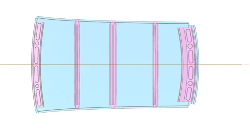
Then make ends of the all-roof rails visible by projecting the curve.
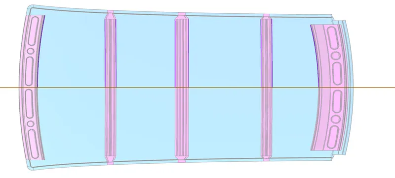
Then offset the center line above 300mm.
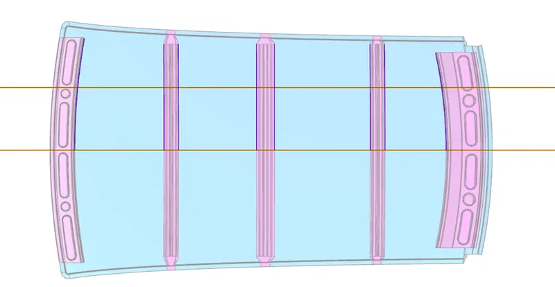
Then create a center line vertically inbetween the front roo rail and front bow roof rail.
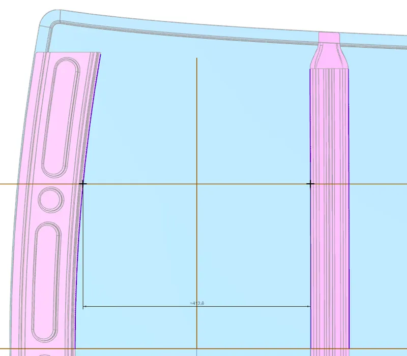
Create a line on these two lines on each side with 100 mm distance.
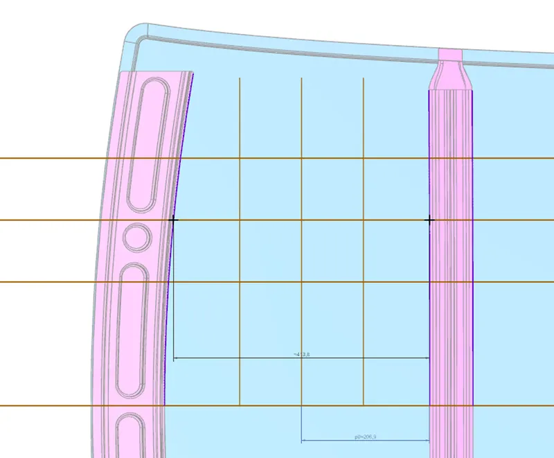
Like this create inbetween all the roof rails and make a intersection point.
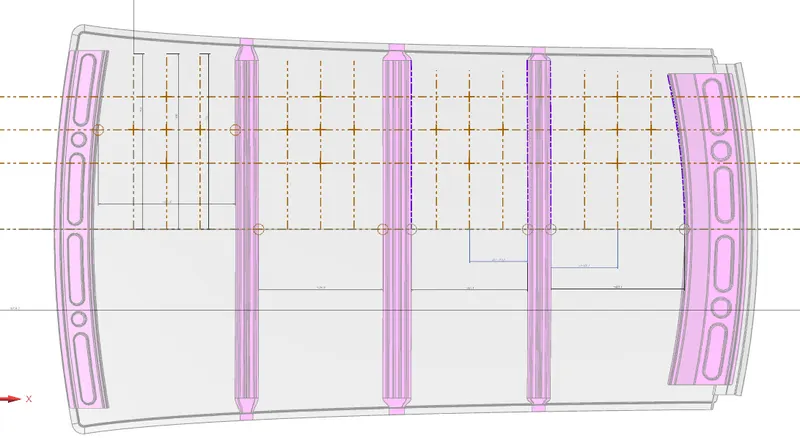
Then using the 3 point arc option create a arc and join that points.
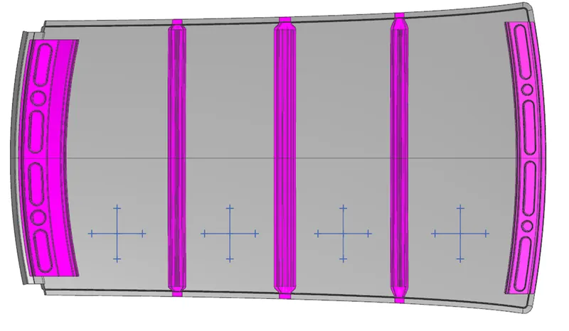
Measure the arc radius.Now the RX and RY was obtained.
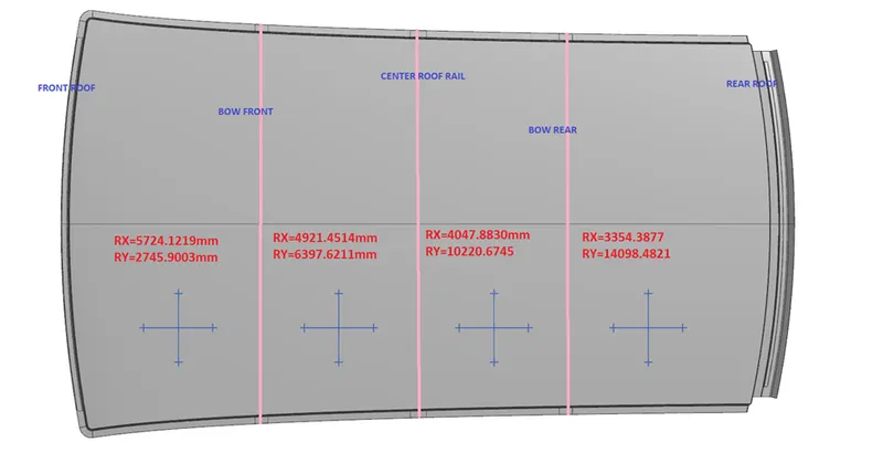
Now we want to find the overall length of the roof rail.
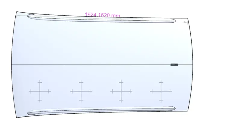
For finding the I value calculate the distance between the two sides of the each rails.
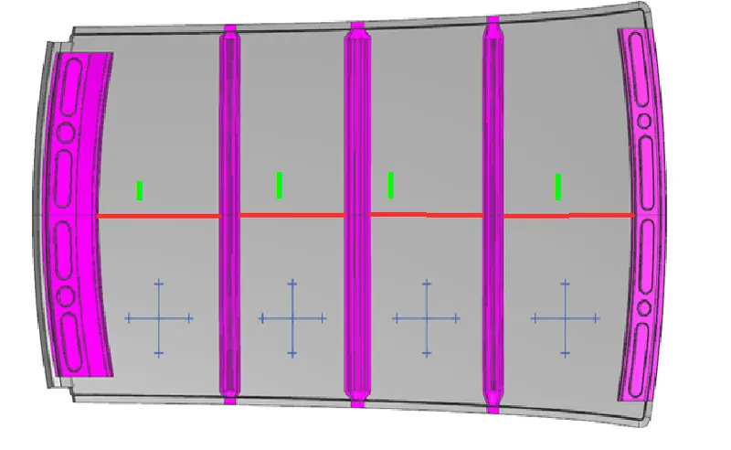
Now all the values have been obtained and we can start the calculation.

ALL VALUES ARE LESS THAN 2.7 SO IT IS PERFECT TO MANUFACTURE.
SNOW LOAD PREDICTION FORMULA
Qr = [Iy x t2] / [α x s x [(Rx + Ry)/2]2 x 10-8]
Where,
α = My x Lx2 x 10-12 , My = Y(Ly-Y)
t = Roof plate thickness [mm]
Ly = Distance between the front and rear roof Rails on the Vehicle along with 0Y[mm]
Length of Roof panel with the center point between Roof rail Front /Rear as the front and rear reference point.
Lx = Distance between the Left and Right end of the roof on the Roof BOW [mm]
The width of the roof panel is exposed on the surface.
Y = Distance front Front Roof Rail to Roof BOW[mm]
s = Distance for which Roof BOW bears divided load [mm]
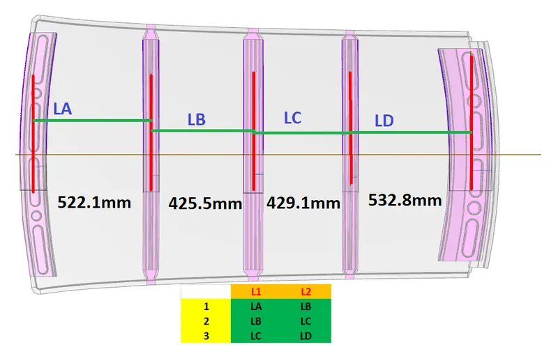
s = L1/2 + L2/2
Iy = Geometrical moment of inertia of Roof BOW (Y cross-section )[mm4]
Rx = Lateral direction curvature radius of roof panel Y cross-section on Roof BOW [mm]
Roof panel curvature Radius of the Length Lx in Front view
Ry = Longitudinal Direction curvature radius of the Roof panel X cross-section on Roof BOW [mm]
Roof panel X curvature radius of length s in Side view
First we want to identify the IY moment of inertia value for that section modulus has been taken for all roof rails.
FRONT BOW ROOF(Moment of inertia)
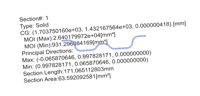
Moment of inertia,( MAX) I max =2.6401×10⁴( mm4)
Moment of inertia,( MIN) I min =931.2960( mm4)
CENTER ROOF(Moment of inertia)
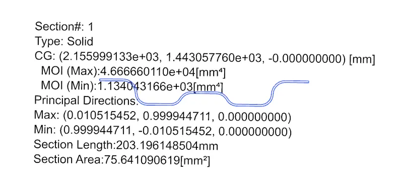
Moment of inertia,( MAX) I max =4.666×10⁴( mm4)
Moment of inertia,( MIN) I min =1.13404x10³( mm4)
REAR BOW ROOF(Moment of inertia)
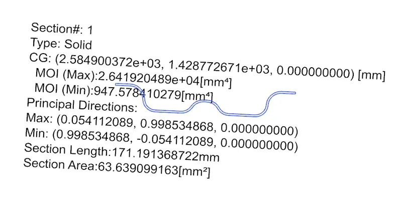
Moment of inertia,( MAX) I max =2.6419×10⁴( mm4)
Moment of inertia,( MIN) I min =947.578( mm4)
VALUE OF LY=2035.5384
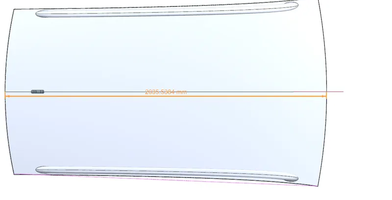
VALUE OF LX ARE SHOW IN THE IMAGE
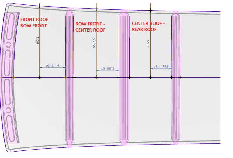
For finding the value of L1 and L2 we want to measure the distance between center of the each roof rails.
Below image shows that how to find the values of L1 and L2.
Next we want to find the RX and RY values.
For finding RX and RY value create a center line in the horizontal axis and offset the line on the both sides with 100mm each.
And create a center line between two rails and offset that center line on both sides with 10mm each.
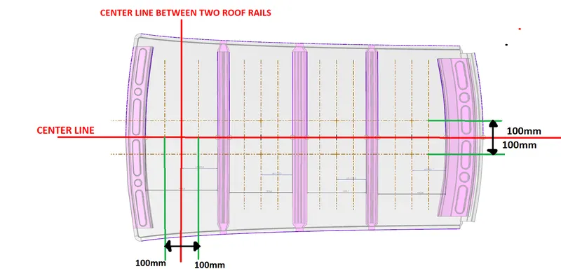
After creating that point using the three point arc option joint those vertical points and horizontal points and measure the radius value.
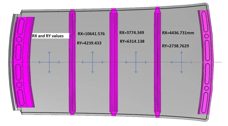
Next we want to take the values of Y.For that below image shows how to measure the distance for Y value.
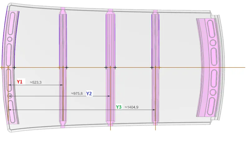

If roof structure pass to the snow load condition. They, must have Qr values from above 3.1.
Qr > 3.1
So, we done the curvature study on the roof. For the heat diisortion condition my roof design has passed and it is ok to manufature.But snow load condition my roof design have failed and want to modify the position of the roof and want to add the emboss to the structure.By this we can incerese the srength of the roof assembly
DRAFT ANALYSIS:
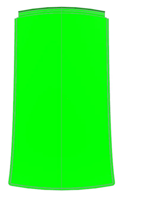
The Draft Analysis command enables you to detect if the part you drafted will be easily removed. This type of analysis is performed based on color ranges identifying zones on the analyzed element where the deviation from the draft direction at any point, corresponds to specified values.
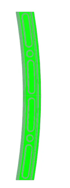
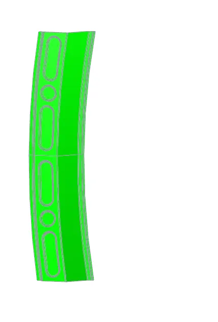
Minimum draft angle is 7 degree is considered for analysis. Green colour show positive draft angle of the part more than 7 degree.
ROOF RAIL
roof rail has passed the draft analysis
FRONT ROOF RAIL
REAR ROOF RAIL
CENTER ROOF RAIL

BOW ROOF RAIL 1

BOW ROOF RAIL 2

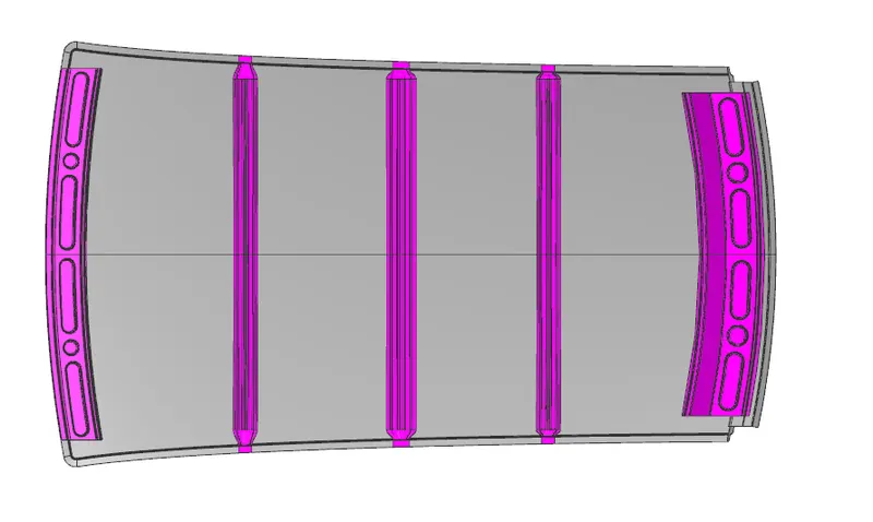
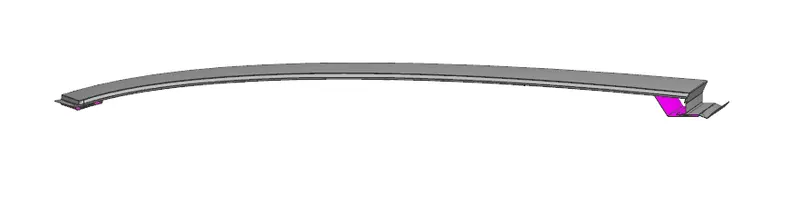
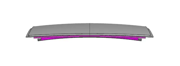
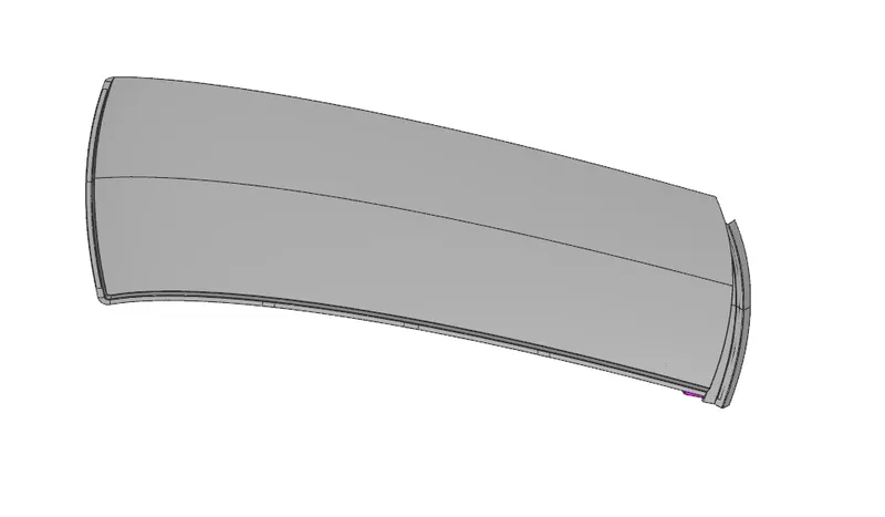
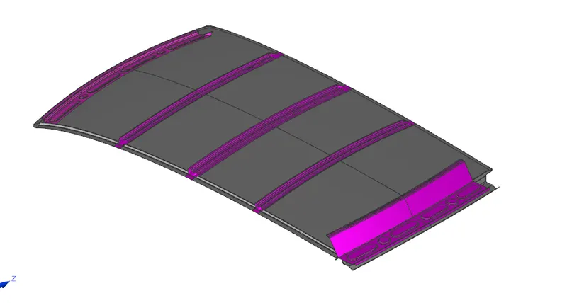
ROOF VIEWS
CONCLUSION
Hence the roof , front roof rail, bow roof rails , central roof rail and the rear roof rail is designed by following the master sections and the moment of inertia and draft analysis are carried out to check feasibility manufacturing.