Roof Design
Roof Design:
The roof has been designed using the master section provided. This design incorporates 2 bow roofs with a center reinforcement roof. The front roof panel and the rear roof panel are also designed following the master section.
1. Roof outer panel
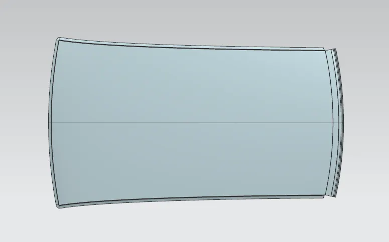

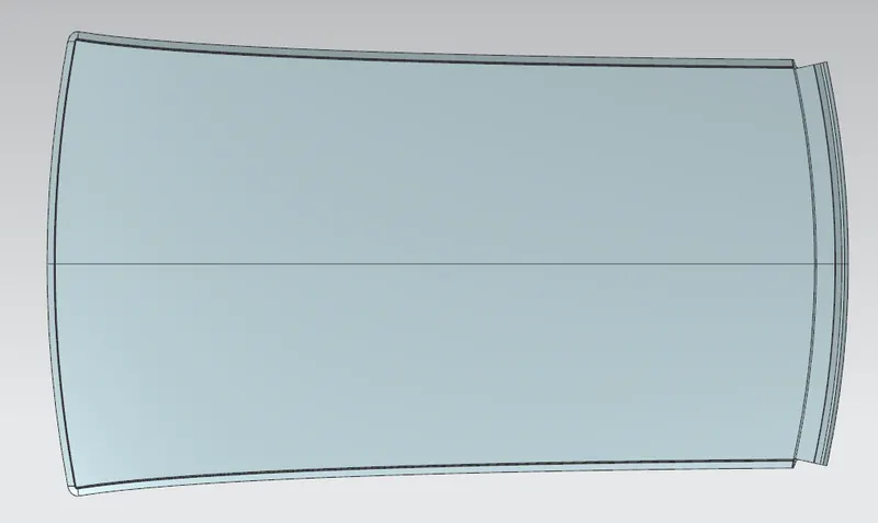
2. Front roof panel
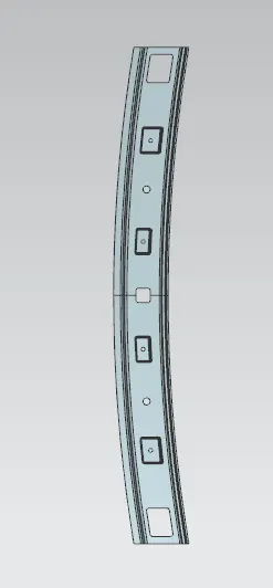
3. Rear roof panel
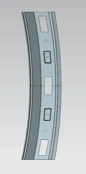
4. Bow roof 1
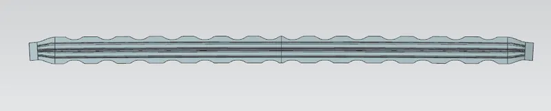
5. Bow roof 2

6. Center roof with reinforcement

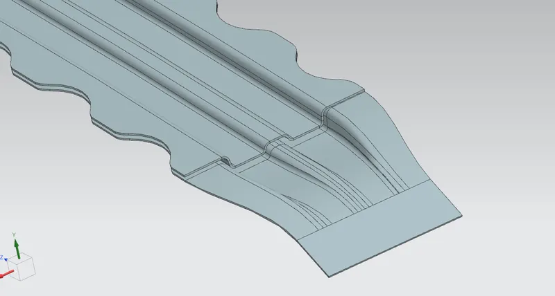
Roof Assembly:
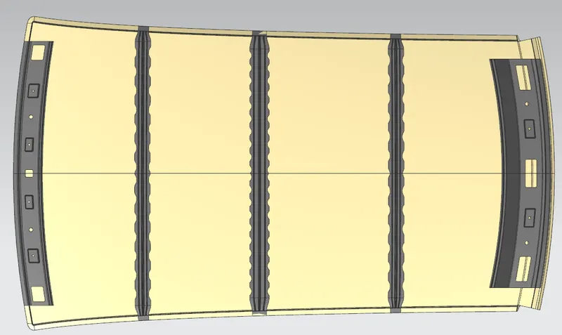
Bow roof calculations:
Heat distortion:
W = [1.73 x 10^(-3) x L] + [1.85 x 10^(-8) x (R^2)/t] + [ 1.10x10^(-3) x l] - 2.68
Where,
L = Roof Length in X-Direction[mm](Roof dimension in 0-Y)
R = Roof curvature
R = 2(Rx*Ry)/(Rx+Ry)
Rx = X curvature
Ry = Y curvature
t = Roof plate thickness [mm]
l = Bow Roof Span [mm]
To find Rx and Ry,
- Create a sketch and draw a horizontal line at the center.
- Offset this line below 300mm. This line is called as -3Y line.
- Offset the -3Y line 100 mm above and below and convert all these lines into reference lines.
- Draw the vertical lines at the middle of each reinforcement and offset it to 100 mm on both sides.
- An intersection point is created where the lines are met.
- Project these points to the outer roof panel.
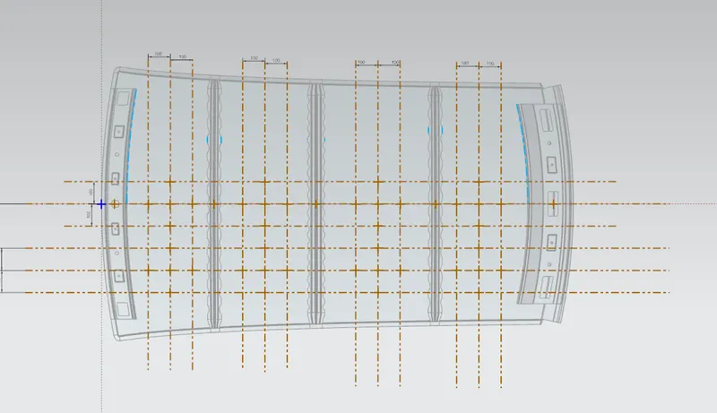
Points projection on the outer panel:
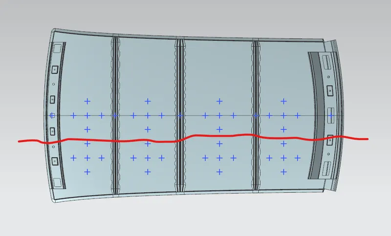
Consider the points below the red line for heat distortion.
Rx radius:
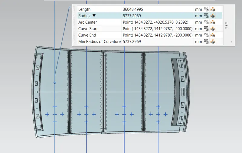
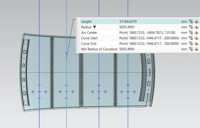
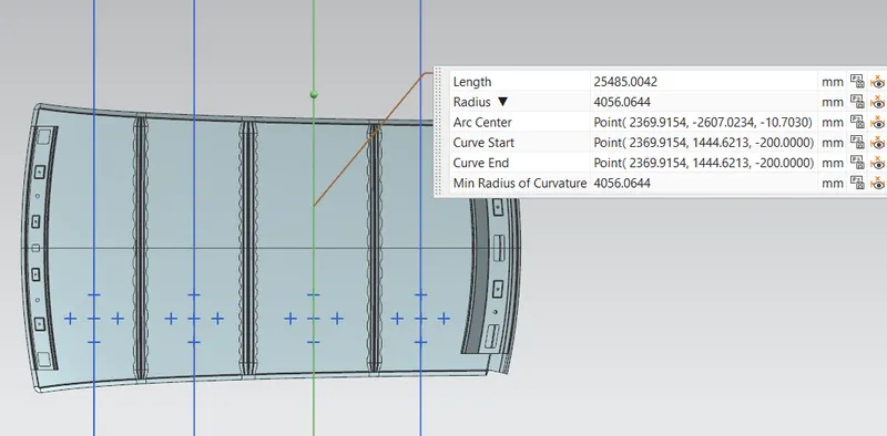
To find the Rx radius, draw an arc using the three-point arc and measure it.
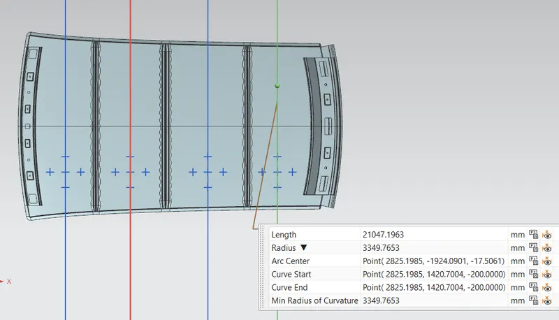
Ry radius:
Draw an arc using the three points in the 1st segment and measure it.
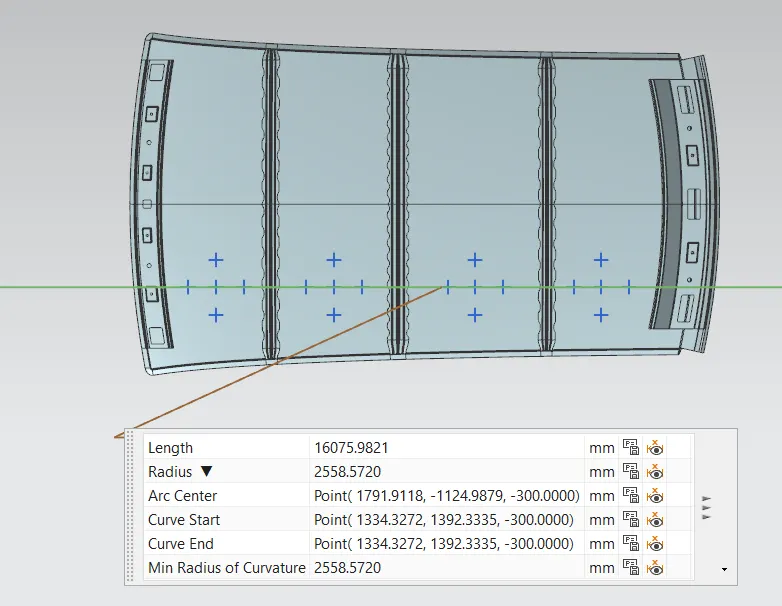
2nd segment
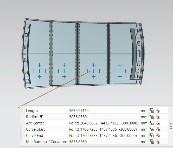
3rd
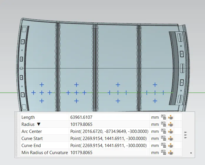
4th
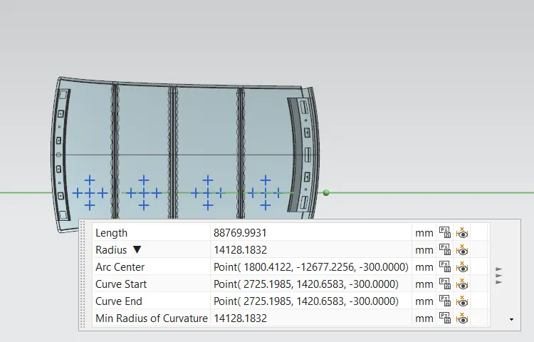
Tabulate the results

Here, the W values are less than 2.7. Therefore, this roof design satisfies the heat distortion condition.
Snow load:
Similar to heat distortion, the required values are measured and tabulated.
Moment of inertia of bow roof 1, 2, and centre roof:
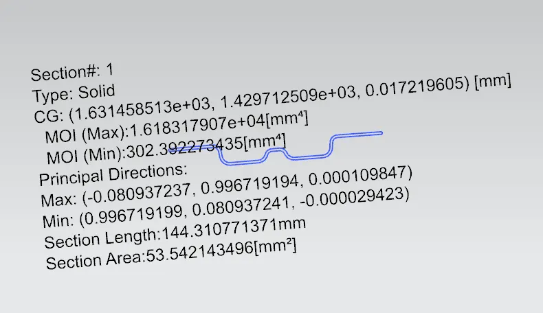
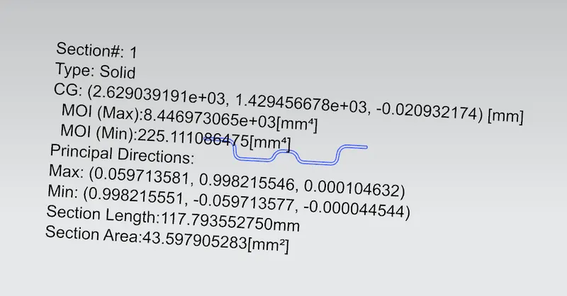
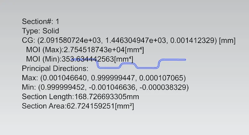
Min MOI value is taken for calculations.
Tabulation:

Here, we can see that the s values are greater than 380, and also the Qr values are less than 3.1. Therefore, this roof design has failed the snow load condition.
As a countermeasure, we can add another bow roof for reinforcement which brings down the L1 and L2 values so that it solves the s value error. Consequently, Qr values will also increase.
Draft Analysis:
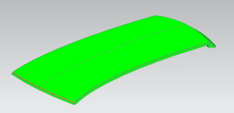
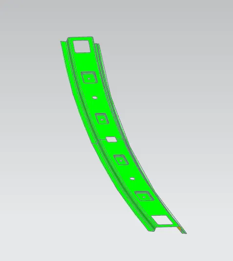
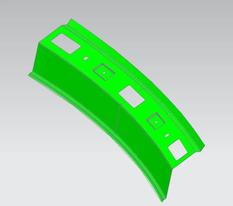
The limit angle is set at 7 deg.
1. Roof Outer panel:
2. Front roof panel:
3. Rear roof panel:
4. Bow roof 1

5. Bow roof 2

6. Centre roof

Conclusion:
The roof was designed following the master section and the rules and the calculation for heat distortion and snow load conditions was performed. Countermeasure was provided for the snow load condition failure. Finally, draft analysis was performed on the design.